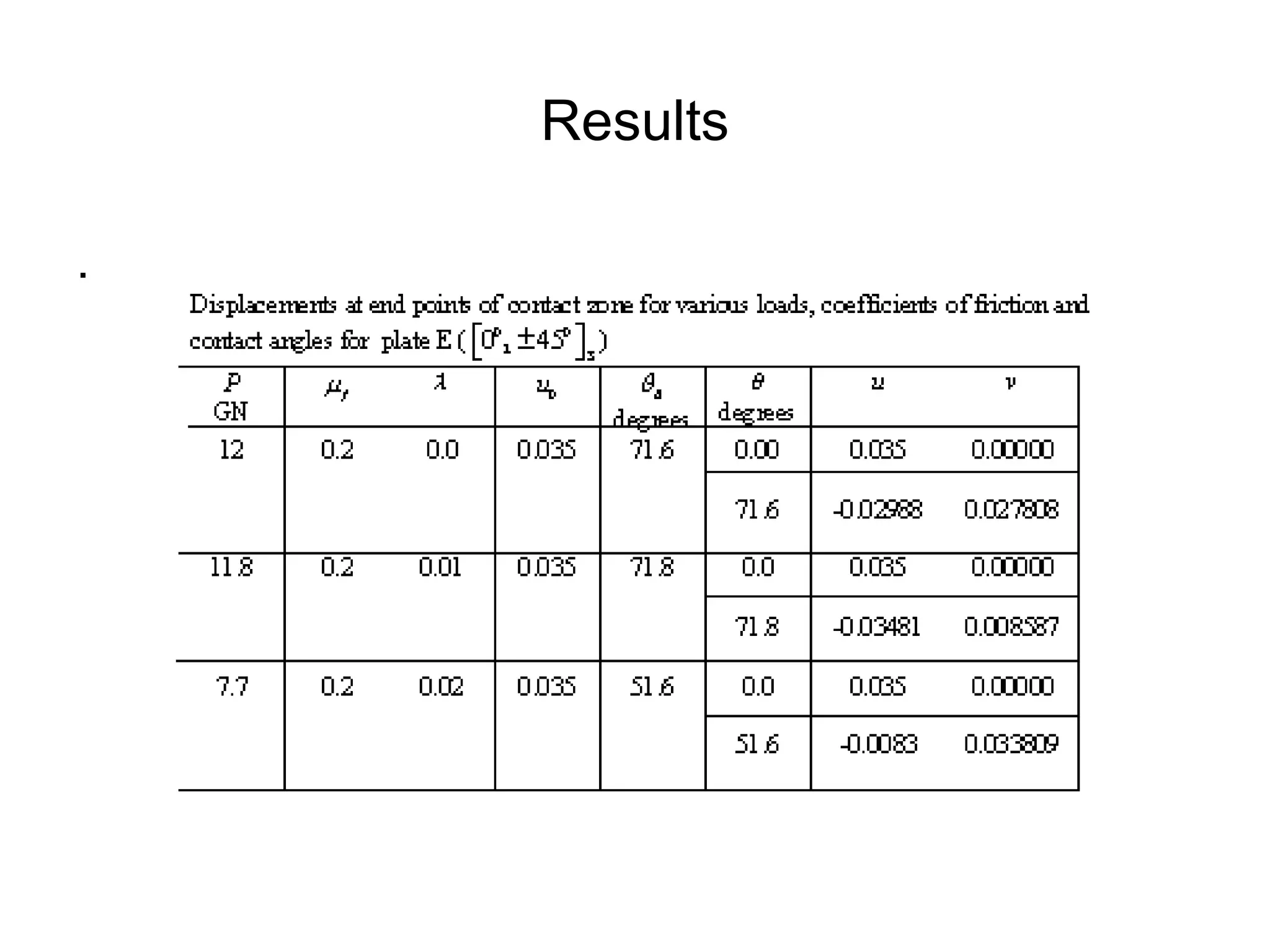
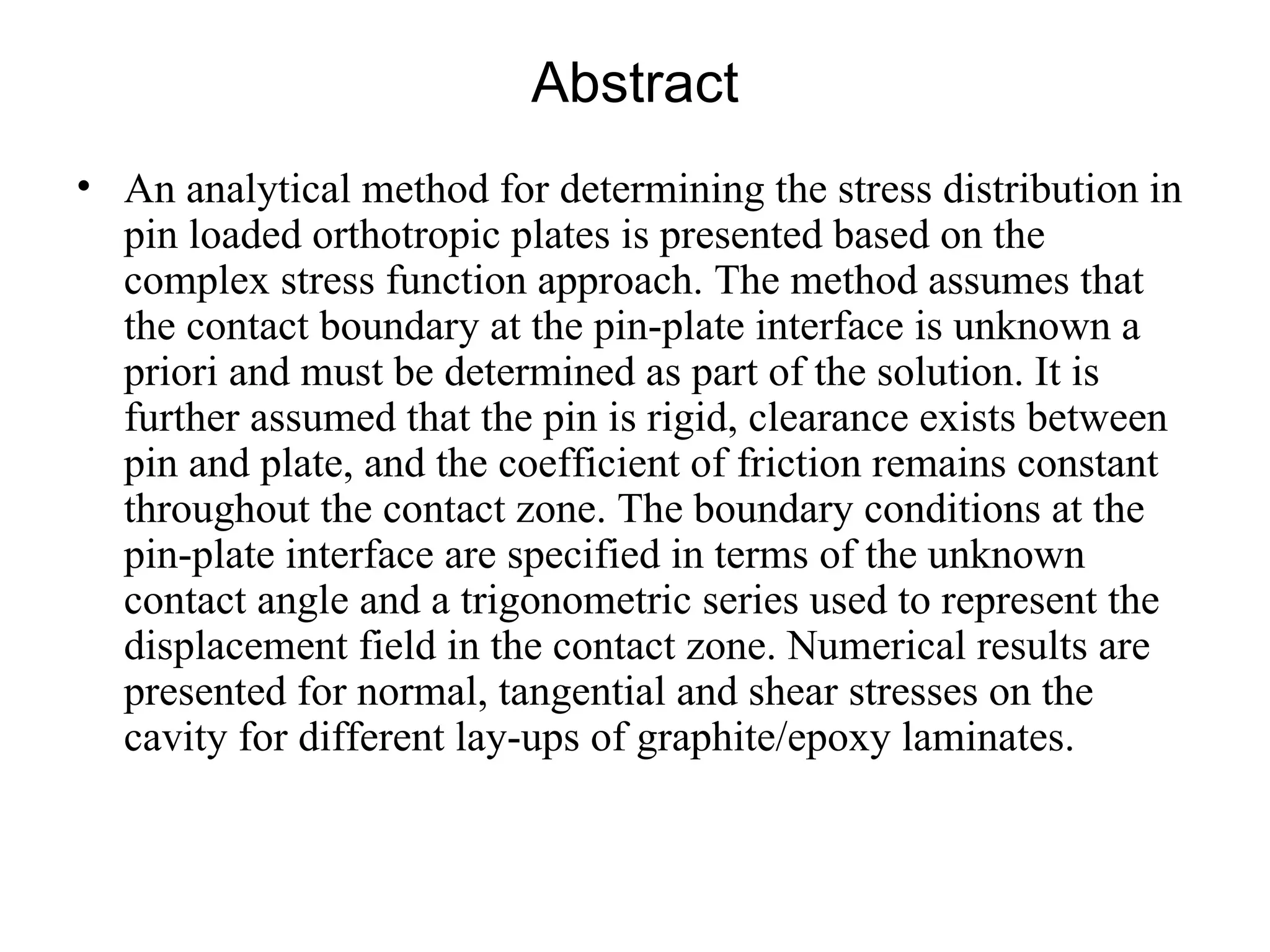
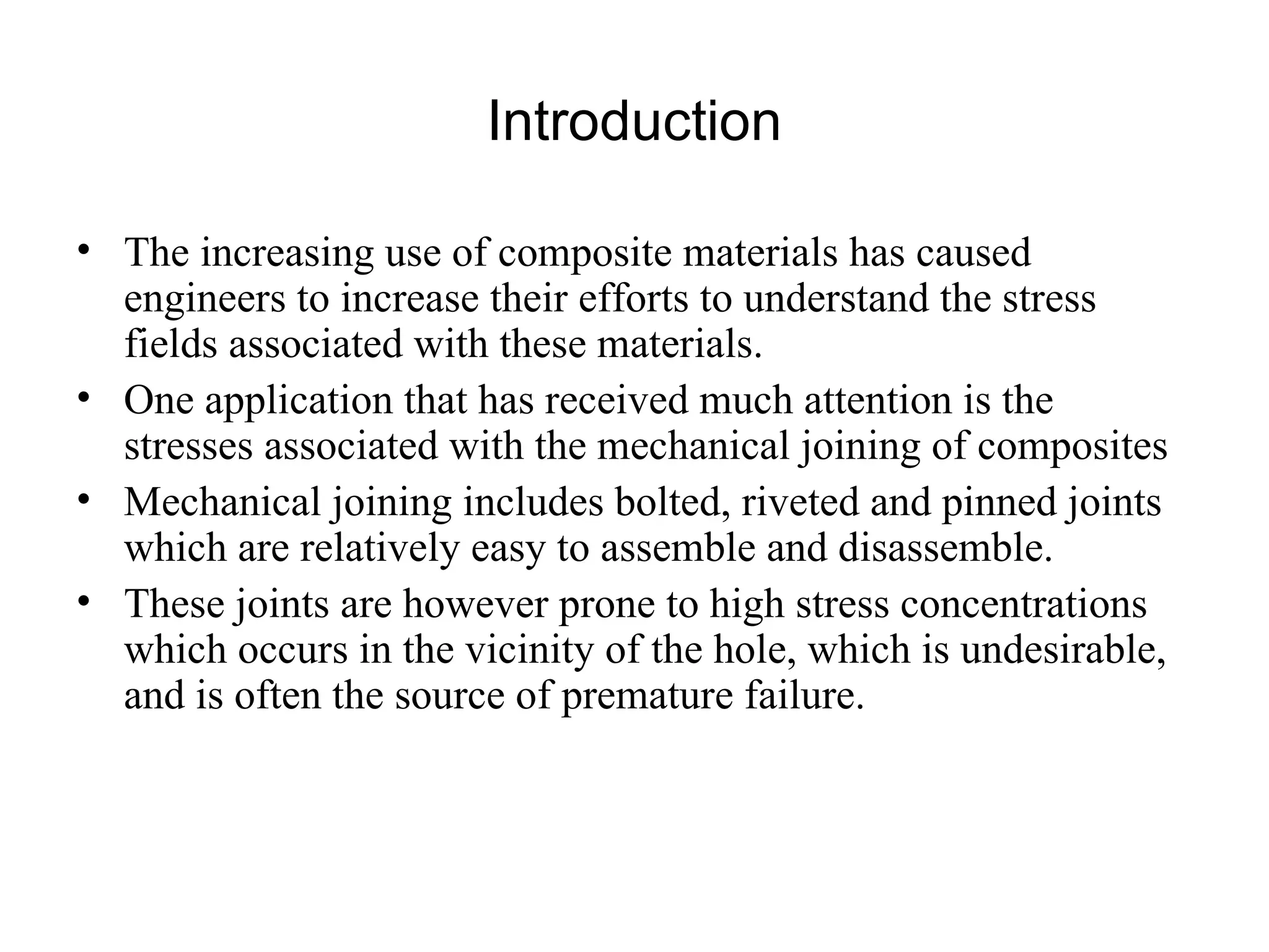
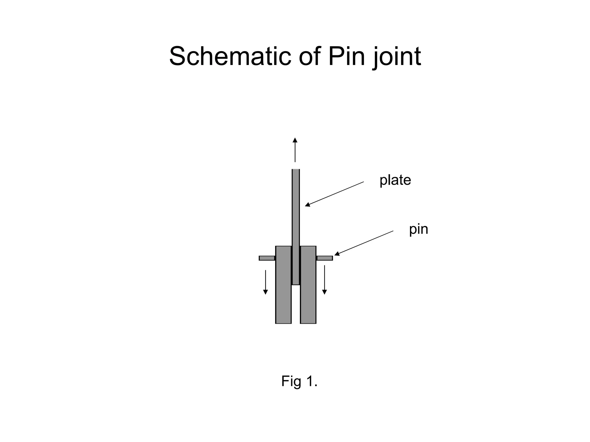
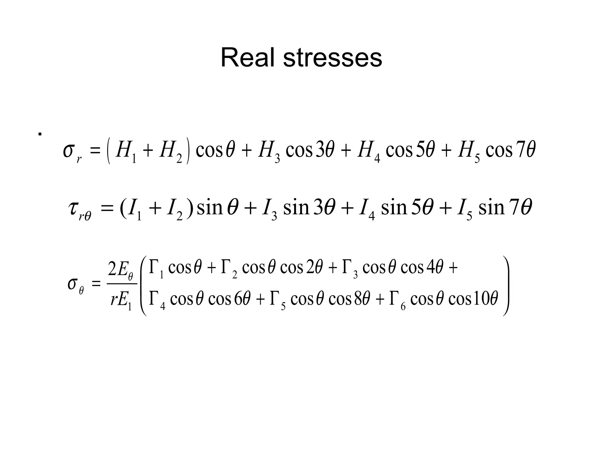
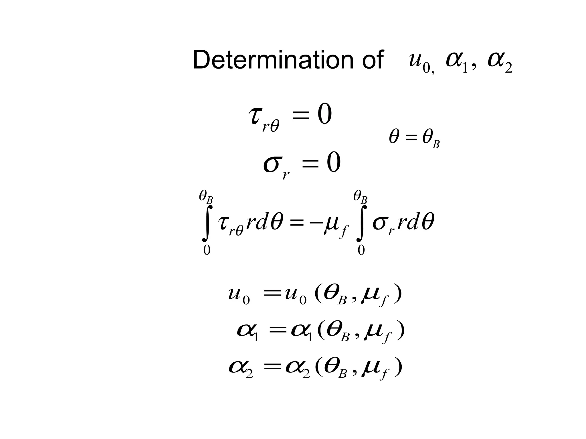
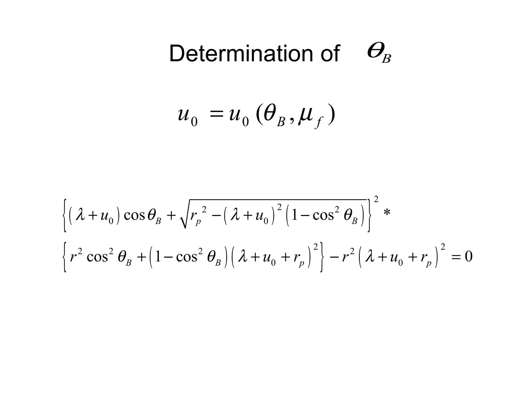
The document presents an analytical method for determining stress distributions in pin-loaded orthotropic plates. The method assumes a rigid pin, clearance between the pin and plate, and a constant coefficient of friction. Numerical results are shown for normal, tangential and shear stresses on the cavity for different composite layups. The method can predict stresses for varying clearances and a perfectly fitting pin. Experimental validation and improvements to contact modeling are recommended.


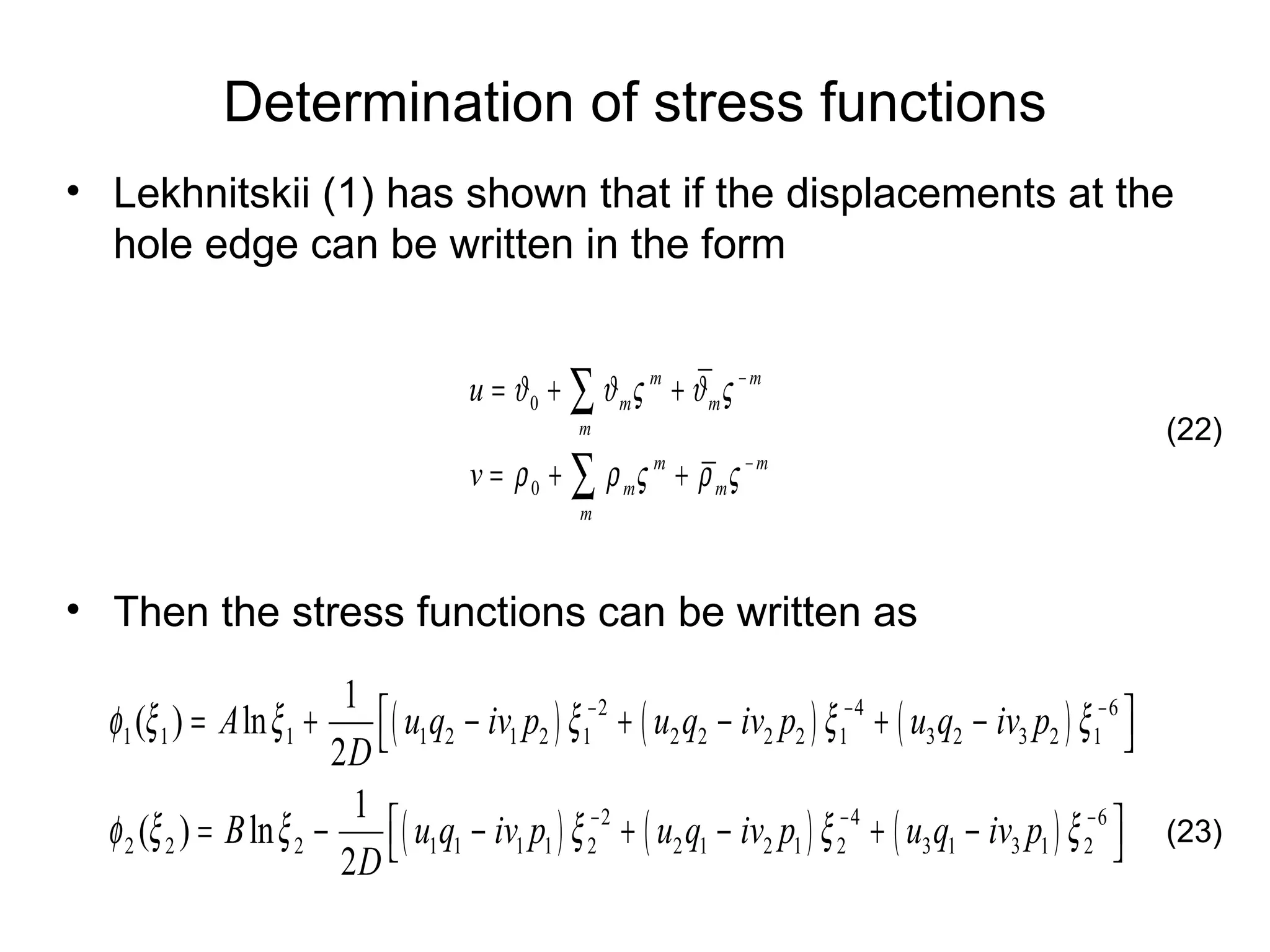
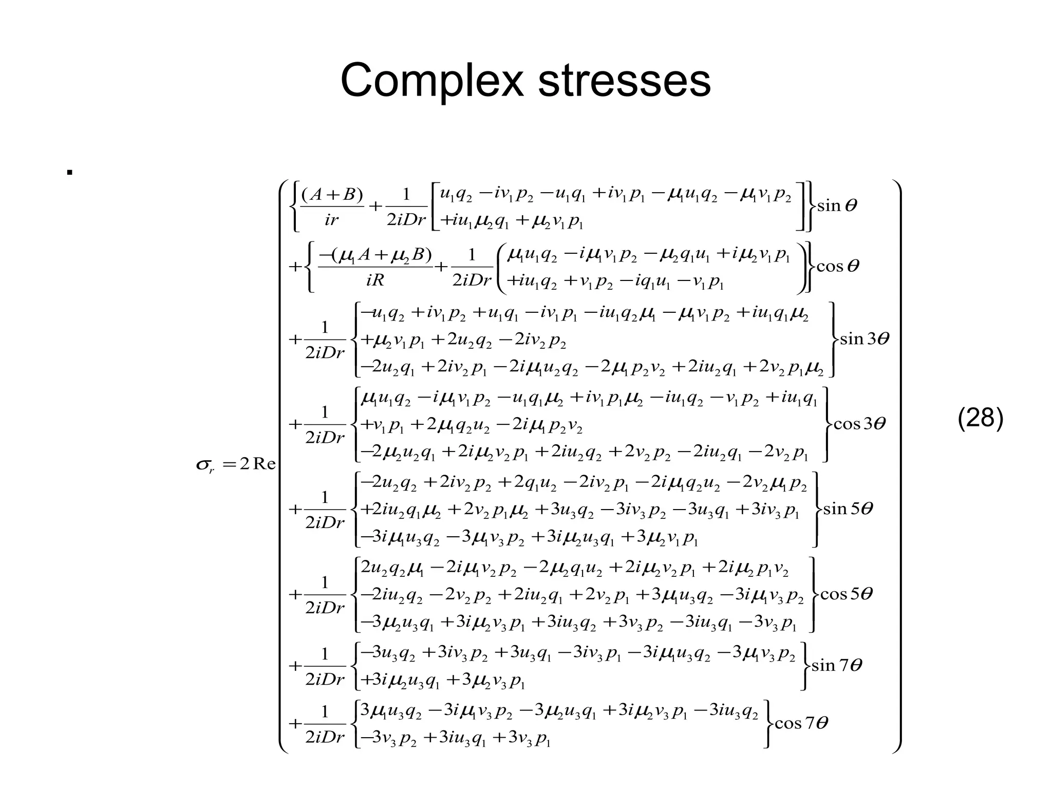
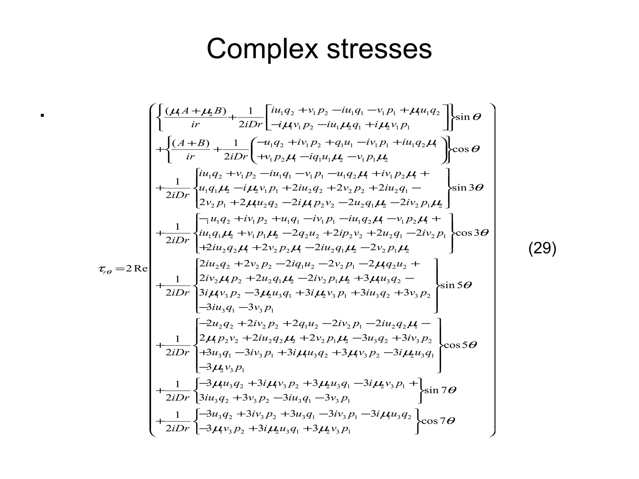
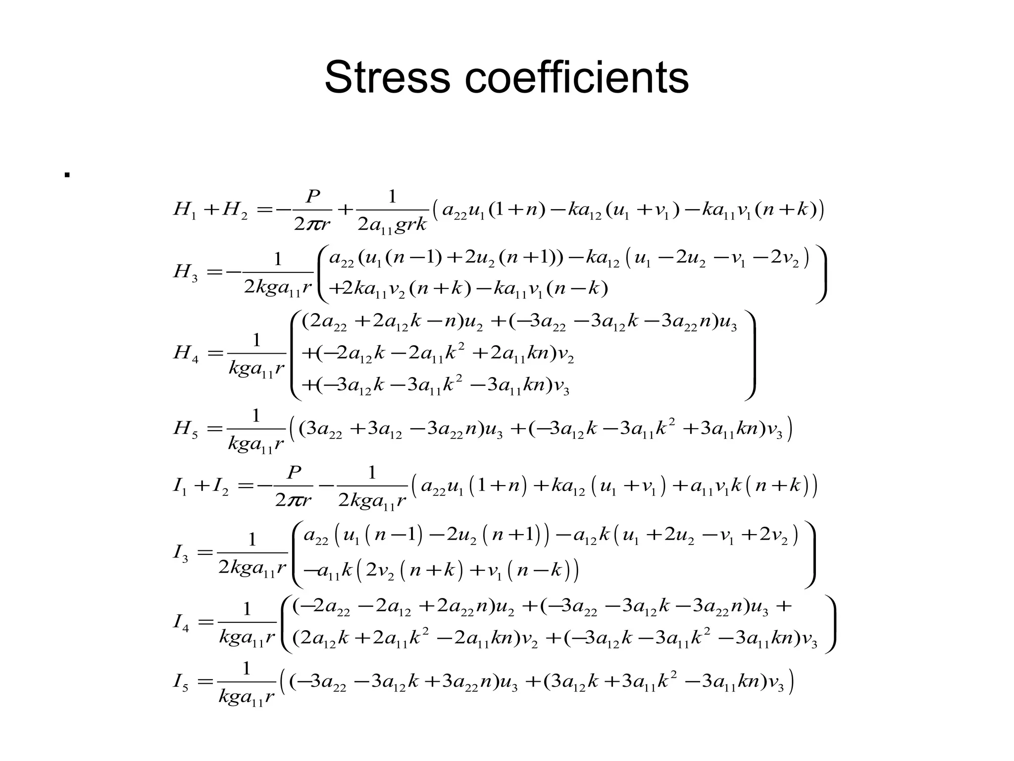
![Stress coefficients . All constants not shown can be obtained from [2] Appendix A](https://image.slidesharecdn.com/utechpresentation-13067134447376-phpapp02-110529191737-phpapp02/75/Utech-Presentation-29-2048.jpg)
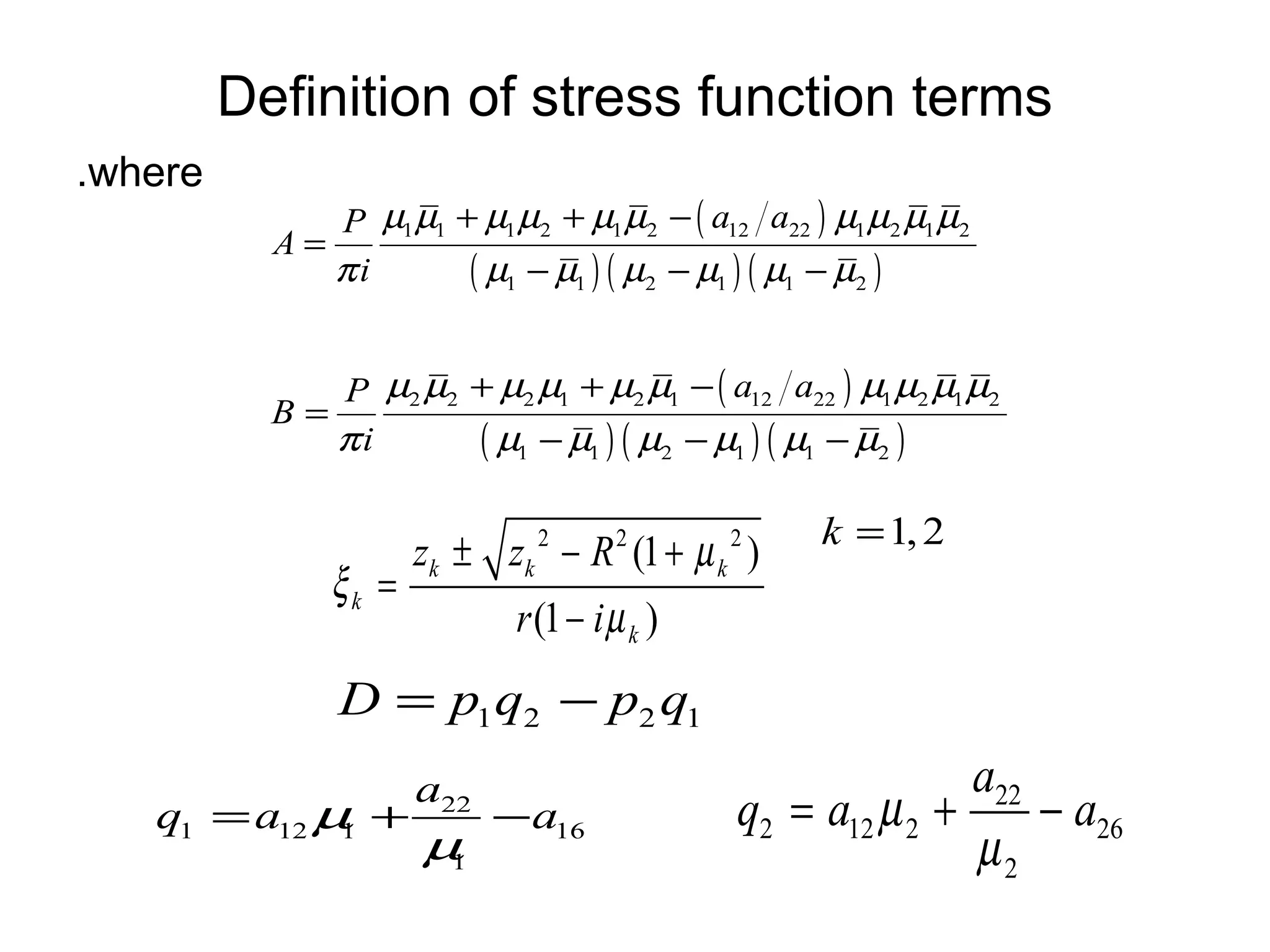
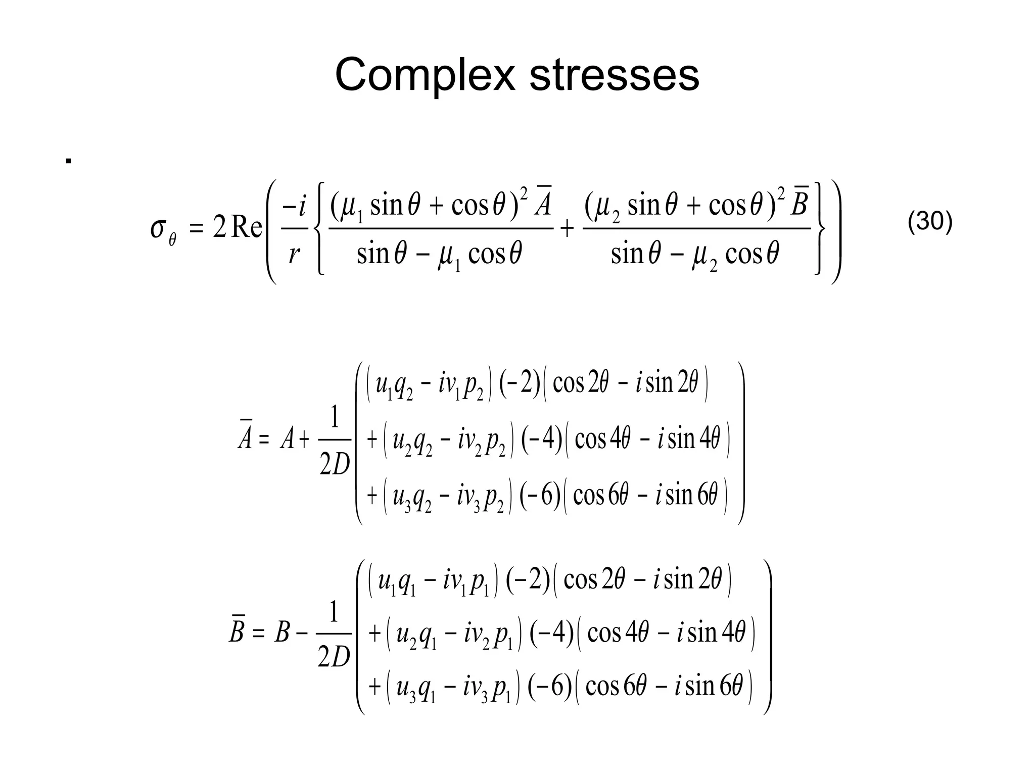
![Stress coefficients . All constants not shown can be obtained from [2] Appendix A](https://image.slidesharecdn.com/utechpresentation-13067134447376-phpapp02-110529191737-phpapp02/75/Utech-Presentation-30-2048.jpg)
![Results . Radial stress for plate E ( [0 2 / ±45] s )](https://image.slidesharecdn.com/utechpresentation-13067134447376-phpapp02-110529191737-phpapp02/75/Utech-Presentation-39-2048.jpg)
![Results . Shear stress for plate E ( [02/±45]s )](https://image.slidesharecdn.com/utechpresentation-13067134447376-phpapp02-110529191737-phpapp02/75/Utech-Presentation-40-2048.jpg)
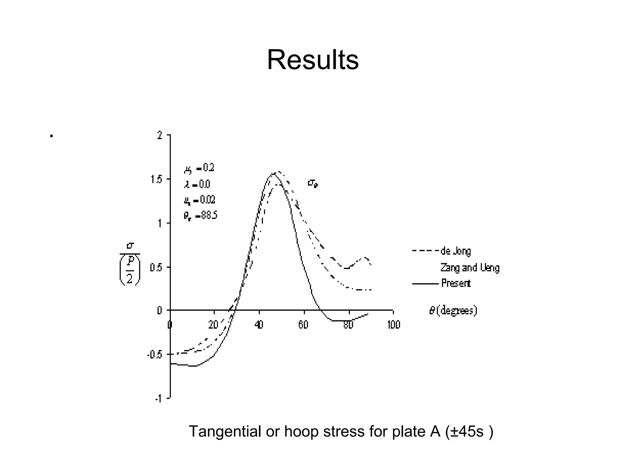
![Results . Tangential or hoop stress for plate E ( [02/±45]s )](https://image.slidesharecdn.com/utechpresentation-13067134447376-phpapp02-110529191737-phpapp02/75/Utech-Presentation-41-2048.jpg)