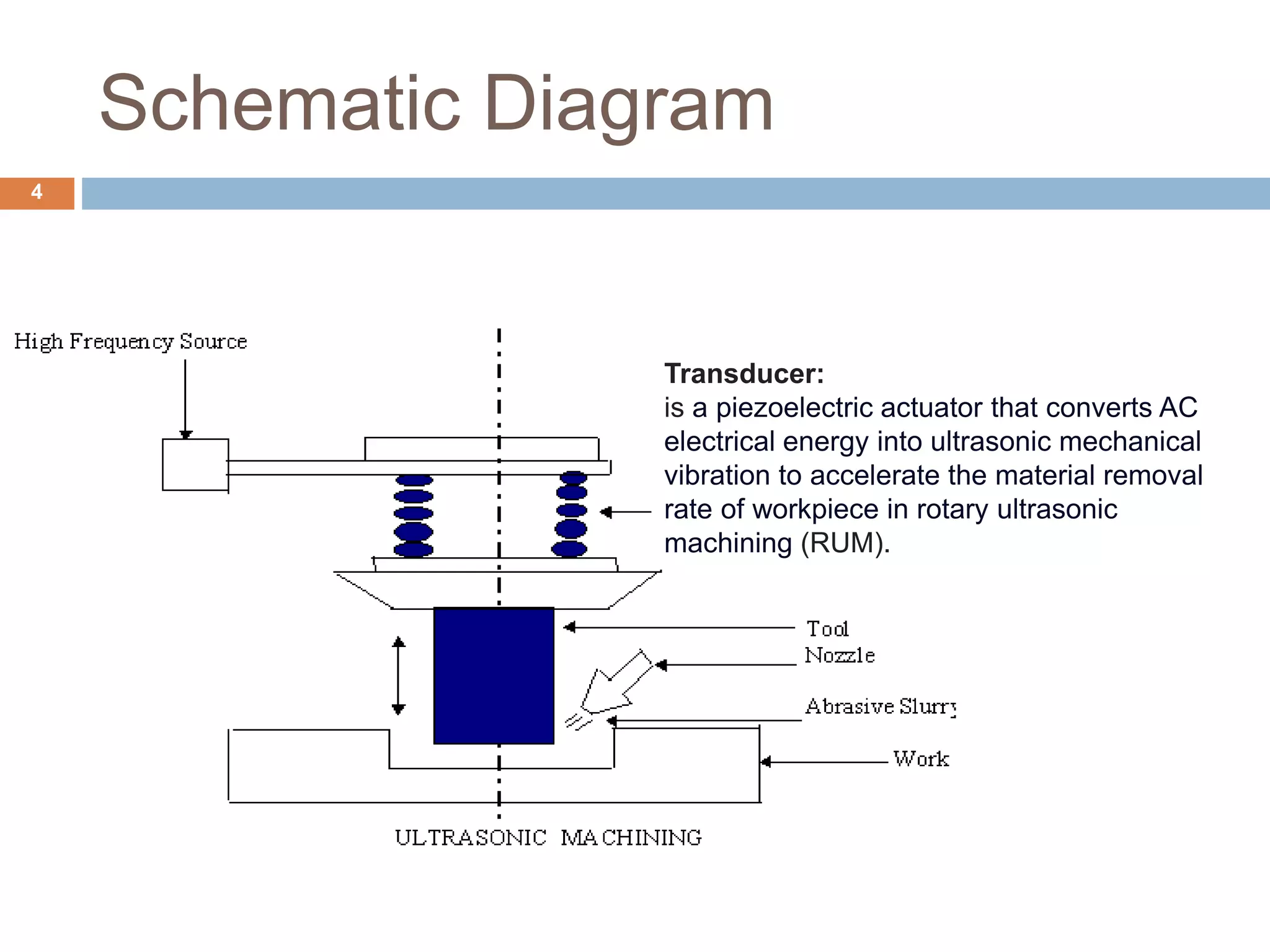
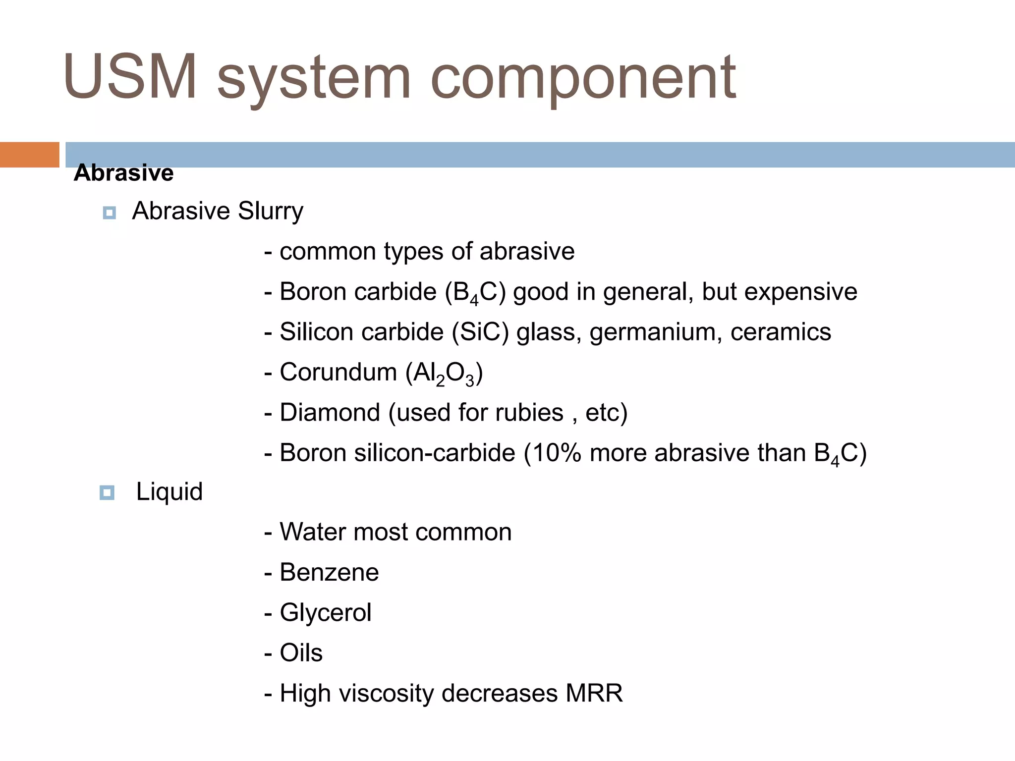
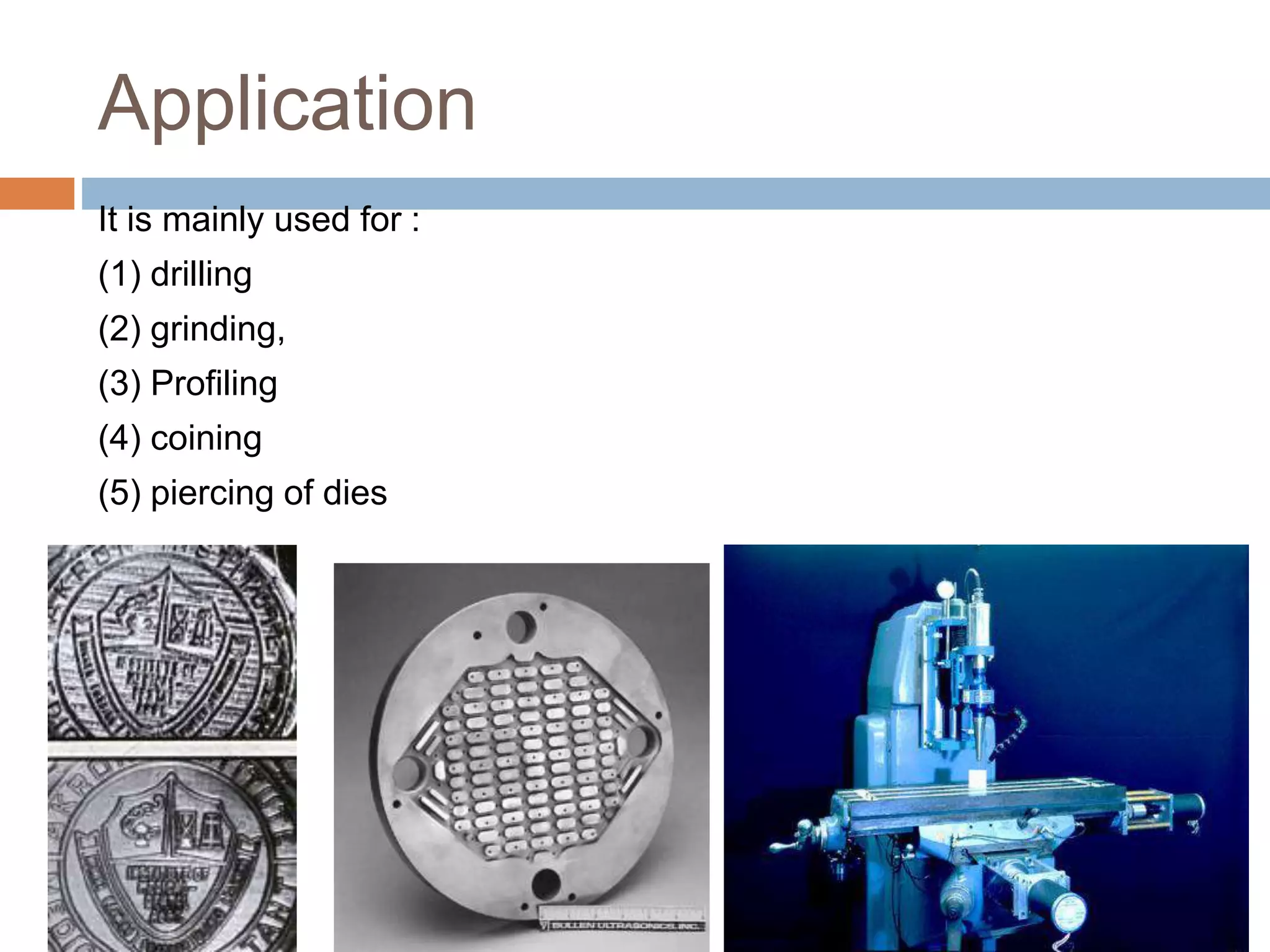
Content
1. Introduction
2. Schematic diagram
3. Principle & Working
4. Mechanism
5. USM system & subsystem
6. Process parameter & effect
7. Application
8. Advantages & disadvantages
Objective:
To learn other types of machining processes other
than traditional machining.
Ultrasonic Machining
 It is a non traditional mechanical material removal process, used to
erode material in the form of fine holes and cavities in hard or brittle
workpiece such as graphite, glass, carbide, and ceramics.
 It uses formed tools, vibrations of high frequency and a suitable
abrasive slurry mix.
 Frequency > 20,000 Hz.
Schematic Diagram
4
Transducer:
is a piezoelectric actuator that converts AC
electrical energy into ultrasonic mechanical
vibration to accelerate the material removal
rate of workpiece in rotary ultrasonic
machining (RUM).
Working Principle
 The process is performed
by a cutting tool, which
oscillates at high frequency,
typically 20-40 kHz, in
abrasive slurry.
 The high-speed
reciprocations of the tool
drive the abrasive grains
across a small gap against
the workpiece .
 The impact of the abrasive
is the energy principally
responsible for material
removal in the form of small
wear particles that are
carried away by the
abrasive slurry.
 The shape of the tool
Mechanism for material removal
 the abrasive particles are struck by the
downstroke of the vibration tool.
 Collapse of the cavitation bubbles in the
abrasive suspension results in very high local
pressures.
 Microcracks are generated at the interface of
the workpiece – brittle fracture.
 The brittle fracture lead to
chipping of particles from the
workpiece.
USM system components
4/19/2023
1. Power supply
2. Transducer
3. Tool holder
4. Tool
5. Abrasive slurry
USM system component
Abrasive
 Abrasive Slurry
- common types of abrasive
- Boron carbide (B4C) good in general, but expensive
- Silicon carbide (SiC) glass, germanium, ceramics
- Corundum (Al2O3)
- Diamond (used for rubies , etc)
- Boron silicon-carbide (10% more abrasive than B4C)
 Liquid
- Water most common
- Benzene
- Glycerol
- Oils
- High viscosity decreases MRR
USM system component
Tool
 Tool material should be tough and ductile. Low carbon steels and
stainless steels give good performance.
 Tools are usually 25 mm long ; its size is equal to the hole size minus
twice the size of abrasives.
 Mass of tool should be minimum possible so that it does not absorb
the ultrasonic energy.
 It is important to realize that finishing or polishing operations on the
tools are sometimes necessary because their surface finish will be
reproduced in the workpiece.
 Tool and toolholder are often attached by silver brazing.
Process Parameters
1. Amplitude of vibration (a) - 15- 50 um.
2. Frequency of vibration (f)-19-25kHz
3. Feed force (F)
4. Feed pressure (p)
5. Abrasive size-15-150um
6. Contact area of the tool – A
7. Volume concentration of abrasive in slurry -
C
Process Parameters
4/19/2023
Mohit Ostwal, Asst. Prof., JIET-coed, Jodhpur
Application
It is mainly used for :
(1) drilling
(2) grinding,
(3) Profiling
(4) coining
(5) piercing of dies
Advantages
 Machining any materials regardless of their conductivity
 USM apply to machining semi-conductor such as
silicon, germanium etc.
 USM does not produce electric, thermal, chemical
abnormal surface.
 Can drill circular or non-circular holes in very hard
materials
 Less stress because of its non-thermal characteristics
Disadvantages
 USM has low material removal rate. (3-15mm3/min)
 Tool wears fast in USM.
 Machining area and depth is restraint in USM.
Thanks

Ultrasonic Machining.pptx

  • 2.
    Content 1. Introduction 2. Schematicdiagram 3. Principle & Working 4. Mechanism 5. USM system & subsystem 6. Process parameter & effect 7. Application 8. Advantages & disadvantages Objective: To learn other types of machining processes other than traditional machining.
  • 3.
    Ultrasonic Machining  Itis a non traditional mechanical material removal process, used to erode material in the form of fine holes and cavities in hard or brittle workpiece such as graphite, glass, carbide, and ceramics.  It uses formed tools, vibrations of high frequency and a suitable abrasive slurry mix.  Frequency > 20,000 Hz.
  • 4.
    Schematic Diagram 4 Transducer: is apiezoelectric actuator that converts AC electrical energy into ultrasonic mechanical vibration to accelerate the material removal rate of workpiece in rotary ultrasonic machining (RUM).
  • 5.
    Working Principle  Theprocess is performed by a cutting tool, which oscillates at high frequency, typically 20-40 kHz, in abrasive slurry.  The high-speed reciprocations of the tool drive the abrasive grains across a small gap against the workpiece .  The impact of the abrasive is the energy principally responsible for material removal in the form of small wear particles that are carried away by the abrasive slurry.  The shape of the tool
  • 6.
    Mechanism for materialremoval  the abrasive particles are struck by the downstroke of the vibration tool.  Collapse of the cavitation bubbles in the abrasive suspension results in very high local pressures.  Microcracks are generated at the interface of the workpiece – brittle fracture.  The brittle fracture lead to chipping of particles from the workpiece.
  • 7.
    USM system components 4/19/2023 1.Power supply 2. Transducer 3. Tool holder 4. Tool 5. Abrasive slurry
  • 8.
    USM system component Abrasive Abrasive Slurry - common types of abrasive - Boron carbide (B4C) good in general, but expensive - Silicon carbide (SiC) glass, germanium, ceramics - Corundum (Al2O3) - Diamond (used for rubies , etc) - Boron silicon-carbide (10% more abrasive than B4C)  Liquid - Water most common - Benzene - Glycerol - Oils - High viscosity decreases MRR
  • 9.
    USM system component Tool Tool material should be tough and ductile. Low carbon steels and stainless steels give good performance.  Tools are usually 25 mm long ; its size is equal to the hole size minus twice the size of abrasives.  Mass of tool should be minimum possible so that it does not absorb the ultrasonic energy.  It is important to realize that finishing or polishing operations on the tools are sometimes necessary because their surface finish will be reproduced in the workpiece.  Tool and toolholder are often attached by silver brazing.
  • 10.
    Process Parameters 1. Amplitudeof vibration (a) - 15- 50 um. 2. Frequency of vibration (f)-19-25kHz 3. Feed force (F) 4. Feed pressure (p) 5. Abrasive size-15-150um 6. Contact area of the tool – A 7. Volume concentration of abrasive in slurry - C
  • 11.
    Process Parameters 4/19/2023 Mohit Ostwal,Asst. Prof., JIET-coed, Jodhpur
  • 12.
    Application It is mainlyused for : (1) drilling (2) grinding, (3) Profiling (4) coining (5) piercing of dies
  • 13.
    Advantages  Machining anymaterials regardless of their conductivity  USM apply to machining semi-conductor such as silicon, germanium etc.  USM does not produce electric, thermal, chemical abnormal surface.  Can drill circular or non-circular holes in very hard materials  Less stress because of its non-thermal characteristics
  • 14.
    Disadvantages  USM haslow material removal rate. (3-15mm3/min)  Tool wears fast in USM.  Machining area and depth is restraint in USM.
  • 15.