This document provides an overview and summary of the book "Upgrading and Repairing Laptops, Second Edition" by Scott Mueller. The book is a 912-page guide for upgrading, maintaining, and repairing laptop computers. It covers topics such as laptop components, installation and maintenance, troubleshooting issues, and includes a DVD with video content showing the internal components of laptops. The second edition has been updated with the latest processors, motherboards, memory standards, and other changes. The book aims to equip laptop owners with the information needed to upgrade their laptops themselves or know what repairs should be left to manufacturers.


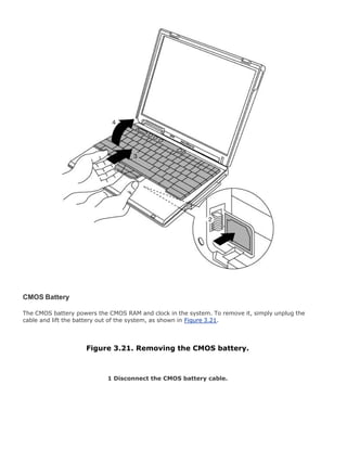
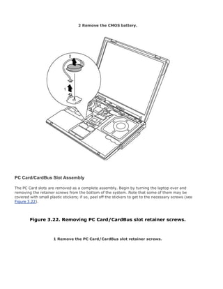
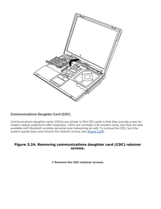
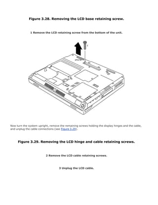
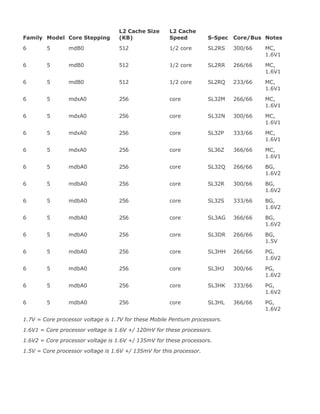
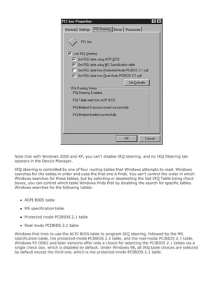
![Hitachi cancelled their 3" drive, forcing Gavilan to redesign the computer to accept the 3.5" format.
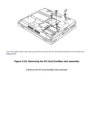
This redesign combined with cash flow problems caused Gavilan to file for bankruptcy before the
system could be introduced. After the floppy drive was changed, the Gavilan SC was finally released
in June 1984 for $3,995, but by then the company was under Chapter 11 protection, from which they
never fully recovered.
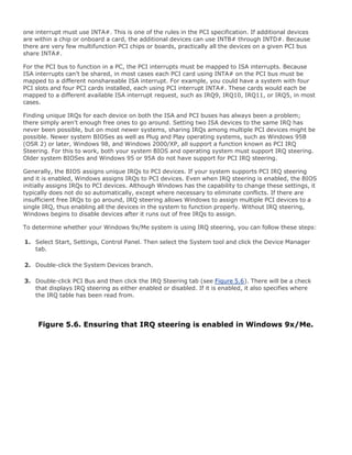
Notebooks
Notebook computers were originally described as being truly notebook sized, and generally used a
fixed screen that did not fold over the keyboard like the clamshell design used for laptops. Later the
notebook designation was used to describe a smaller, thinner, or lighter laptop (regardless of the
actual size relation to a true paper notebook).
Today the definition of notebook is muddled to the point where the term is used interchangeably with
the term laptop. In fact, pretty much all modern laptop computers are referred to as notebooks by
their manufacturers, regardless of the actual size, thickness, or weight. Throughout the book, you'll
see that I prefer the term laptop instead of notebook, since I find it more descriptive, and especially
more intuitive for others to understand.
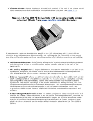
Epson HX-20
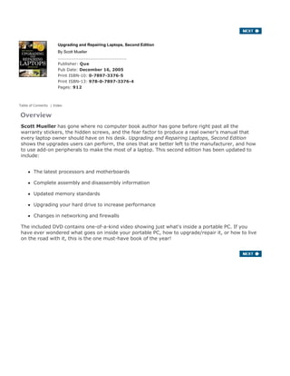
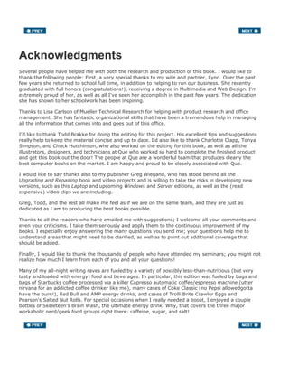
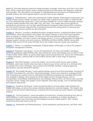
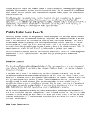
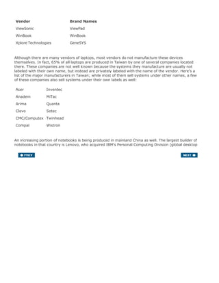
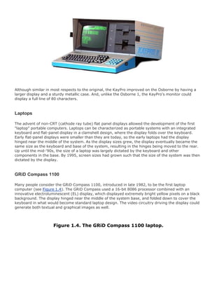
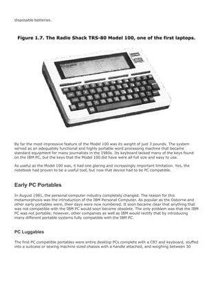
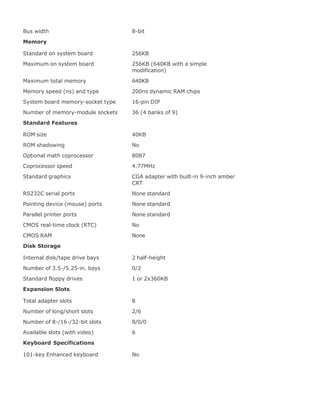
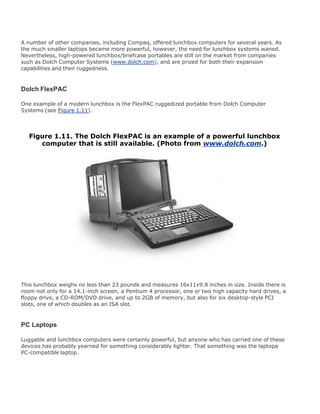
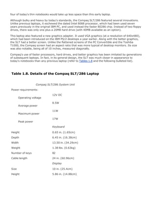
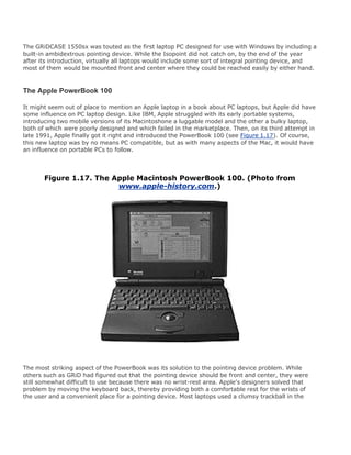
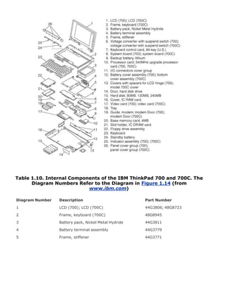
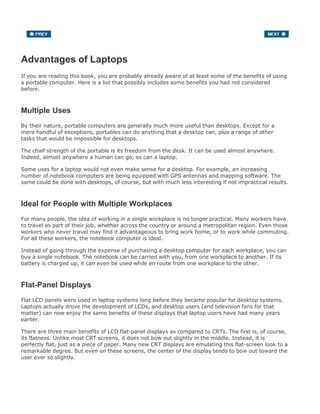
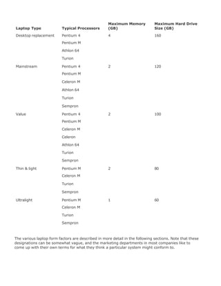
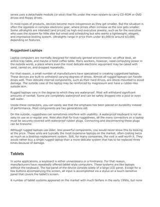
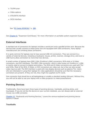
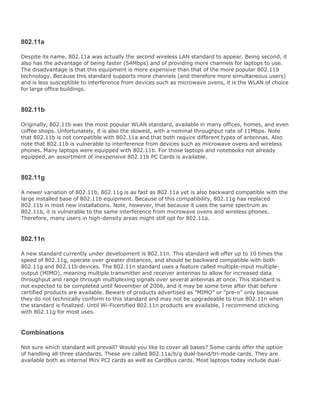
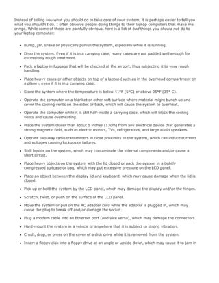
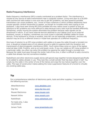
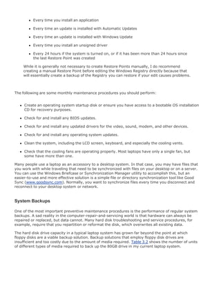
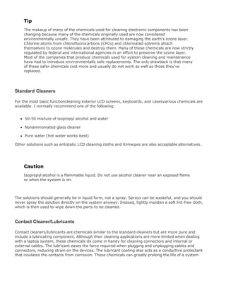
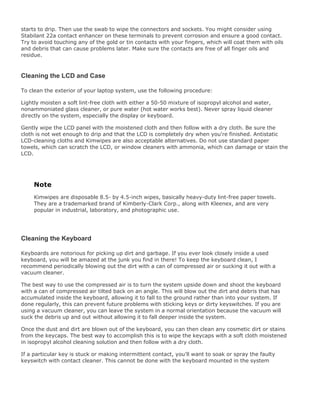
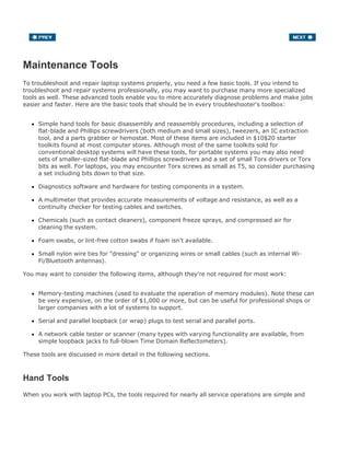
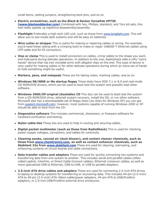
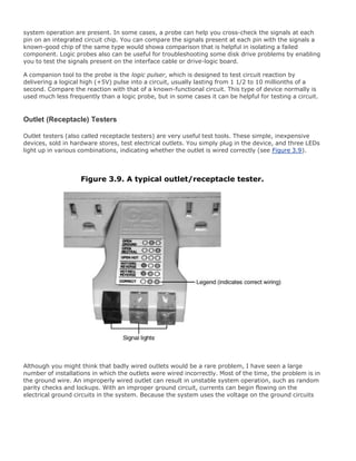
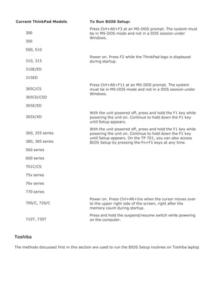
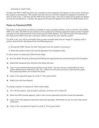
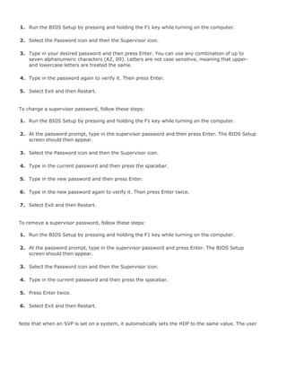
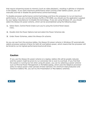
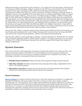
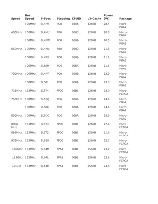
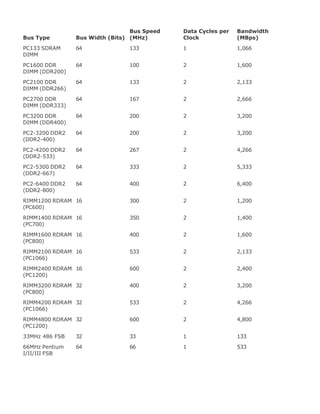
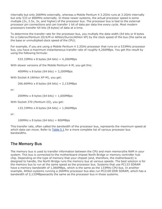
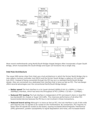
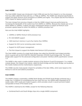
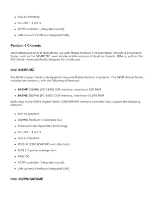
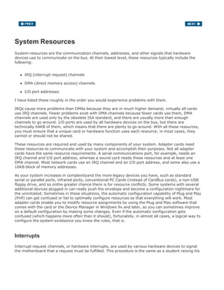
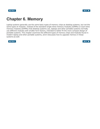
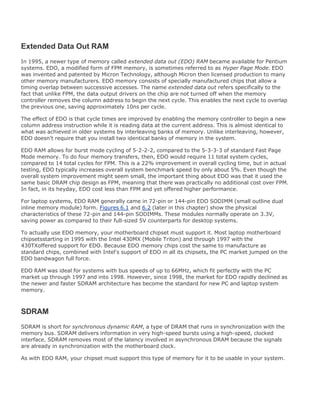
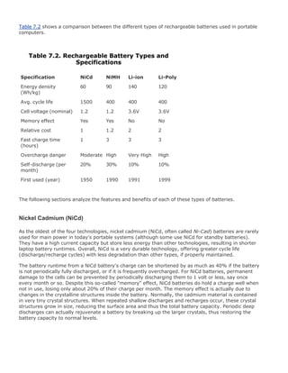
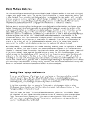
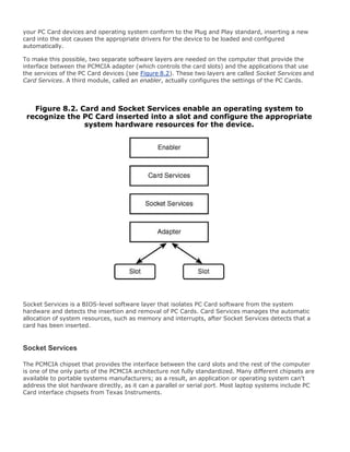
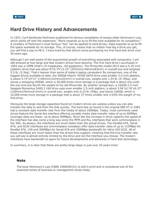
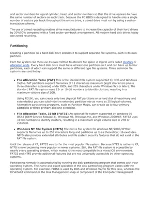
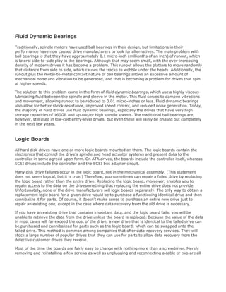
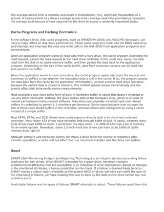
Epson introduced the HX-20 in November 1982, and advertised it as the world's first "notebook size"
portable computer. The HX-20 is 8.5" by 11.4" and 1.7" thick, which is almost exactly the length and
width of a standard sheet of notebook paper, thus making the notebook claim entirely true (see
Figure 1.6). It also weighed only 4 lbs., much lighter than the typical laptop.
Figure 1.6. The Epson HX-20 notebook. (Photo from
www.oldcomputers.net.)
[View full size image]](https://image.slidesharecdn.com/upgrading1-140602222156-phpapp02/85/Upgrading-1-laptop-2-th-33-320.jpg)
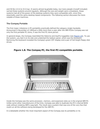
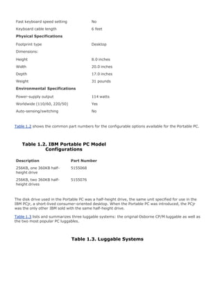
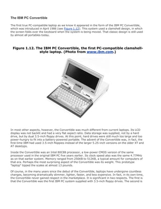
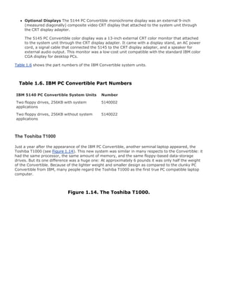
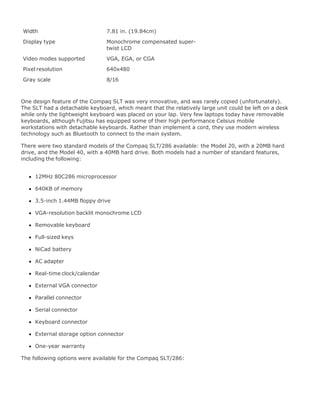
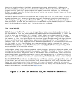
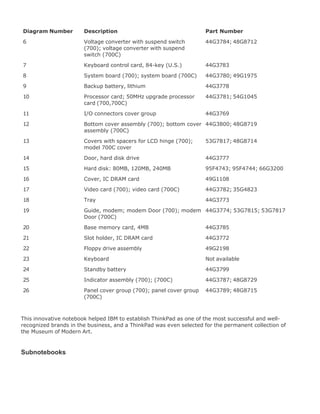

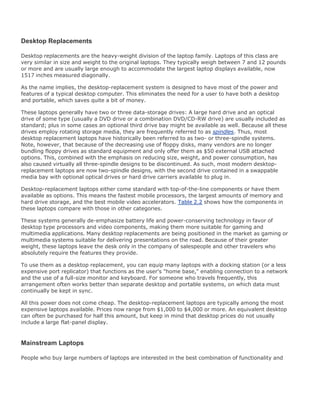
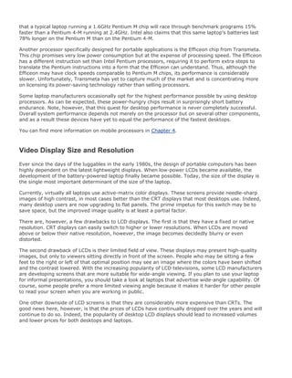
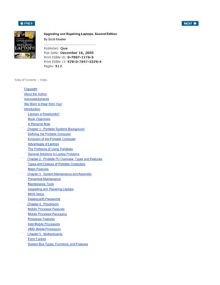
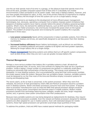
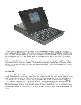
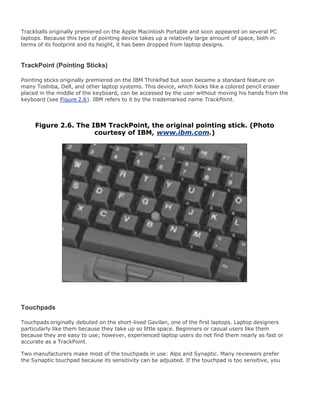
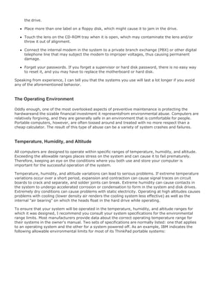
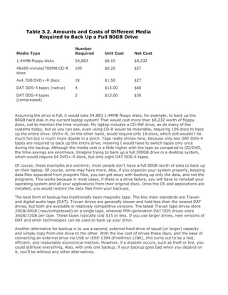
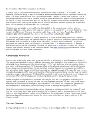
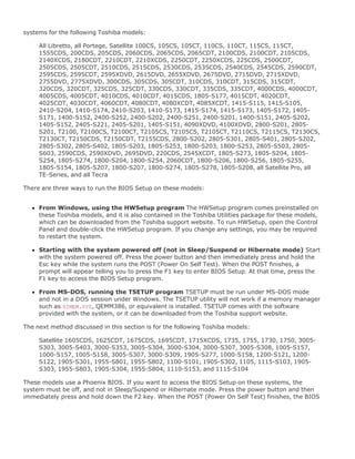
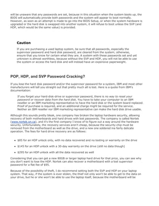
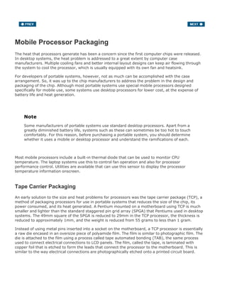
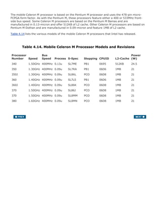
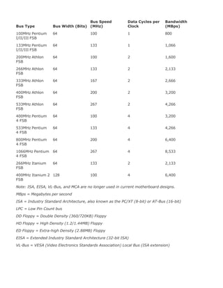
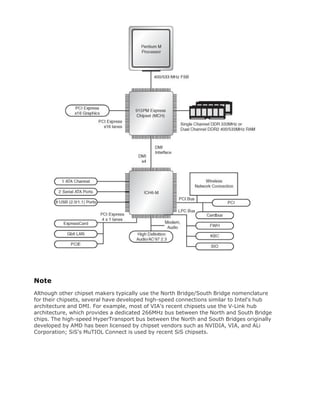
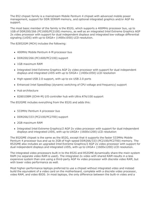
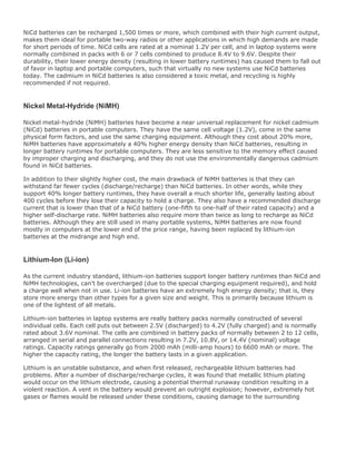
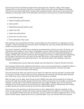
![(Photo courtesy of Dell Inc.)
[View full size image]
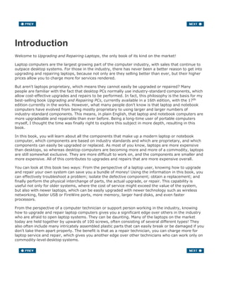
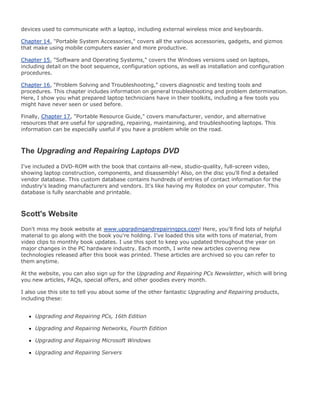
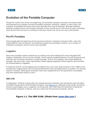
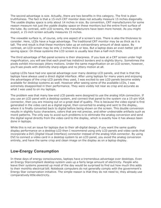
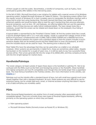
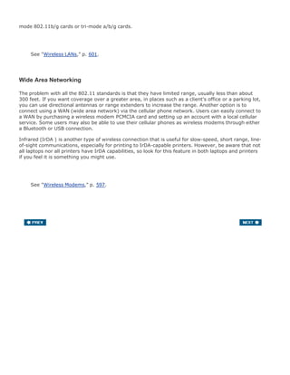
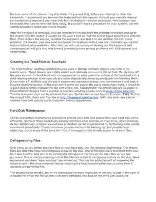
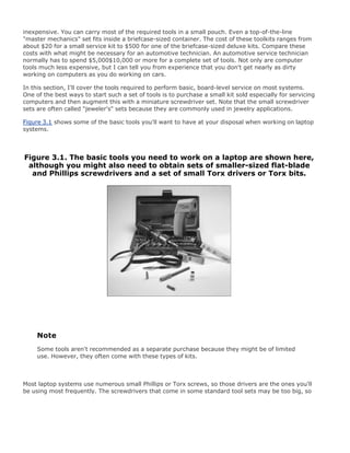
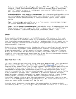
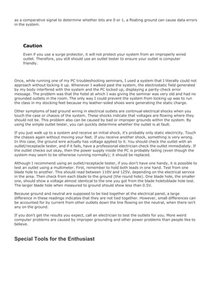
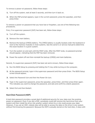
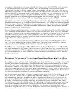
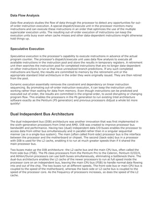
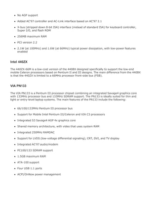
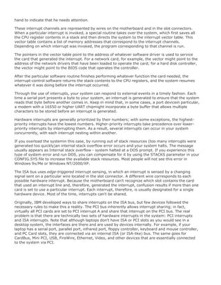
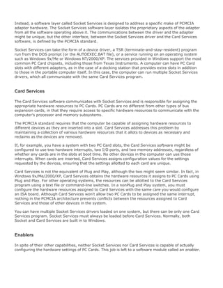
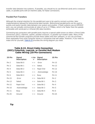
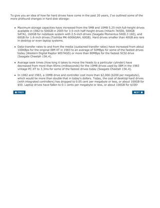
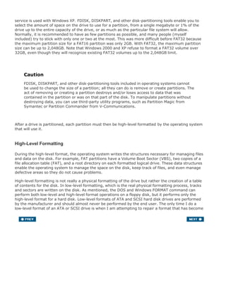
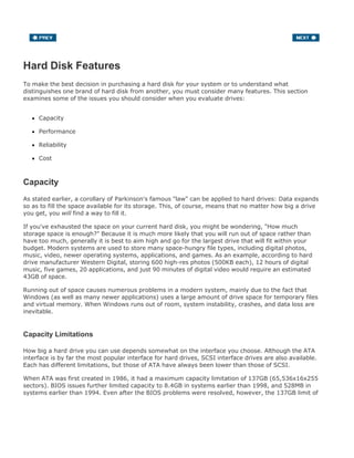
One interesting thing to note is that having a widescreen display doesn't necessarily mean you get
more resolution or desktop screen real estate. For example, many so-called "widescreen" laptops
have 15.4-inch WXGA (1280x800) displays. Personally, I would rather have a standard aspect ratio
15.1-inch SXGA+ (1400x1050) display because even though it doesn't have the "widescreen" aspect
ratio, it actually offers an overall wider and deeper image in pixels than the so-called widescreen
display. At the higher 1400x1050 pixel resolution, you'll actually be able to fit more open windows
(web pages, applications, and so on) both in width and depth than you could on a WXGA screen. In
fact, the SXGA+ screen has nearly 44% more overall resolution, meaning you can fit that much more
content on the screen. The primary advantage of using a widescreen on a laptop is that human vision
sees more peripherally than vertically, making wider screens better suited to what you actually see
on them.
Video Accelerators
A crucial and sometimes overlooked aspect of computer performance is the speed of its video](https://image.slidesharecdn.com/upgrading1-140602222156-phpapp02/85/Upgrading-1-laptop-2-th-92-320.jpg)
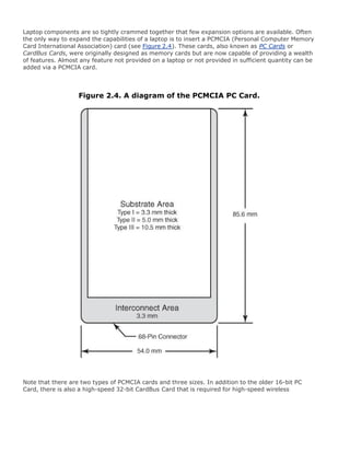
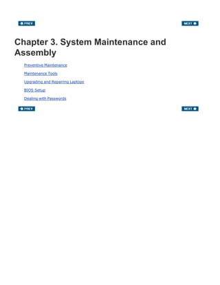
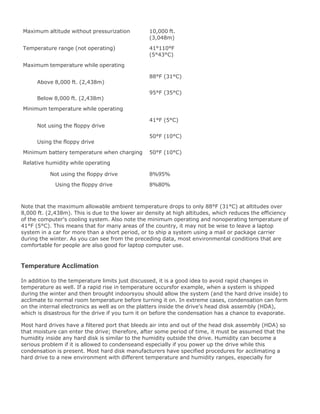
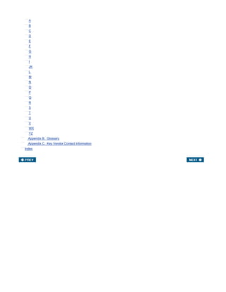
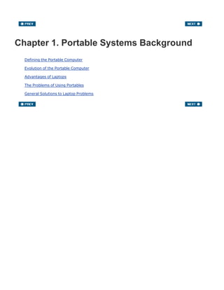
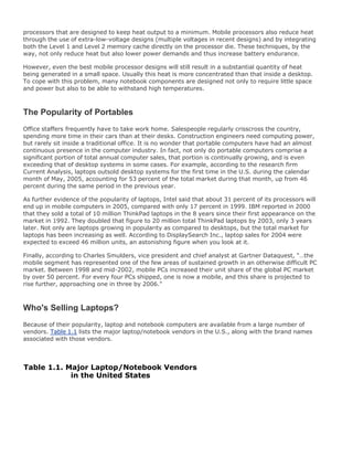
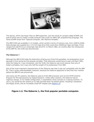
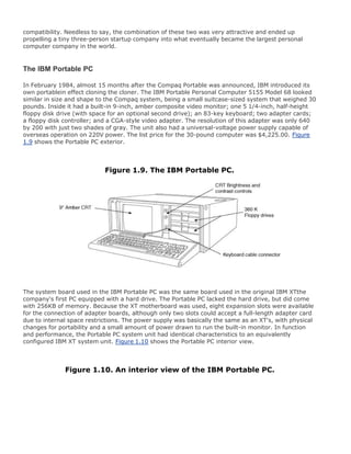
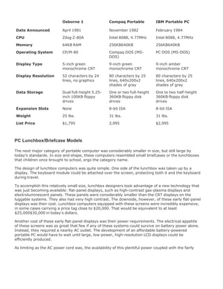
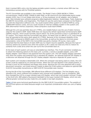
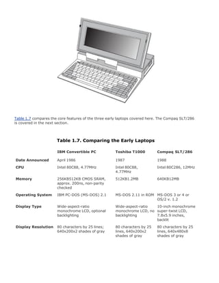
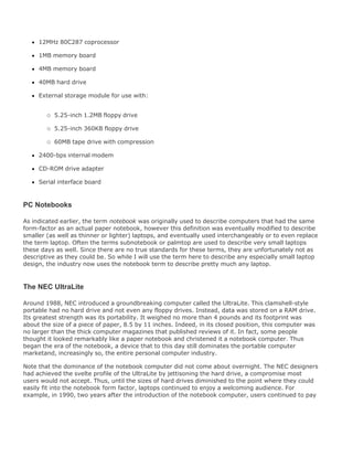
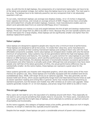
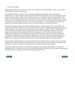
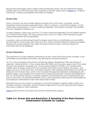
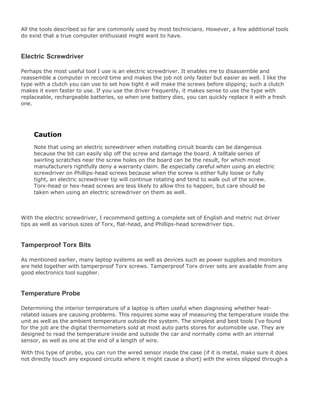
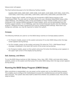
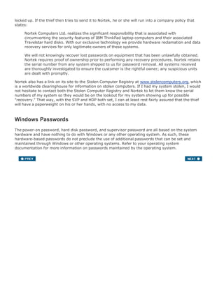
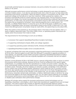
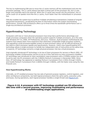
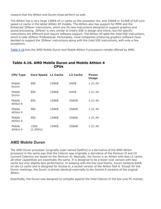
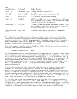
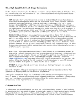
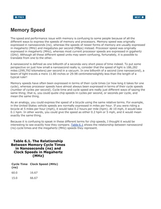
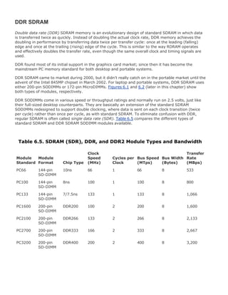
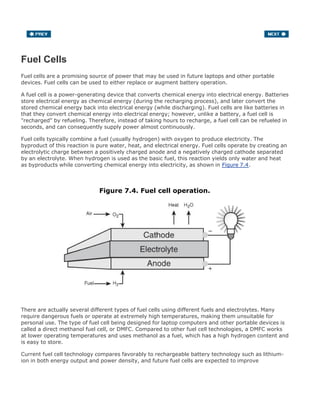
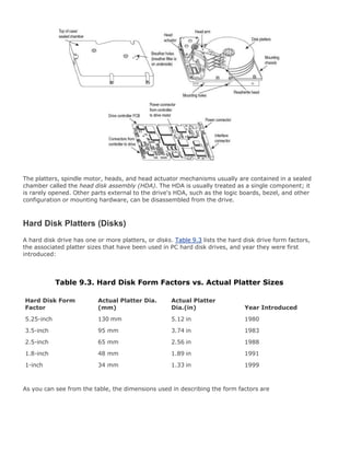
![Although a set of basic tools is useful, you should supplement your toolkit with some additional tools,
such as the following:
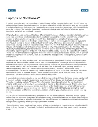
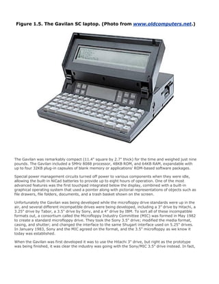
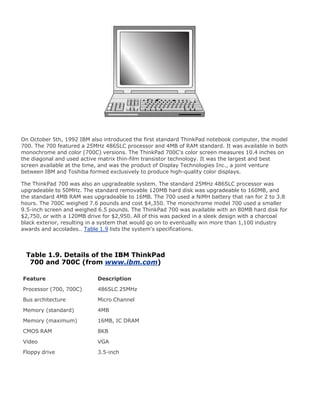
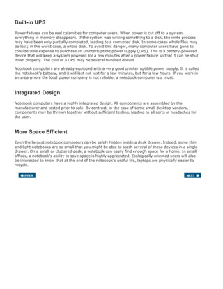
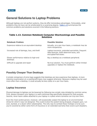
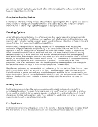
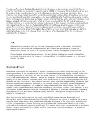
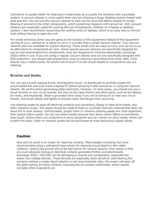
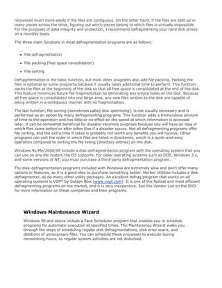
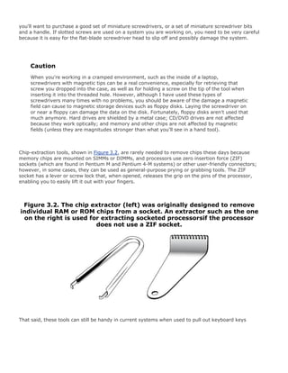
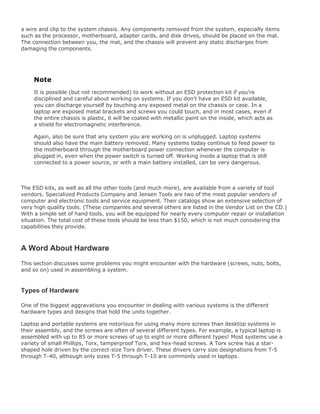
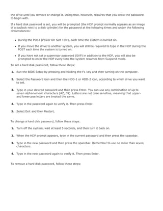
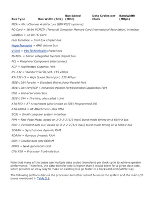
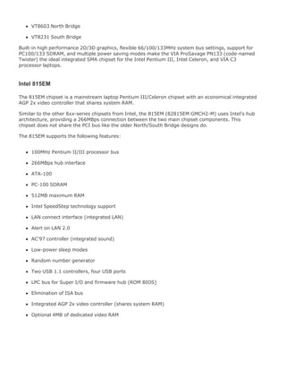
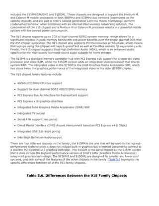
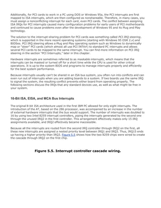
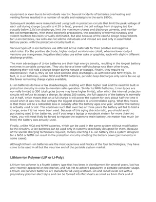
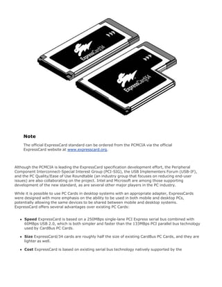
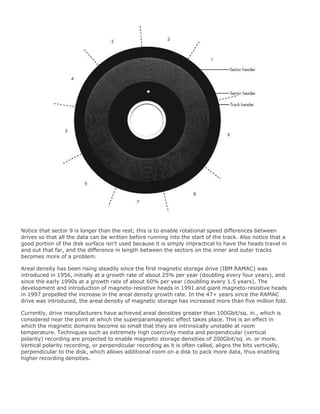
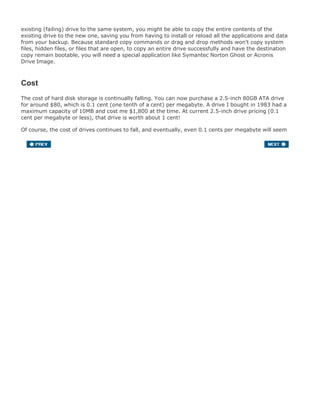
Electrostatic discharge (ESD) protection kit, including wrist strap and mat (such as
those from RadioShack or Jensen Tools) This kit prevents static damage to the
components you are working on. The kit consists of a wrist strap with a ground wire and a
specially conductive mat with its own ground wire. You also can get just the wrist strap or the
antistatic mat separately. In areas where there is low humidity (or during certain seasons of the
year), static charges are much more likely to build up as you move, increasing the need for ESD
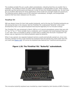
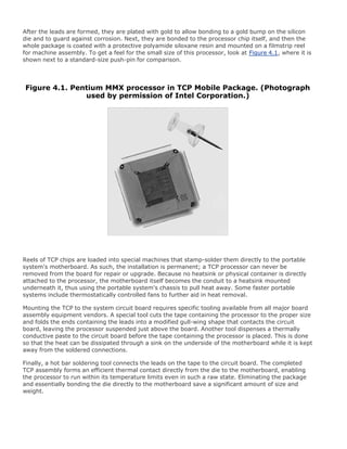
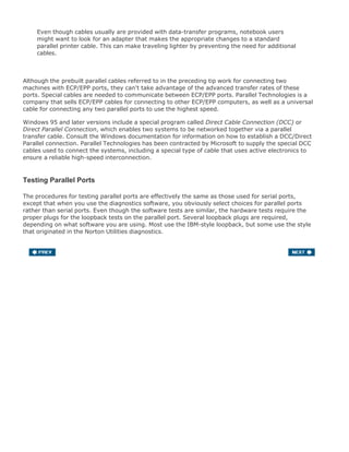
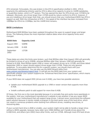
protection. A wrist strap is shown later in this chapter in Figure 3.5.
Figure 3.5. A typical ESD wrist strap; clip the end to a metallic
surface in the chassis.
[View full size image]
Needle-nose pliers and hemostats (curved and straight) These are great for gripping](https://image.slidesharecdn.com/upgrading1-140602222156-phpapp02/85/Upgrading-1-laptop-2-th-129-320.jpg)
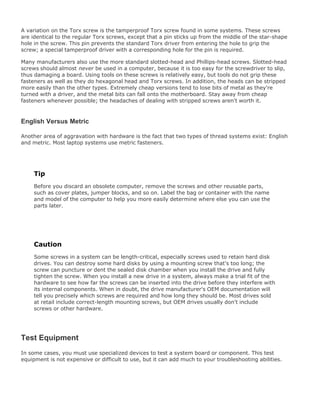
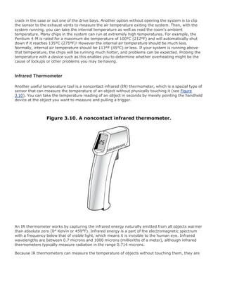

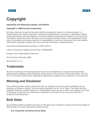
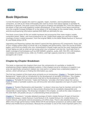
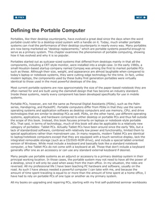
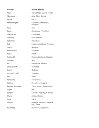
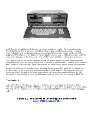
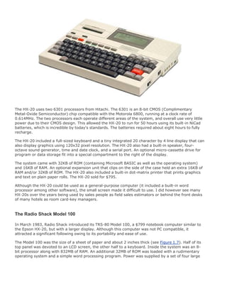
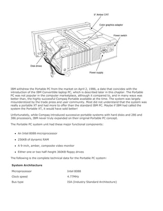
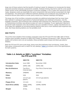
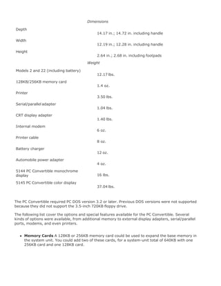
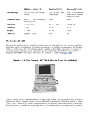
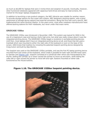
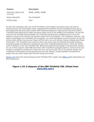
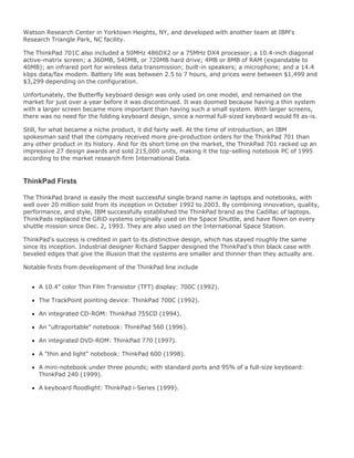
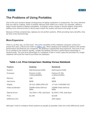
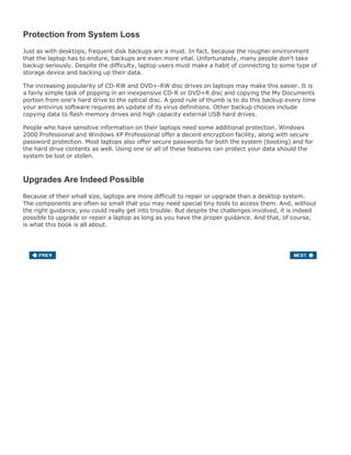
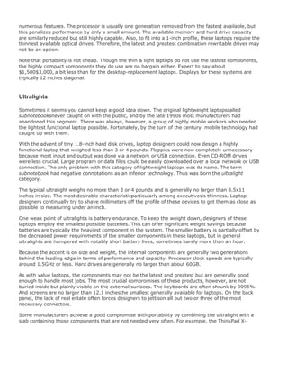
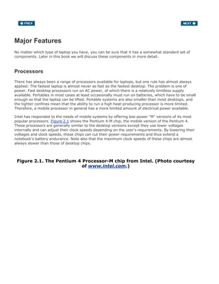
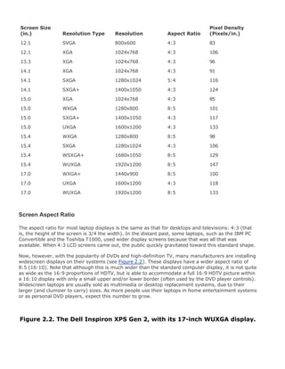
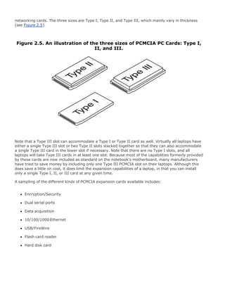
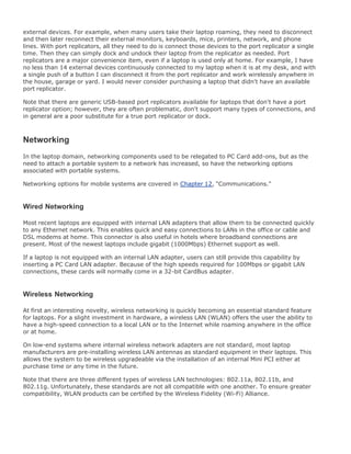
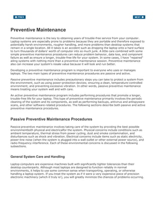
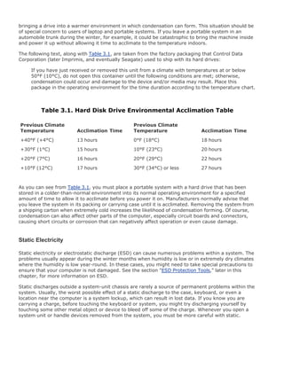
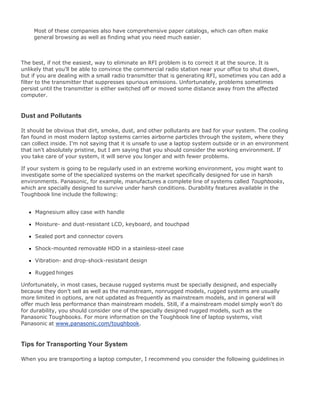
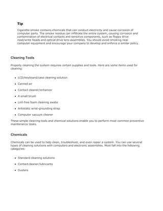
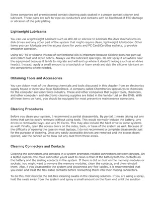
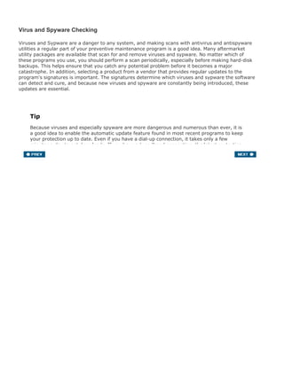
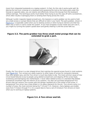
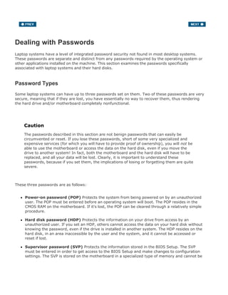
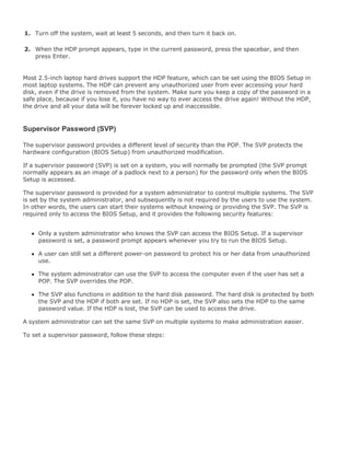
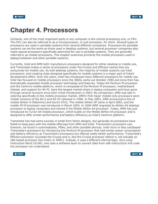
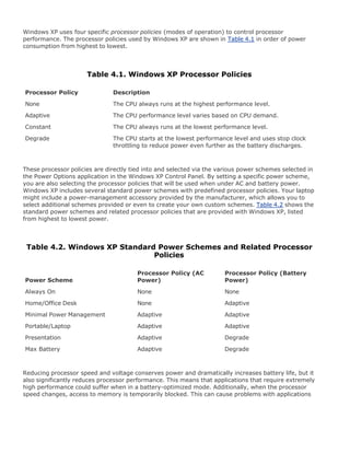
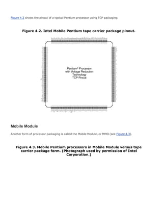
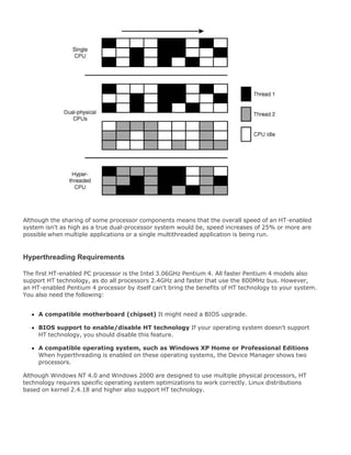
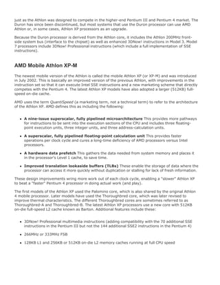
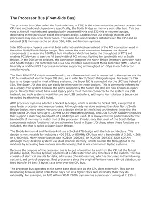
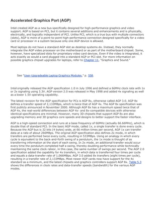
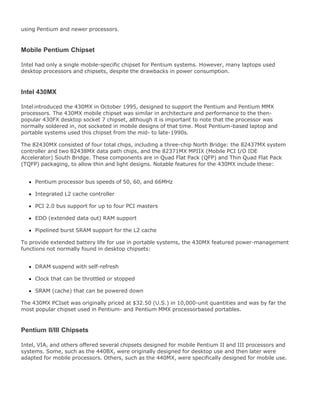
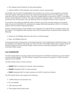
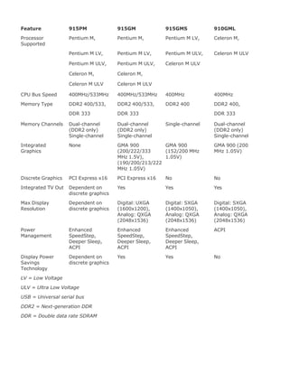
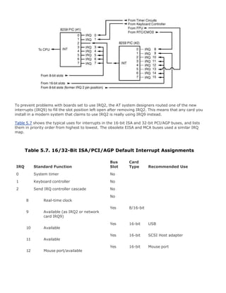
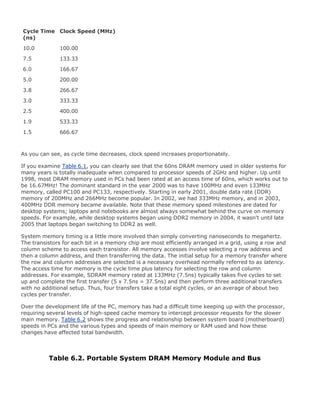
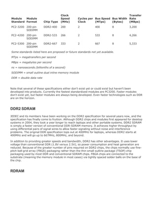
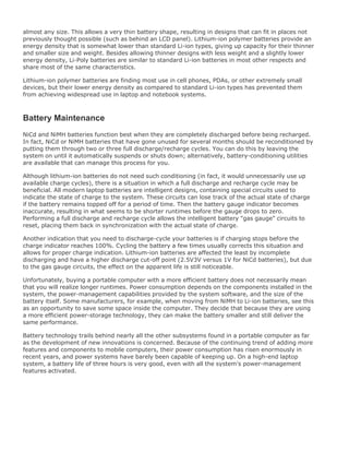
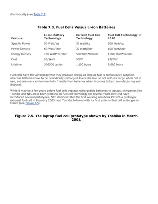
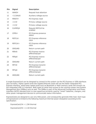
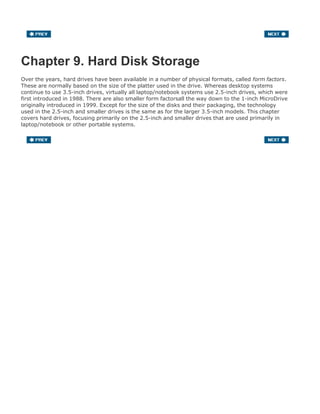
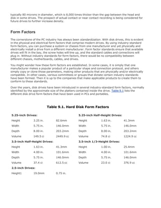
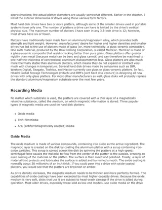
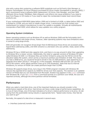
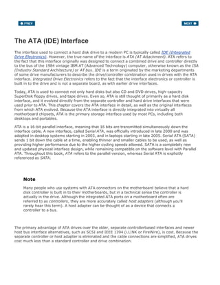
![There are always exceptions to the rule, of course. However, purchasing compatible components that
fit together properly is certainly more of a challenge for a portable system than it is for a desktop
system. Table 3.3 explains which laptop system components can be upgraded.
Table 3.3. Upgradeable Laptop System Components
Component Upgradeable Notes
Motherboard No Nonstandard form factors prevent internal upgrades.
CPU Yes Installing a faster CPU of the same type and model is
usually possible; however, there can be limitations due to
voltage, thermal, and/or BIOS support issues, and clock
speed increases will normally be small.
Memory Yes Normally, only one or two SIMM/DIMM sockets are
available. You may need to remove lower-capacity existing
modules to upgrade.
Video adapter/chipset No Video is integrated into a nonupgradeable motherboard.
Video display No[1] Nonstandard form factors and connections prevent internal
upgrades.
Keyboard/pointing
device
No[2] Nonstandard form factors and connections prevent internal
upgrades.
Hard disk Yes Older systems might not have BIOS support for drives
larger than 8.4GB. Many systems are limited to 9.5mm- or
12.5mm-thick drives. Drive trays or caddies are often
required for installation.
Removable-media
drives (floppy, CD/DVD,
CD-RW/DVD+-RW)
Yes Install these internally via modular bays or use externall
USB or IEEE 1394 (FireWire/i.LINK) drives.
USB, IEEE 1394
(FireWire/i.LINK), serial
(RS-232), parallel (IEEE
1284), SCSI, and so on
Yes Install these via PC Card/CardBus or ExpressCard
adapters.
10/100/1000Mbps
Ethernet LAN
Yes Install this via a PC Card or CardBus adapters.
Wireless 802.11a/b/g
(Wi-Fi), Bluetooth
Yes Install these via PC Card, CardBus, Mini PCI (internal)
cards, or mobile daughter cards (MDCs). Internal cards
may require preinstalled antennas.
[1] It is normally possible to connect an external display and use it in lieu of or in addition to the existing internal display.
[2] It is normally possible to connect an external keyboard and/or pointing device to use in lieu of or in addition to the existing
internal devices.](https://image.slidesharecdn.com/upgrading1-140602222156-phpapp02/85/Upgrading-1-laptop-2-th-144-320.jpg)


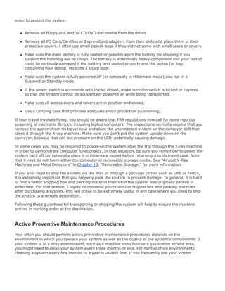
![A later version of the MMO is called the MMC, which stands for Mobile Module Connector and is
available in MMC-1 and MMC-2 versions. The original Celeron and Pentium II were available in MMC-1
and MMC-2 versions, whereas the Pentium III was released in the MMC-2 version only. The Pentium
II and III MMC-2 feature the Intel 440BX chipset's 82443BX host bridge, which connects to the
PIIX4E/M PCI/ISA South Bridge built in to the portable computer's motherboard.
In many ways, the MMO/MMC is similar to the Pentium II Single Edge Cartridge (SEC) design, but
with part of the motherboard included. The module interfaces electrically to its host system via a
3.3V PCI bus, a 3.3V memory bus, and Intel chipset control signals bridging the half of the chipset on
the module to the other half of the chipset on the system motherboard. The Intel Mobile Module also
incorporates a single thermal connection that carries all the module's thermal output to the mobile
PC's main cooling mechanisms.
The MMO is mounted with screws and alignment guides to secure the module against the typical
shock and vibration associated with mobile PC usage (see Figure 4.5). The MMO is 4 inches
(101.6mm) long x 2.5 inches (63.5mm) wide x 0.315 inch (8mm) high (0.39 inch or 10mm high at
the connector).
Figure 4.5. Intel Pentium MMX Mobile Module, including the processor,
chipset, and L2 cache. (Photograph used by permission of Intel
Corporation.)
[View full size image]](https://image.slidesharecdn.com/upgrading1-140602222156-phpapp02/85/Upgrading-1-laptop-2-th-197-320.jpg)
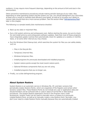
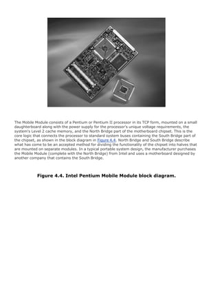
![The Mobile Module greatly simplifies the process of installing a Pentium III processor into a portable
system, permits manufacturers to build more standardization into their portable computer designs,
and eliminates the need for manufacturers to invest in the special tools needed to mount TCP
processors on circuit boards themselves. The module also provides a viable processor upgrade path
that was unavailable with a TCP processor permanently soldered to the motherboard. Portable
systems that offer a range of processor options use Mobile Modules because it enables the vendor to
use the same motherboard.
MMC-1
The Mobile Module Connector 1 (MMC-1) is an integrated assembly containing a Mobile Pentium II
processor, 256KB or 512KB of L2 cache, a 443BX North Bridge, and a voltage regulator supporting
input voltages from 5V to 21V. It is essentially most of a laptop motherboard in a single module (see
Figure 4.6). The MMC-1 has a 66MHz bus speed and was available in versions running at speeds of
up to 233, 266, 300, 333, 366, or 400MHz.
Figure 4.6. Intel Mobile Module Connector 1 (MMC-1), including the
processor/L2 cache, North Bridge chip, and voltage regulator.
(Photograph used by permission of Intel Corporation.)
[View full size image]](https://image.slidesharecdn.com/upgrading1-140602222156-phpapp02/85/Upgrading-1-laptop-2-th-198-320.jpg)
![The MMC-1 also includes a thermal transfer plate that is used for heatsink attachment, and it
incorporates thermal sensors for internal and external temperature sensing with programmable trip
points.
MMC-2
The Mobile Module Connector 2 (MMC-2) is an integrated assembly containing a Mobile Pentium II or
III processor, 256KB or 512KB of L2 cache, a 443BX North Bridge, and a voltage regulator supporting
input voltages from 5V to 21V. The MMC-2 has a 66MHz bus speed and was available in Pentium II
versions running at speeds of up to 400MHz, or Pentium III versions up to 700MHz.
The MMC-2 also includes a thermal transfer plate that is used for heatsink attachment, and it
incorporates thermal sensors for internal and external temperature sensing with programmable trip
points (see Figure 4.7).
Figure 4.7. Intel Mobile Module Connector 2 (MMC-2), including the
processor/L2 cache, North Bridge chip, and voltage regulator.
(Photograph used by permission of Intel Corporation.)
[View full size image]](https://image.slidesharecdn.com/upgrading1-140602222156-phpapp02/85/Upgrading-1-laptop-2-th-199-320.jpg)
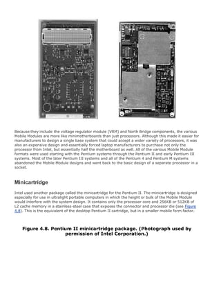
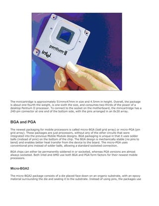
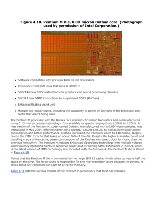
![The micro-FCBGA (flip chip ball grid array) package consists of a die placed face down on an organic
substrate, with an epoxy material surrounding the die and sealing it to the substrate (see Figure
4.11). The package uses 479 balls, which are 0.78mm in diameter and normally soldered directly to
the motherboard. Unlike micro-PGA, micro-FCBGA includes capacitors on the top side of the package.
Figure 4.11. Pentium III micro-FCBGA package. (Photograph used by
permission of Intel Corporation.)
[View full size image]
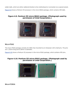
Micro-FCPGA and FCPGA2
The micro-FCPGA (flip chip pin grid array) and micro-FCPGA2 packages consist of a die placed face
down on an organic substrate, with an epoxy material surrounding the die and sealing it to the
substrate. The micro-FCPGA2 version includes a heat spreader (metal cap) over the top of the die for
additional mechanical strength and thermal management. Micro-FCPGA uses 478 pins, which are
2.03mm long and 0.32mm in diameter. Unlike micro-PGA2, micro-FCPGA and micro-FCPGA2 do not
use an interposer board and include capacitors on the bottom side. Even though the package has 478
pins, the socket supports 479 pins.
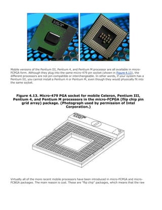
Figure 4.12 shows a Pentium III processor in the micro-FCPGA package. Note that the mobile
Celeron, Pentium 4, and Pentium M use the same packaging and look virtually identical.
Figure 4.12. Pentium III micro-FCPGA package (mobile Celeron, Pentium
4, and Pentium M look similar). (Photograph used by permission of Intel
Corporation.)
[View full size image]](https://image.slidesharecdn.com/upgrading1-140602222156-phpapp02/85/Upgrading-1-laptop-2-th-203-320.jpg)


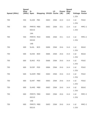
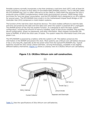
![Processor Voltage Core Speed
Bus
Speed
Manufacturing
Process
Core
Voltage
I/O
Buffer
Celeron 300MHz 66MHz 0.25 micron 1.6V 1.8V
Celeron 333MHz 66MHz 0.25 micron 1.6V 1.8V
Celeron 366MHz 66MHz 0.25 micron 1.6V 1.8V
Celeron 400MHz 66MHz 0.25 micron 1.6V 1.8V
Celeron 433MHz 66MHz 0.25 micron 1.9V 1.8V
Celeron 466MHz 66MHz 0.25 micron 1.9V 1.8V
Celeron 400MHz-LV 100MHz 0.18 micron 1.35V 1.5V
Celeron 450MHz 100MHz 0.18 micron 1.6V 1.5V
Celeron 500MHz-LV 100MHz 0.18 micron 1.35V 1.5V
Celeron 500MHz 100MHz 0.18 micron 1.6V 1.5V
Celeron 550MHz 100MHz 0.18 micron 1.6V 1.5V
Celeron 600MHz 100MHz 0.18 micron 1.6V 1.5V
Celeron 650MHz 100MHz 0.18 micron 1.6V 1.5V
Celeron 700MHz 100MHz 0.18 micron 1.6V 1.5V
Celeron 750MHz 100MHz 0.18 micron 1.6V 1.5V
Pentium III 400MHz 100MHz 0.18 micron 1.35V 1.5V
Pentium III 450MHz 100MHz 0.18 micron 1.6V 1.5V
Pentium III 500MHz 100MHz 0.18 micron 1.6V 1.5V
Pentium III 500MHz-ULV 100MHz 0.18 micron 1.1/0.975V[1] 1.5V
Pentium III 600MHz-LV 100MHz 0.18 micron 1.35/1.1V[1] 1.5V
Pentium III 600MHz 100MHz 0.18 micron 1.6/1.35V[1] 1.5V
Pentium III 650MHz 100MHz 0.18 micron 1.6/1.35V[1] 1.5V
Pentium III 700MHz 100MHz 0.18 micron 1.6/1.35V[1] 1.5V
Pentium III 700MHz-LV 100MHz 0.18 micron 1.35/1.1V[1] 1.5V
Pentium III 750MHz 100MHz 0.18 micron 1.6/1.35V[1] 1.5V
Pentium III 800MHz 100MHz 0.18 micron 1.6/1.35V[1] 1.5V
Pentium III 850MHz 100MHz 0.18 micron 1.6/1.35V[1] 1.5V
Pentium III 900MHz 100MHz 0.18 micron 1.7/1.35V[1] 1.5V
Pentium III 1GHz 100MHz 0.18 micron 1.7/1.35V[1] 1.5V
LV = Low Voltage](https://image.slidesharecdn.com/upgrading1-140602222156-phpapp02/85/Upgrading-1-laptop-2-th-218-320.jpg)
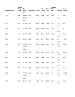
![Processor Voltage Core Speed
Bus
Speed
Manufacturing
Process
Core
Voltage
I/O
Buffer
ULV = Ultra Low Voltage
[1] Uses Intel SpeedStep technology, optionally switching to lower speed and voltage to conserve battery life
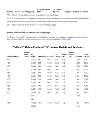
Mobile Pentium Processor Steppings
As with Intel's desktop processor, the chips of the mobile processor line undergo continual
development and are modified in the form of steppings that incorporate corrections and refinements
into the hardware-manufacturing process.
Note
The Mobile Pentium, Mobile Pentium MMX, and Mobile Pentium II processors are no longer
being produced, but you might still encounter them in the field.
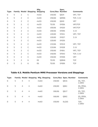
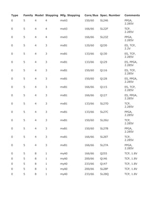
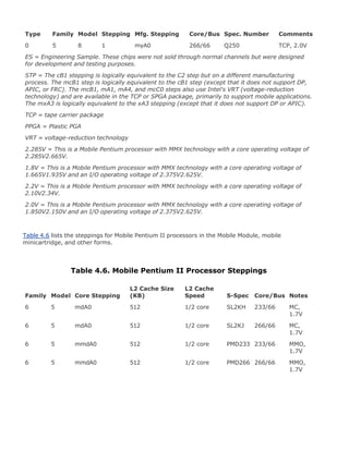
Tables 4.4 and 4.5 list various versions and steppings for the Mobile Pentium and Mobile Pentium
MMX processors.
Table 4.4. Mobile Pentium Processor Versions and Steppings
Type Family Model Stepping
Mfg.
Stepping Core/Bus
Spec.
Number Comments
0 5 2 1 B1 75/50 Q0601 TCP
0 5 2 2 B3 75/50 Q0606 TCP
0 5 2 2 B3 75/50 SX951 TCP
0/2 5 2 4 B5 75/50 Q0704 TCP
0 5 2 4 B5 75/50 SX975 TCP
0 5 2 5 C2 75/50 Q0725 TCP
0 5 2 5 C2 75/50 SK079 TCP
0 5 2 5 mA1 75/50 Q0686 VRT, TCP
0 5 2 5 mA1 75/50 Q0689 VRT](https://image.slidesharecdn.com/upgrading1-140602222156-phpapp02/85/Upgrading-1-laptop-2-th-219-320.jpg)
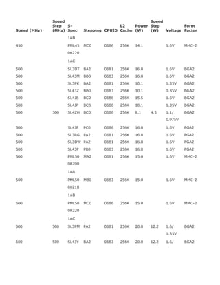
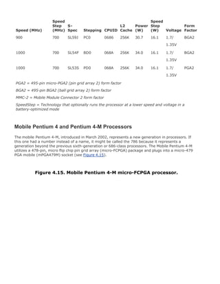
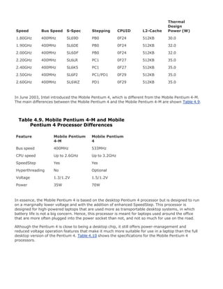
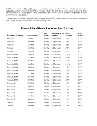
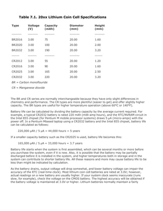
![Table 4.10. Mobile Pentium 4 Processor Specifications
CPU Max
Speed
CPU Min
Speed
CPU Bus
Speed S-Spec
Power
(Watts)
3.06GHz 1.6GHz 533MHz SL726 70
2.80GHz 1.6GHz 533MHz SL725 68.4
2.66GHz 1.6GHz 533MHz SL724 66.1
2.40GHz 1.6GHz 533MHz SL723 59.8
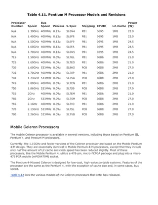
Pentium M
The Pentium M is the first Intel processor designed exclusively for mobile use. The Pentium M
processor (code-named Banias) was officially introduced in March 2003 along with the 855 chipset
family and the PRO/Wireless 2100 Mini PCI network adapter, which fall under what Intel calls the
Centrino brand name when combined in a single system. Today, these components have been
updated to offer either the Intel PRO/Wireless 2200BG or Intel PRO/Wireless 2915ABG network
adapter, able to connect to 802.11b/g or 802.11a/ b/g wireless networks, respectively. The 855
chipset has been superseded by the Mobile Intel 915 PCI Express chipset, offering DDR2 SDRAM and
PCI Express support. Figure 4.17 shows all of the components that make up the Centrino brand.
Figure 4.17. Pentium M and Centrino components. (Photograph used by
permission of Intel Corporation.)
[View full size image]](https://image.slidesharecdn.com/upgrading1-140602222156-phpapp02/85/Upgrading-1-laptop-2-th-236-320.jpg)
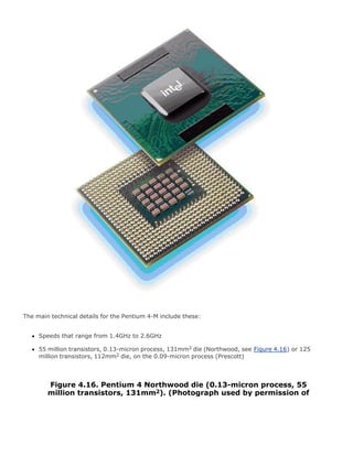
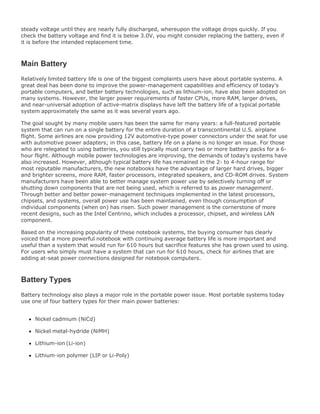
![AMD Mobile Processors
AMD has had a series of mobile processors, including several mobile versions of the K6, as well as the
Mobile Athlon 4, Mobile Duron, and Mobile Athlon XP-M. They are based on AMD's existing desktop
processors, with added features such as PowerNow! (processor performance control), which allows
for dynamically controlled speeds and voltage, as well as lower overall power consumption. Today,
AMD offers mobile versions of its Athlon 64 and Sempron processors, as well as a new platform
designed to compete with Intel's Centrino platform based on the AMD Turion 64 processor.
AMD K6-Series Mobile Processors
AMD's K6 series of processors has become popular among cost-conscious personal and corporate
computer buyers. These processors have dominated the under$1,000 computer market since the late
1990s. Starting in the fall of 1998, AMD began to develop this Socket 7compatible series of
processors for mobile use.
All mobile versions of the AMD K6 family share some common characteristics, including low-voltage
operation, MMX technology, and a choice of either ceramic pin grid array (CPGA) or the more
compact ceramic ball grid array (CBGA) packaging. Mobile K6 processors also have a large 64KB L1
memory cache, as their desktop siblings do.
Later versions of the Mobile K6 are called the K6-2+ and K6-III+. These new processors are both
made on a 0.18-micron technology process, enabling reduced die size and voltage. They also both
incorporate on-die L2 cache running at full processor speed and PowerNow! technology, which is
AMD's version of Intel's SpeedStep technology. This allows for lower speed and voltage operation
while on battery power to conserve battery life. The only difference between the K6-2+ and the K6-
III+ is the size of their on-die L2 caches. They both incorporate 64KB of L1 on-die: The K6-2+ adds a
further 128KB of on-die L2 cache, whereas the L2 size is increased to 256KB in the K6-3+.
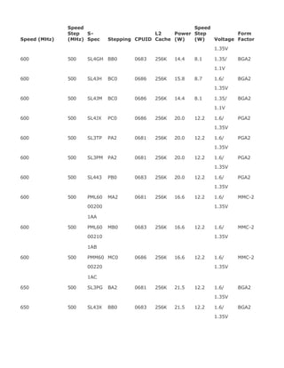
AMD offers the Mobile K6 family processors shown in Table 4.15.
Table 4.15. Mobile AMD K6 Family Processors
CPU Model Core Voltage Clock Speeds Notes
Mobile K6[*] 2.1V 233, 266 66
Mobile K6[*] 2.2V 300 66
Mobile K6-2[*] 1.71.9V 266, 300, 333, 350, 100, 3DN
366, 380
Mobile K6-2 2.02.2V 450, 500, 475 100, 3DN](https://image.slidesharecdn.com/upgrading1-140602222156-phpapp02/85/Upgrading-1-laptop-2-th-244-320.jpg)
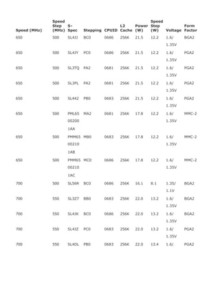
![CPU Model Core Voltage Clock Speeds Notes
1.92.1V 100, 3DN
Mobile K6-III[*] 2.2V 350, 366, 380 100, 256KL2, 3DN
Mobile K6-2P[*] 2.2V 400, 433, 450, 475 100, 3DN
Mobile K6-III+[#] 1.92.1V 450, 475, 500 100, 256KL2, 3DN
Mobile K6-2+[#] 1.92.1V 450, 475, 500, 533,
550
100, 128KL2, 3DN
66 = Has a 66MHz bus speed
100 = Has a 100MHz bus speed
256KL2 = Contains a 256KB integrated L2 cache running at full processor speed and supports L3
cache on the motherboard
3DN = Supports 3DNow! multimedia enhancements
[*] = Built with the .25-micron process
[#] = Built with the .18-micron process
AMD's Mobile Athlon and Athlon XP
Even though the K6 family of processors offers very good performance in its class, these processors
are not fast enough to compete with the 600MHz and higher Mobile Pentium III and Mobile Celeron
processors from Intel. In May 2001, AMD introduced its Mobile Athlon, known as the Athlon 4, and its
Mobile Duron processors, which, similar to their desktop siblings, directly compete with the Intel
Pentium III and Celeron processors.
The Athlon 4 features 256KB of on-die L2 cache and support for either PC-133 or DDR SDRAM. The
Athlon 4 uses 1.4V of power at full speed and 1.2V in battery-saving mode.
The Mobile Duron features 64KB of on-die L2 cache and uses the standard 200MHz FSB introduced by
the original Athlon CPU. The Mobile Duron uses 1.5V at full speed and 1.2V in battery-saving mode.
Both the Mobile Athlon 4 and the Mobile Duron use the 0.18-micron process, use a modified version
of the 462-pin Socket A used by desktop Athlon and Duron processors, and feature 128KB of Level 1
cache and an improved version of AMD's PowerNow! battery-saving technology.
The mobile Athlon uses a 200MHz or 266MHz processor (front-side) bus called the EV6 to connect to
the motherboard North Bridge chip as well as other processors. Licensed from Digital Equipment, the
EV6 bus is the same as that used for the Alpha 21264 processor, now owned by Compaq. The EV6
bus uses a clock speed of 100MHz or 133MHz, but it double-clocks the data, transferring data twice
per cycle, for a cycling speed of 200MHz or 266MHz. Because the bus is 8 bytes (64 bits) wide, this
results in a throughput of 8 bytes x 200MHz/266MHz, which amounts to 1.6GBps or 2.1GBps. This
bus is ideal for supporting PC1600 or PC2100 DDR memory, which also runs at those speeds. The
AMD bus design eliminates a potential bottleneck between the chipset and the processor, and enables
more efficient transfers compared to other processors. The use of the EV6 bus is one of the primary](https://image.slidesharecdn.com/upgrading1-140602222156-phpapp02/85/Upgrading-1-laptop-2-th-245-320.jpg)
![2000+
1900+
1800+
1700+
1600+
1500+
1400+
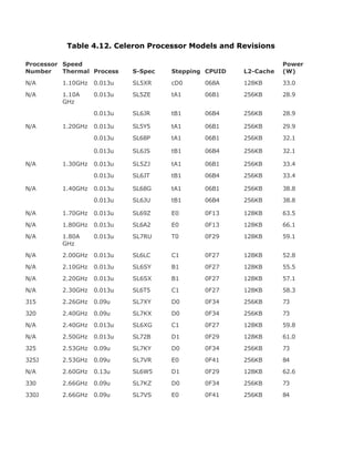
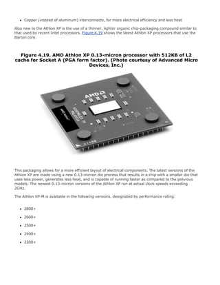
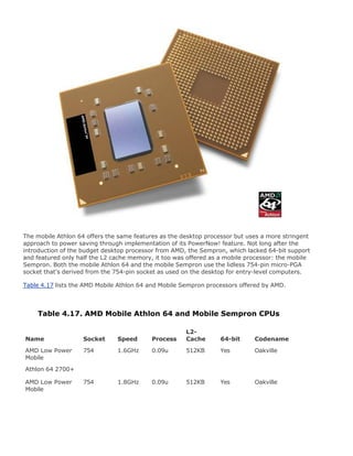
AMD Mobile Athlon 64 and Mobile Sempron
With AMD's introduction of the Athlon 64, the mobile version of that processor wasn't far off. Because
it is equipped with the same space-saving integrated memory controller as the desktop version of the
Athlon 64, the Mobile Athlon 64, shown in Figure 4.20, is ideally suited for use in the small confines of
a notebook.
Figure 4.20. The AMD Mobile Athlon 64 processor. (Photo courtesy of
AMD.)
[View full size image]](https://image.slidesharecdn.com/upgrading1-140602222156-phpapp02/85/Upgrading-1-laptop-2-th-249-320.jpg)
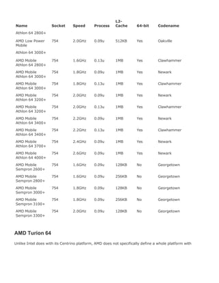
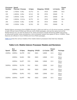
![the Turion brand name. Rather, the AMD Turion 64 processor, shown in Figure 4.21, is optimized for
use in mobile devices such as laptops, much like Intel's Pentium M processor. The AMD Turion 64
processor can be combined with a variety of different chipsets and wireless solutions from various
third-party manufacturers that allow it to offer similar performance and battery life as compared to
Intel's offering.
Figure 4.21. The AMD Turion 64 processor. (Photo courtesy of AMD.)
[View full size image]
The AMD Turion 64 processor is based on the same 64-bit core that can be found in the AMD Athlon
64 and Sempron processors and also incorporates the same integrated memory controller. Like these
other AMD processors, the Turion 64 offers compatibility with 32-bit and 64-bit operating systems
and is able to address over 4GB of memory directly. The AMD Turion 64 offers 3DNow! technology
and also supports SSE2 and SSE3. The AMD Turion 64 uses the same lidless 754-pin Micro-PGA
socket as the mobile Athlon 64 and Sempron.
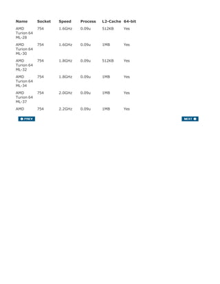
Table 4.18 lists the AMD Turion 64 processors offered by AMD.
Table 4.18. AMD Turion 64 Processors](https://image.slidesharecdn.com/upgrading1-140602222156-phpapp02/85/Upgrading-1-laptop-2-th-252-320.jpg)

![Socket Pins Pin Layout Voltage Supported Processors
MMC-1 280 70x4 5V-21V[*] Mobile
Pentium/Celeron/Pentium
II MMC-1
MMC-2 400 40x5 5V-21V[*] Mobile Celeron/Pentium
II/III MMC-2
MC 240 30x8 Auto VRM Mobile Pentium II MC
Micro-PGA1 615 24x26 mPGA Auto VRM Mobile Celeron/Pentium
II micro-PGA1
Micro-PGA2 495 21x24 mPGA Auto VRM Mobile Celeron/Pentium
III micro-PGA2
Socket 478 478 26x26 mPGA Auto VRM Desktop Celeron/Pentium
4 FC-PGA2
mPGA479M 479 26x26 mPGA Auto VRM Mobile Celeron/Pentium
III/4/M micro-FC-PGA
Socket A (462) 462 37x37 SPGA Auto VRM Mobile/Desktop
Duron/Athlon 4/Athlon
XP-M
Socket 754 754 29x29 mPGA Auto VRM Mobile/Desktop Athlon 64
Auto VRM = Voltage regulator module with automatic voltage selection determined by processor
VID pins
FC-PGA = Flip-chip pin grid array
PGA = Pin grid array
SPGA = Staggered pin grid array
mPGA = Micro-pin grid array
[*] Automatic voltage regulator module is built in to the MMC, allowing a wide range of voltage input
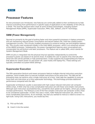
Note that some laptops use desktop processors, so they might use desktop processor sockets. Most,
however, use specific processors and sockets designed for mobile use. Just because a processor fits
into a particular socket does not mean that it will function. For example, versions of the Celeron,
Pentium III, Pentium 4, and Pentium M all plug into an mPGA479M socket, but only the one that the
system is designed for will work; in fact, plugging in the wrong one could cause damage. Despite
having similar pin counts and physical arrangements, the actual pinouts vary among the different
processors.
Chipsets
We can't talk about modern motherboards without discussing chipsets. The chipset is the
motherboard; therefore, any two boards with the same chipsets are functionally identical. The chipset](https://image.slidesharecdn.com/upgrading1-140602222156-phpapp02/85/Upgrading-1-laptop-2-th-275-320.jpg)
![chip.
The North Bridge is sometimes referred to as the PCI/AGP controller (PAC). It is essentially the main
component of the motherboard and is the only motherboard circuit besides the processor that
normally runs at full motherboard (processor bus) speed. Most modern chipsets use a single-chip
North Bridge; however, some of the older ones actually consisted of up to three individual chips to
make up the complete North Bridge circuit.
The South Bridge is the lower-speed component in the chipset and has always been a single
individual chip. The South Bridge is a somewhat interchangeable component, in that different chipsets
(North Bridge chips) often are designed to use the same South Bridge component. This modular
design of the chipset allows for lower cost and greater flexibility for motherboard manufacturers. The
South Bridge also typically contains dual ATA interfaces, several USB interfaces, and even the CMOS
RAM and real-time clock functions. The South Bridge contains all the components that make up the
ISA bus, including the interrupt and DMA controllers.
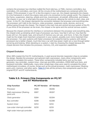
The third motherboard component, the Super I/O chip, is connected to the 8MHz ISA bus and
contains all the standard peripherals that are built in to a motherboard. For example, most Super I/O
chips contain the serial ports, parallel port, floppy controller, and keyboard/mouse interface.
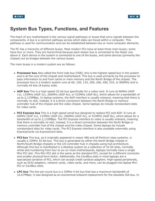
Figure 5.1 shows a typical North/South Bridge architecture using the 440BX chipset. This was the
most popular chipset and system architecture for late Pentium II or early Pentium III laptops.
Figure 5.1. Typical 440BX chipset laptop motherboard block diagram.
[View full size image]](https://image.slidesharecdn.com/upgrading1-140602222156-phpapp02/85/Upgrading-1-laptop-2-th-280-320.jpg)
![manufacturing costs.
This hub interface design allows for a much greater throughput for PCI devices because no South
Bridge chip (also carrying traffic from the Super I/O chip) is hogging the PCI bus. Because of
bypassing PCI, hub architecture also enables greater throughput for devices directly connected to the
I/O controller hub (formerly the South Bridge), such as the new higher-speed ATA-100/133, Serial
ATA, and USB 2.0 interfaces.
The hub interface design is also very economical, at only 8 bits wide. Although this seems too narrow
to be useful, there is a reason for the design. Because the interface is only 8 bits wide, it uses only 15
signals, compared to the 64 signals required by the 32-bitwide PCI bus interface used by North/South
Bridge chip designs. The lower pin count means that less circuit routing exists on the board, less
signal noise and jitter occur, and the chips themselves have fewer pins, making them smaller and
more economical to produce.
Although it transfers only 8 bits at a time, the hub interface executes four transfers per cycle and
cycles at 66MHz. This gives it an effective throughput of 4 x 66MHz x 1 byte = 266MBps. This is twice
the bandwidth of PCI, which is 32 bits wide but runs only one transfer per 33MHz cycles, for a total
bandwidth of 133MBps. So, by virtue of a very narrowbut very fastdesign, the hub interface achieves
high performance with less cost and more signal integrity than with the previous North/South Bridge
design.
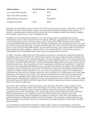
The MCH interfaces between the high-speed processor bus (800/533/400/133/100/66MHz) and the
hub interface (66MHz) and AGP bus (533/266/133/66MHz), whereas the ICH interfaces between the
hub interface (66MHz) and the ATA(IDE) ports (66/100MHz) and PCI bus (33MHz).
The ICH also includes a new Low Pin Count (LPC) bus, consisting basically of a stripped 4-bitwide
version of PCI designed primarily to support the motherboard ROM BIOS and Super I/O chips.
Because it uses the same 4 signals for data, address, and command functions, only 9 other signals
are necessary to implement the bus, for a total of only 13 signals. This dramatically reduces the
number of traces connecting the ROM BIOS chip and Super I/O chips in a system, compared to the
96 ISA bus signals necessary for older North/South Bridge chipsets that used ISA as the interface to
those devices. The LPC bus has a maximum bandwidth of 16.67MBps, which is faster than ISA and
more than enough to support devices such as ROM BIOS and Super I/O chips.
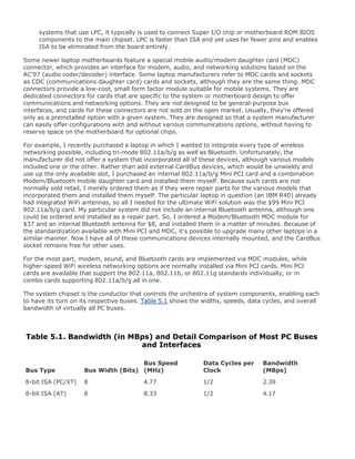
Figure 5.2 shows a typical hub interface architecture using the 855PM chipset. This is the most
popular chipset and system architecture for Pentium M laptops, and it represents a modern state-of-
the-art system design.
Figure 5.2. Typical 855PM chipset laptop motherboard block diagram.
[View full size image]](https://image.slidesharecdn.com/upgrading1-140602222156-phpapp02/85/Upgrading-1-laptop-2-th-282-320.jpg)
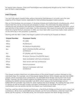
![Intel DMI Architecture
The 900 series chipsets from Intel have abandoned the hub interface in favor of a new interface
called Direct Media Interface (DMI). DMI is basically a modified PCI Express x4 (4-lane) interface
supporting a throughput of 1GBps in each direction simultaneously. Being a dedicated connection
between the chips in the chipset, DMI incorporates all of the same advantages of the former hub
interface, along with a significantly higher-speed interconnection. Figure 5.3 shows where DMI fits
into the 915 chipset between the 915PM memory controller hub (MCH) and the ICH6-M I/O controller
hub.
Figure 5.3. Typical 915PM chipset laptop motherboard block diagram.
[View full size image]](https://image.slidesharecdn.com/upgrading1-140602222156-phpapp02/85/Upgrading-1-laptop-2-th-283-320.jpg)
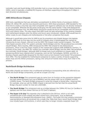
![separate video card (as in a desktop system) is that the built-in video card merely shares real estate
with the rest of the motherboard.
The 852PM chipset is the same as the 852GME (faster 533MHz processor bus and up to 2GB of high-
speed DDR266/333 [PC2100/PC2700] memory), but it lacks the integrated video. Instead, an AGP 4x
interface is included for connecting to third-party video processors. This makes the 852PM the best
choice for high-performance mobile Pentium 4 systems.
Pentium M Chipsets
Intel 855PM/GM
The Intel 855 chipset family is designed to support the 400MHz bus versions of the Pentium M and
Celeron M mobile processors and is part of Intel's Centrino Mobile Technology platform when
combined with an Intel wireless networking solution (see Figure 5.2). The combination of the 855
chipset and a Pentium M or Celeron M processor results in a powerful mobile system with low overall
power consumption.
The 855PM is a standard memory controller hub with AGP 4x support for a discrete video processor
and video RAM, while the 855GM version adds an integrated video processor that shares system
RAM.
The 855PM includes the following features:
400MHz Pentium M processor bus
2GB maximum RAM
DDR200/266 memory technology
High-speed USB 2.0 support with up to six USB 2.0 ports
AGP 4x interface
Dynamic input/output buffer disabling for processor system bus and memory, which reduces
chipset power consumption by activation or powerdown of the processor system bus or memory
Hub interface
82801DBM (ICH4-M) I/O controller hub
The 855GM includes everything from the 855PM and also adds an Integrated Intel Extreme
Graphics/2 AGP 2x video processor with support for dual independent displays and integrated low-
voltage differential signaling (LVDS), with up to UXGA+ (1600x1200) LCD resolution.
Intel 915 Express Chipset Family
The Intel 915 mobile chipset family (code-named Alviso) was introduced in January 2005 and](https://image.slidesharecdn.com/upgrading1-140602222156-phpapp02/85/Upgrading-1-laptop-2-th-293-320.jpg)


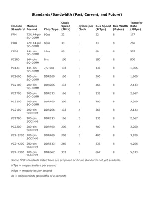
![total of five cycles (on a 66MHz bus, this is about 75ns total or 5 x 15ns cycles), and the consecutive
cycles take three cycles each (3 x 15ns = 45ns). As you can see, the actual system timing is
somewhat less than the memory is technically rated for. Without the bursting technique, memory
access would be 5-5-5-5 because the full latency is necessary for each memory transfer.
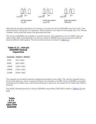
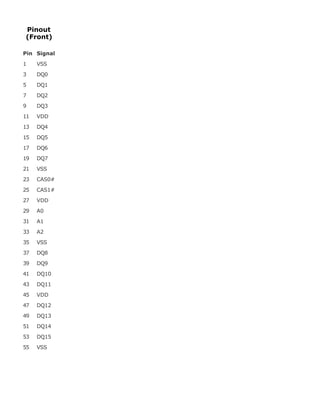
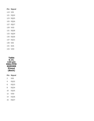
For laptop systems, FPM RAM generally came in 72-pin or 144-pin EDO SODIMM (small outline dual
inline memory module) form. Figures 6.1 and 6.2 (later in this chapter) show the physical
characteristics of these 72-pin and 144-pin SODIMMs. These modules normally operate on 3.3V,
saving power as compared to their full-sized 5V counterparts for desktop systems.
Figure 6.1. 72-pin SODIMM.
[View full size image]
Figure 6.2. 144-pin SODIMM.
[View full size image]](https://image.slidesharecdn.com/upgrading1-140602222156-phpapp02/85/Upgrading-1-laptop-2-th-328-320.jpg)

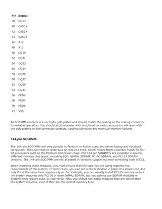
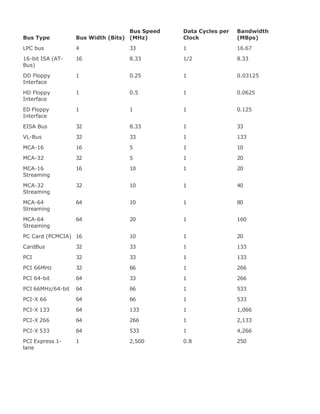
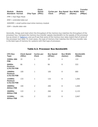
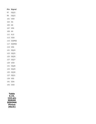
![The speeds of 144-pin SODIMMs are rated as shown in Table 6.10.
Table 6.10. 144-pin SDRAM SODIMM Speeds
Module Type Cycle Time
Module
Frequency Module Width
Module
Bandwidth
PC66 10.0ns 66MHz 8 bytes 533MBps
PC100 8.0ns 100MHz 8 bytes 800MBps
PC133 7.5ns 133MHz 8 bytes 1,066MBps
The throughput or bandwidth is simply the frequency multiplied by the width, which gives the rate at
which data can be read from or written to the module.
Another specification to consider that is related to speed is the CAS (column address strobe) Latency,
often abbreviated as CL. This is also sometimes called read latency, and it's the number of clock
cycles occurring between the registration of the CAS signal and the resultant output data, with lower
numbers of cycles indicating faster (better) performance. Typically, you find SDRAM modules rated
CL 2 or CL 3. If possible, choose modules with a lower CL figure, because the motherboard chipset
will read that specification out of the serial presence detect (SPD) ROM on the module and switch to
slightly faster cycling rates.
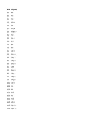
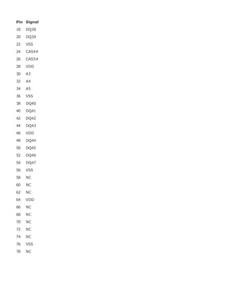
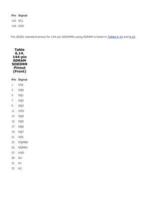
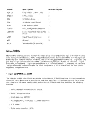
The 144-pin SODIMMs have the industry-standard form factor shown in Figure 6.2.
All 144-pin SODIMMs have the odd-numbered pins (1143) on the front and even-numbered pins
(2144) on the back and are 2.66" (67.6mm) long. The number of actual chips on the modules can
vary, as can the physical height of the module. The modules are normally either 1" (25.4mm) or
1.25" (31.75mm) high, although the heights may vary slightly.
The 144-pin SODIMMs use an SPD ROM (read-only memory) onboard, which the motherboard reads
to determine the exact specifications of the modules installed. The ROM is normally a small chip on
the module and can be seen as component "U1" in Figure 6.2.
The modules are keyed via a small notch in the connector area on the bottom (seen between pins 59
and 61 on the front), which prevents them from being installed backward and provides voltage
keying as well. The voltage keying is shown Figure 6.3.
Figure 6.3. 144-pin SODIMM voltage keying.
[View full size image]](https://image.slidesharecdn.com/upgrading1-140602222156-phpapp02/85/Upgrading-1-laptop-2-th-339-320.jpg)


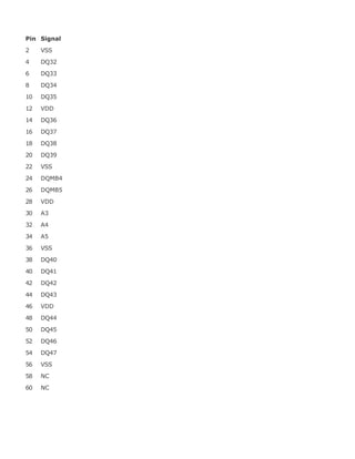
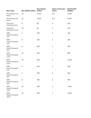
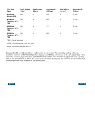
![system requires PC2700, you should not install the slower PC2100 or PC1600 modules.
The speeds of 200-pin SODIMMs are rated as shown in Table 6.16.
Table 6.16. 200-pin DDR2/DDR SDRAM SODIMM Speeds
Module Type
Module
Speed Cycle Time
Frequency
SDR/DDR Module Width
Module
Bandwidth
DDR2 PC2-5300 3.0ns 333/667MHz 8 bytes 5,333MBps
DDR2 PC2-4200 3.8ns 266/533MHz 8 bytes 4,266MBps
DDR2 PC2-3200 5.0ns 200/400MHz 8 bytes 3,200MBps
DDR PC3200 5.0ns 200/400MHz 8 bytes 3,200MBps
DDR PC2700 6.0ns 166/333MHz 8 bytes 2,667MBps
DDR PC2100 7.5ns 133/266MHz 8 bytes 2,133MBps
DDR PC1600 10.0ns 100/200MHz 8 bytes 1,600MBps
The cycle time in nanoseconds (billionths of a second) matches the single data rate (SDR) clock
speed, but double data rate (DDR) modules transfer twice per cycle, so the DDR frequency is always
equal to double the SDR frequency. The throughput or bandwidth is simply the DDR frequency times
the width, which gives the rate at which data can be read from or written to the module.
Another specification to consider that is related to speed is the CAS (column address strobe) Latency,
often abbreviated as CL. This is also sometimes called read latency, and it's the number of clock
cycles occurring between the registration of the CAS signal and the resultant output data, with lower
numbers of cycles indicating faster (better) performance. Typically, you can find DDR SDRAM
modules rated CL 2 or CL 2.5. If possible, choose modules with a lower CL figure, because the
motherboard chipset will read that specification out of the SPD (serial presence detect) ROM on the
module and switch to slightly faster cycling rates.
The 200-pin SODIMMs have the JEDEC industry-standard form factor shown in Figures 6.4 (DDR) and
6.5 (DDR2).
Figure 6.4. 200-pin DDR SDRAM SODIMM.
[View full size image]](https://image.slidesharecdn.com/upgrading1-140602222156-phpapp02/85/Upgrading-1-laptop-2-th-352-320.jpg)
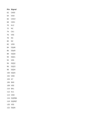
![Figure 6.5. 200-pin DDR2 SDRAM SODIMM.
[View full size image]
Note that the physical form factors for DDR and DDR2 are the same, except for the location of the
key notch in the module. This prevents DDR modules from being installed in place of DDR2 modules
and vice-versa.
All 200-pin SODIMMs have the odd-numbered pins (1199) on the front and even-numbered pins
(2200) on the back and are 2.66" (67.6mm) long. The number of actual chips on the module can
vary, as can the physical height of the module. The modules are normally either 1" (25.4mm) or
1.25" (31.75mm) high, although some versions can be up to 1.5" (38.1mm) high (the heights may
vary slightly). The taller modules may not fit in all systems, so be sure to check before ordering.
Although the 200-pin modules are the same physical size as 144-pin modules, the pin spacing is](https://image.slidesharecdn.com/upgrading1-140602222156-phpapp02/85/Upgrading-1-laptop-2-th-353-320.jpg)
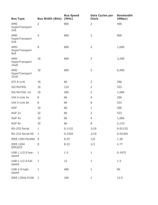
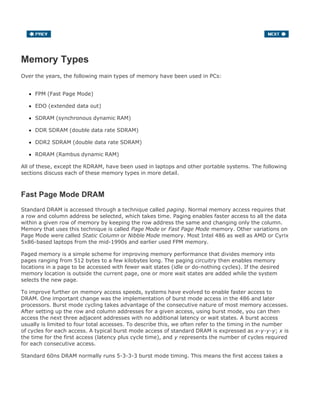
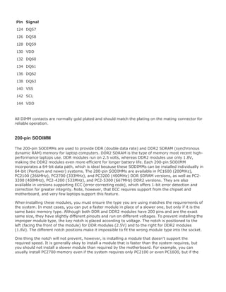
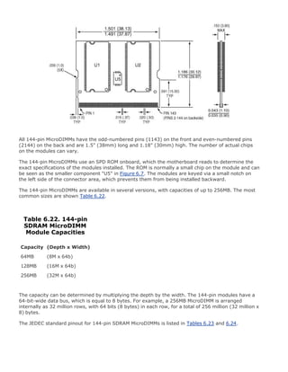
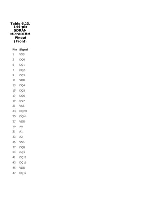
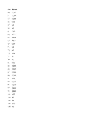
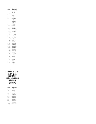
![The 144-pin SDRAM MicroDIMMs are only 1.5" (38mm) long and 1.18" (30mm) high, which is about
half the size of an equivalent SODIMM. Unlike SODIMMs, MicroDIMMs do not have any notches in the
connector pin area; however, a notch is used on the left side to ensure proper insertion. They also
have a unique size that is not interchangeable with other modules.
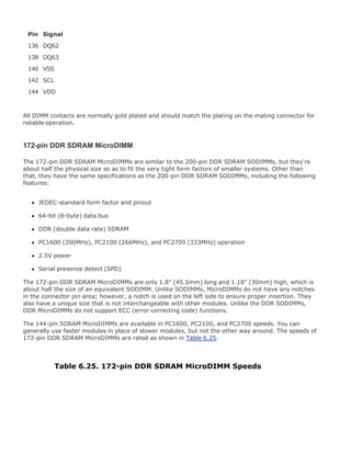
The 144-pin SDRAM MicroDIMMs are available in PC100 and PC133 speeds. You can generally use
PC133 modules in place of PC100 modules, but not the other way around. The speeds of 144-pin
MicroDIMMs are rated as shown in Table 6.21.
Table 6.21. 144-pin SDRAM MicroDIMM Speeds
Module Type Cycle Time
Module
Frequency Module Width
Module
Bandwidth
PC100 8.0ns 100MHz 8 bytes 800MBps
PC133 7.5ns 133MHz 8 bytes 1,066MBps
The throughput or bandwidth is simply the frequency times the width, which gives the rate at which
data can be read from or written to the module.
As with SDRAM SODIMMs, another performance specification to consider that is related to speed is
the CAS (column address strobe) Latency, often abbreviated as CL. Typically, you find SDRAM
modules rated CL 2 or CL 3. If possible, choose modules with a lower CL figure, because the
motherboard chipset will read that specification out of the SPD ROM on the module and switch to
slightly faster cycling rates.
The 144-pin SDRAM MicroDIMMs have the industry-standard form factor shown in Figure 6.7.
Figure 6.7. 144-pin SDRAM MicroDIMM.
[View full size image]](https://image.slidesharecdn.com/upgrading1-140602222156-phpapp02/85/Upgrading-1-laptop-2-th-364-320.jpg)

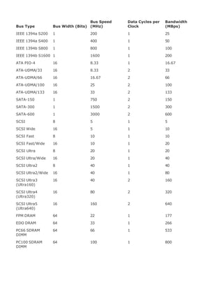
![Module Type Cycle Time
Frequency
SDR/DDR Module Width
Module
Bandwidth
PC2700 6.0ns 166/333MHz 8 bytes 2,666MBps
PC2100 7.5ns 133/266MHz 8 bytes 2,133MBps
PC1600 10.0ns 100/200MHz 8 bytes 1,600MBps
The cycle time in nanoseconds (billionths of a second) matches the single data rate (SDR) clock
speed, but double data rate (DDR) modules transfer twice per cycle, so the DDR frequency is always
double the SDR frequency. The throughput or bandwidth is simply the DDR frequency times the
width, which gives the rate at which data can be read from or written to the module.
As with DDR SDRAM SODIMMs, another performance specification to consider that is related to speed
is the CAS (column address strobe) Latency, often abbreviated as CL. Typically, you find SDRAM
modules rated CL 2 or CL 2.5. If possible, choose modules with a lower CL figure, because the
motherboard chipset will read that specification out of the SPD ROM on the module and switch to
slightly faster cycling rates.
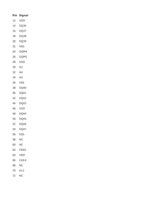
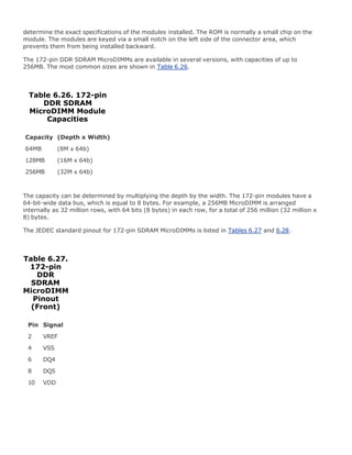
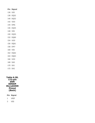
The 172-pin SDRAM MicroDIMMs have the industry-standard form factor shown in Figure 6.8.
Figure 6.8. 172-pin DDR SDRAM MicroDIMM.
[View full size image]
All 172-pin DDR SDRAM MicroDIMMs have the odd-numbered pins (1171) on the front and even-
numbered pins (2172) on the back and are 1.8" (45.5mm) long and 1.18" (30mm) high. The number
of actual chips on the modules can vary.
The 172-pin DDR SDRAM MicroDIMMs use an SPD ROM onboard, which the motherboard reads to](https://image.slidesharecdn.com/upgrading1-140602222156-phpapp02/85/Upgrading-1-laptop-2-th-372-320.jpg)

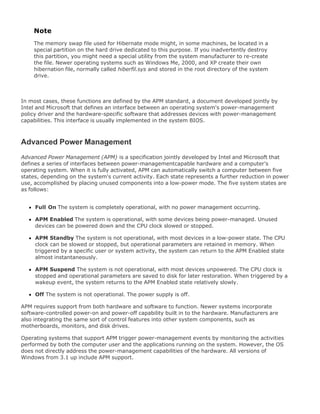
![HDD Power Down After the selected period of drive inactivity, any system IDE
devices compatible with the ATA-2 specification or later power-
manage themselves, putting themselves into an idle state after
the specified timeout and then waking themselves up when
accessed.
Throttle Duty Cycle When the system enters Doze mode, the CPU clock runs only
part of the time. You can select the percentage of time the
clock runs.
VGA Active Monitor When this setting is enabled, any video activity restarts the
global timer for Standby mode.
Soft Off by PWR-BTTN When you select Instant Off or Delay 4 Sec., turning off the
system with the On/Off button places the system in a very low
power-usage state, either immediately or after 4 seconds, with
only enough circuitry receiving power to detect power button
activity or Resume by Ring activity.
CPUFAN Off in Suspend When this setting is enabled, the CPU fan turns off during
Suspend mode.
Resume by Ring When this setting is enabled, an input signal on the serial Ring
Indicator (RI) line (in other words, an incoming call on the
modem) awakens the system from a soft off state.
Resume by Alarm When this setting is enabled, you can set the date and time at
which the real-time clock (RTC) alarm awakens the system
from Suspend mode.
Date (of Month) Alarm Select a date in the month when you want the alarm to go off.
Time (hh:mm:ss) Alarm Set the time you want the alarm to go off.
Wake Up On LAN When this setting is enabled, an input signal from a local area
network (LAN) awakens the system from a soft off state.
IRQ8 Break [Event From] You can select Enabled or SuspendDisabled for monitoring of
IRQ8 (the real-time clock) so that it does not awaken the
system from Suspend mode.
Reload Global Timer
Events
When this setting is enabled, an event occurring on eachdevice
listed restarts the global timer for Standby mode:
IRQ3-7, 9-15, NMI Secondary IDE 1
Primary IDE 0 Floppy Disk
Primary IDE 1 Serial Port
Secondary IDE 0 Parallel Port
Using the power-management settings in the BIOS Setup is especially helpful if you are using an
older operating system or one that is not ACPI aware, such as Windows 95, DOS, or Linux. If you are
using an ACPI-aware operating system such as Windows 98/Me, 2000, or XP, it is better to control](https://image.slidesharecdn.com/upgrading1-140602222156-phpapp02/85/Upgrading-1-laptop-2-th-410-320.jpg)

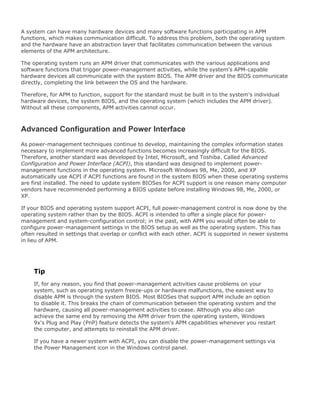
![might contain a connector for a cable leading to a telephone line, a network, or some other external
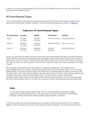
device. Type I, Type II, and Type III PC Cards are compared to each other in Figure 8.1.
Figure 8.1. PC Card Physical Types. One or two Type I or Type II PC
Cards (upper center) can be inserted into most notebook computers
(center), but only one Type III PC Card (upper right) can be used at a
time (lower center).
[View full size image]
The pinouts for the PC Card interfaces are shown in Table 8.4.](https://image.slidesharecdn.com/upgrading1-140602222156-phpapp02/85/Upgrading-1-laptop-2-th-418-320.jpg)

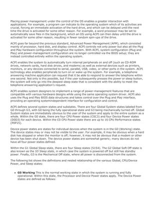
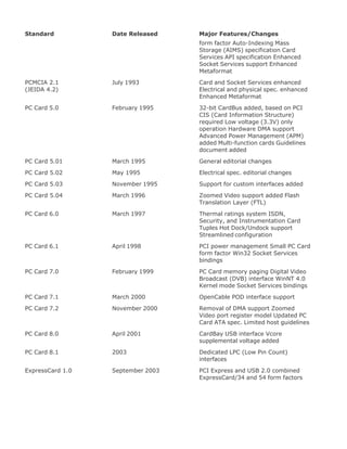
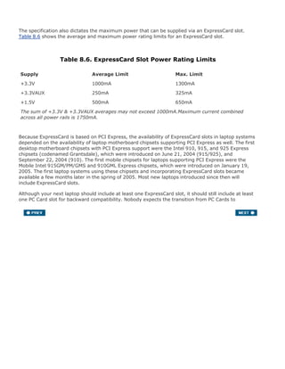
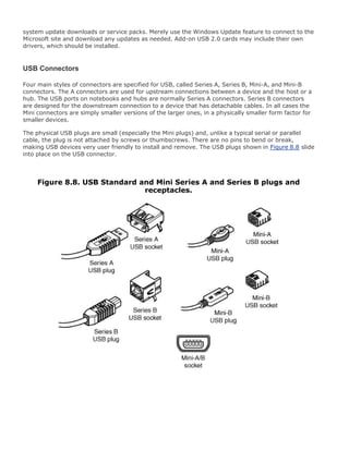
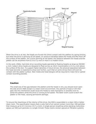
![ExpressCards
The original PCMCIA PC Card standards have been in use for over 15 years now and through
enhancements have evolved from about 20MBps to 133MBps in throughput. Unfortunately, the PC
Card specification has evolved to the point where further improvements in performance and
functionality are almost impossible.
Recognizing that a new type of small expansion card standard was needed for modern laptops and
other portable computing devices, on February 19, 2003, the PCMCIA announced that it was
developing a new interface card specification, codenamed NEWCARD, that was designed to replace
existing PC Cards for portable systems.
On September 16, 2003, the ExpressCard 1.0 interface standard was officially announced by the
PCMCIA at the Fall Intel Developer's Forum. After several years of chipset and motherboard
development, laptops with ExpressCard slots finally began appearing on the market in April 2005,
along with a variety of ExpressCard devices, such as Gigabit Ethernet, Bluetooth, and others (see
Figure 8.3). As systems with ExpressCard slots become predominant, the number of ExpressCards on
the market will also increase.
Figure 8.3. PCI Express for Laptops: ExpressCard/34 and
ExpressCard/54 cards.
[View full size image]](https://image.slidesharecdn.com/upgrading1-140602222156-phpapp02/85/Upgrading-1-laptop-2-th-425-320.jpg)
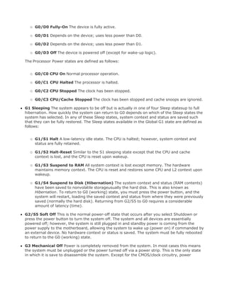
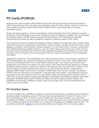
![motherboard chipset, requiring fewer components, fewer pins and signals, and lower cost
connectors.
Power ExpressCards require less power than current PC Cards and generate less heat. While it
doesn't save enough to be billed as a feature, it does offer a minor, but measurable,
improvement in battery life when these cards are installed (as compared to PC Cards).
Ease of use ExpressCards use existing operating systems and drivers, allowing for easy
installation and configuration.
ExpressCards will be available in two sizes: ExpressCard/34 (34mm wide) and ExpressCard/54
(54mm wide). Both feature a standard 75mm length and a thickness of 5mm. They are differentiated
only by the overall width and shape of the card. Figure 8.4 shows a comparison between the
dimensions of a CardBus PC Card, ExpressCard/54, and ExpressCard/34.
Figure 8.4. Relative size comparison between a CardBus PC Card, an
ExpressCard/54, and an ExpressCard/34.
[View full size image]
ExpressCard slots are also available in two sizes: 34mm wide and 54mm wide. The 34mm wide slots
support only ExpressCard/34 modules, while 54mm wide slots support either type of module. Most
laptops will have one or two 54mm wide slots, allowing use of either size card. Figure 8.5 shows how
ExpressCard/54 or ExpressCard/34 cards can fit into a 54mm slot.](https://image.slidesharecdn.com/upgrading1-140602222156-phpapp02/85/Upgrading-1-laptop-2-th-427-320.jpg)
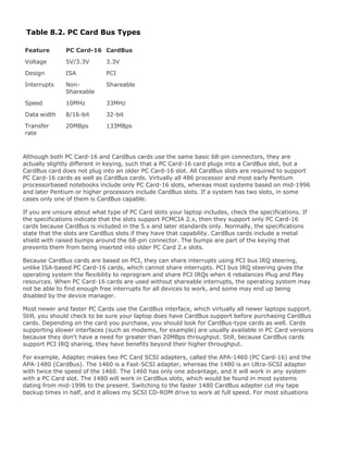
![Figure 8.5. A single 54mm wide ExpressCard slot can accommodate
either an ExpressCard/54 or ExpressCard/34 module.
[View full size image]
Because ExpressCard is based on existing PCI Express and USB serial interfaces, the ExpressCard
interface contains only 26 pins and is much simpler than the older 68-pin CardBus interface, which
was based on the parallel PCI bus. In addition to being simpler in design and componentry,
ExpressCard is also less costly since CardBus normally requires an extra CardBus controller chip to
act as an interface between PCI and CardBus, while ExpressCard merely uses the existing native PCI
Express and USB 2.0 interfaces, which are already built in to the motherboard chipset. This allows
ExpressCard support to be easily implemented in desktop systems as well.
Unlike PC Cards, ExpressCards don't require a complicated mechanical card ejection mechanism.
Instead, to further reduce costs, ExpressCards are designed with a simple finger grip ridge on the
outside edge, while the slot has a recessed area to allow you to easily grab the card and pull it out.
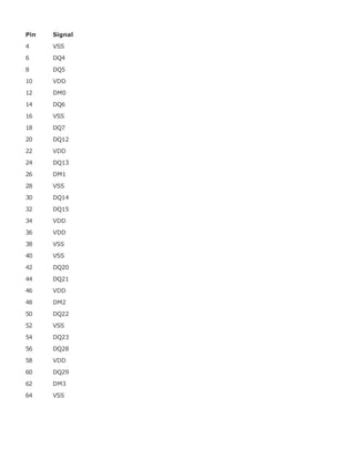
The pinout for the ExpressCard interface is shown in Table 8.5.
Table 8.5. ExpressCard Pinout
Pin Signal Description
1 GROUND Return current path
2 USBD- USB data interface
3 USBD+ USB data interface
4 CPUSB# USB presence detect
5 RESERVED -
6 RESERVED -
7 RESERVED -
8 SMB_CLK System Management Bus
9 SMB_DATA System Management Bus
10 +1.5V Secondary voltage source](https://image.slidesharecdn.com/upgrading1-140602222156-phpapp02/85/Upgrading-1-laptop-2-th-428-320.jpg)
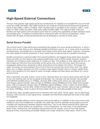
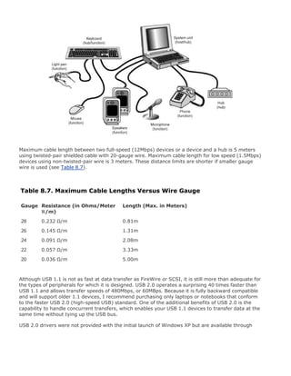
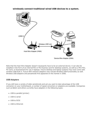
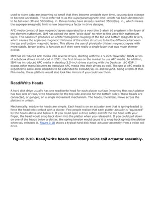
![Besides providing additional sockets for connecting USB peripherals, a hub can provide power to any
attached peripherals. A hub recognizes the dynamic attachment of a peripheral and provides at least
0.5W of power per peripheral during initialization. Under control of the host driver software, the hub
can provide more device power, up to a maximum of 2.5W, for peripheral operation.
Tip
For the most reliable operation, I recommend that you use self-powered hubs, which plug
into an AC adapter. Bus-powered hubs pull power from the PC's USB root hub connector
and aren't always capable of providing adequate power for power-hungry devices, such as
optical mice.
A newly attached hub is assigned a unique address, and hubs can be cascaded up to five levels deep
(see Figure 8.7). A hub operates as a bidirectional repeater and repeats USB signals as required both
upstream (toward the PC) and downstream (toward the device). A hub also monitors these signals
and handles transactions addressed to itself. All other transactions are repeated to attached devices.
A USB 1.1 hub supports both 12Mbps (full-speed) and 1.5Mbps (low-speed) peripherals.
Figure 8.7. A typical laptop with USB devices can use multiple USB hubs
to support a variety of peripherals, connected to whichever hub is most
convenient.
[View full size image]](https://image.slidesharecdn.com/upgrading1-140602222156-phpapp02/85/Upgrading-1-laptop-2-th-434-320.jpg)
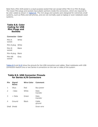
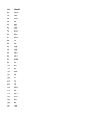
![Table 8.10. USB Connector Pinouts for
Mini-A/B Connectors
Pin Signal Name Wire Color Comment
1 Vbus Red Bus power
2 - Data White Data transfer
3 + Data Green Data transfer
4 ID A/B
identification[*]
5 Ground Black Cable ground
Shell Shield Drain wire
[*] Used to identify a Mini-A from a Mini-B connector to the device. ID is connected to Ground in a Mini-A plug and is not
connected (open) in a Mini-B plug.
USB conforms to Intel's PnP specification, including hot-plugging, which means that devices can be
plugged in dynamically without powering down or rebooting the system. Simply plug in the device,
and the USB controller in the PC detects the device and automatically determines and allocates the
required resources and drivers. To prevent data loss with USB drives and storage devices, when
disconnecting them via hot-plugging, you need to use the Eject Hardware or Safely Remove
Hardware feature in the Windows system tray. Click the device, select Stop, click OK, and wait for the
system to indicate that the device has been stopped before you remove it.
Microsoft has developed USB drivers and included them automatically in Windows 98 and later.
Windows 95B and 95C have very limited support for USB 1.1; the necessary drivers are not present
in the original Windows 95 or 95A. With Windows 95B, the USB drivers are not automatically
included; they are provided separately, although a late release of Windows 95Windows 95Cincludes
USB support. Many USB devices will not work with any Windows 95 releases, including those that
supposedly have the USB support files included.
Windows 98 and later include USB 1.1 support built in; however, additional drivers are required for
high-speed USB 2.0 or later. In most cases these drivers can be downloaded from Microsoft using the
Windows Update feature.
USB support is also required in the BIOS for devices such as keyboards and mice. This is included in
all newer systems with USB ports built in. Aftermarket PC Cards also are available for adding USB to
laptops and notebooks that don't include it as standard. USB peripherals include printers, optical
drives, modems, scanners, telephones, joysticks, keyboards, and pointing devices such as mice and
trackballs.
A free utility called USBready is available from the www.usb.org site that examines your system's
hardware and software and informs you of your system's USB capabilities. Most laptop systems built
in 1997 or earlier don't support USB. During 1998, most laptops began supporting USB, and if your
system dates from 1999 or later, built-in USB support is almost a certainty. One interesting feature
of USB is that with certain limitations, attached devices can be powered by the USB bus. The PnP](https://image.slidesharecdn.com/upgrading1-140602222156-phpapp02/85/Upgrading-1-laptop-2-th-438-320.jpg)
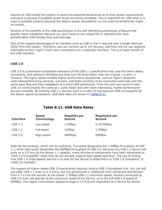
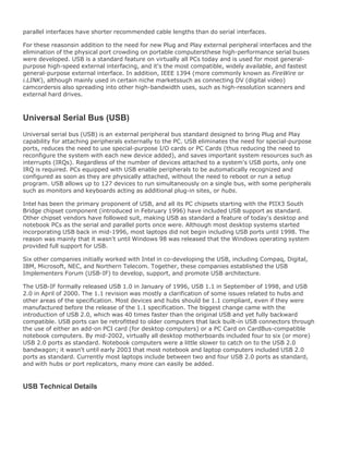
![IEEE 1394a[1] IEEE 1394b[2] USB 1.1 USB 2.0
PC host required No No Yes Yes/No[3]
Maximum number
of devices
63 63 127 127
Hot-swappable Yes Yes Yes Yes
Maximum cable
length between
devices
4.5 meters 4.5 meters[4] 5 meters 5 meters
Transfer rate 400Mbps
(50MBps)
800Mbps
(100MBps)
12Mbps (1.5MBps) 480Mbps
(60MBps)
Typical devices DV camcorders;
digital cameras;
HDTV; set-top
boxes; hard disk
drives; scanners;
musical
instruments
All 1394a devices Keyboards; mice;
joysticks; digital
cameras; hard
disk drives;
modems; printers;
scanners
All USB 1.1
devices; DV
camcorders;
HDTV; set-top
boxes; musical
instruments
[1] IEEE 1394a is also called FireWire 400 or i.LINK.
[2] IEEE 1394b is also called FireWire 800.
[3] No with USB On-The-Go.
[4] 9-pin copper; 100 meters with fiber optic.
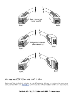
Because the overall performance and physical specifications are similar, the main difference between
USB and 1394 would be popularity. The bottom line is that USB is by far the most popular external
interface for PCs, eclipsing all others by comparison. The reason primarily is that Intel developed
most of USB and has placed built-in USB support in all its motherboard chipsets since 1996. There
are virtually no motherboard chipsets that integrate 1394; in most cases it has to be added as an
extra-cost chip to the motherboard. The cost of the additional 1394 circuitry, the Apple royalties, and
the fact that all motherboards already have USB have conspired to greatly limit the popularity of
1394 (FireWire) in the notebook PC marketplace.
Many people like to bring any comparison of USB and 1394 down to speed, but that is a constantly
changing parameter. 1394a offers a data transfer rate more than 33 times faster than that of USB
1.1, but is only about 83% as fast as USB 2.0. However, 1394b is about 66% faster than USB 2.0.
Because both USB 2.0 and 1394a (FireWire) offer relatively close to the same overall capabilities and
performance, you make your choice based on which devices you intend to connect. If the digital
video camera you want to connect has only a 1394 (FireWire/i.LINK) connection, you will need to add
a 1394 FireWire card to your system, if such a connection isn't already present on your motherboard.
Most general-purpose PC storage, I/O, and other devices are USB, whereas only video devices
usually have 1394 connections. However, many devices now offer both USB 2.0 and 1394 interfaces
to enable use with the widest range of computers.](https://image.slidesharecdn.com/upgrading1-140602222156-phpapp02/85/Upgrading-1-laptop-2-th-450-320.jpg)
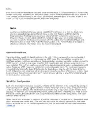
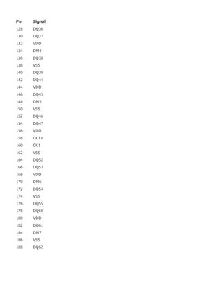
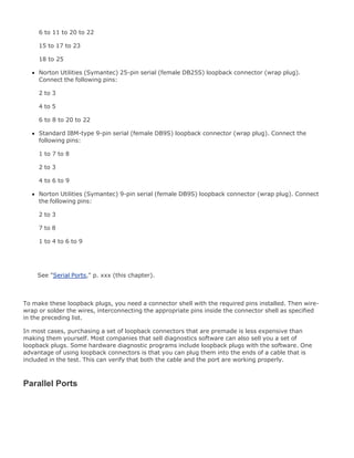
![Table 8.16. Standard
Serial I/O Port
Addresses and
Interrupts
COM I/O
Ports
IRQ
COM1 3F8-
3FFh
IRQ4
COM2 2F8-
2FFh
IRQ3
COM3 3E8-
3EFh
IRQ4[*]
COM4 2E8-
2EFh
IRQ3[*]
[*] Note that although many serial ports can be set up to share IRQ3 and IRQ4 with COM1 and COM2, this is not recommended.
The best recommendation is setting COM3 to IRQ10 and COM4 to IRQ11 (if available).
If you are adding more than the standard COM1 and COM2 serial ports, be sure they use unique and
nonconflicting interrupts. If you purchase a serial port adapter card and intend to use it to supply
ports beyond the standard COM1 and COM2, be sure it can use interrupts other than IRQ3 and IRQ4;
the latest CardBus-based serial port cards take advantage of IRQ-sharing features to allow COM3 and
above to use a single IRQ without conflicts.
Note that BIOS manufacturers never built support for COM3 and COM4 into the BIOS. Therefore,
DOS cannot work with serial ports above COM2 because DOS gets its I/O information from the BIOS.
The BIOS finds out what is installed in your system, and where it is installed, during the Power On
Self Test (POST). The POST checks only for the first two installed ports. This is not a problem under
Windows because Windows 95 and later have built-in support for up to 128 ports.
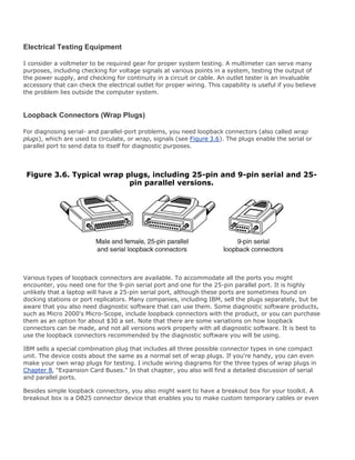
Testing Serial Ports
You can perform several tests on serial and parallel ports. The two most common types of tests are
those that involve software only and those that involve both hardware and software. The software-
only tests are done with diagnostic programs, such as Microsoft's MSD or the modem diagnostics built
in to Windows, whereas the hardware and software tests involve using a wrap plug to perform
loopback testing.
See "Testing Parallel Ports," p. 331.
See "Advanced Diagnostics Using Loopback Testing," p. 322.](https://image.slidesharecdn.com/upgrading1-140602222156-phpapp02/85/Upgrading-1-laptop-2-th-457-320.jpg)
![Microsoft Diagnostics
Microsoft Diagnostics (MSD) is a diagnostic program supplied with MS-DOS 6.x, Windows 3.x, and
Windows 9x/Me/2000. Note that with Windows 95, this program can be found on the CD-ROM in the
othermsd directory. In Windows 98/Me/2000, you can find it on the CD-ROM in thetoolsoldmsdos
directory. MSD is not automatically installed when you install the operating system. To use it, you
must run it from the CD-ROM directly or copy the program from the CD-ROM to your hard disk.
For the most accurate results, many diagnostics programs, such as MSD, are best run in a DOS-only
environment. Because of this, you need to restart the machine in DOS mode before using them.
Then, to use MSD, switch to the directory in which it is located. This is not necessary, of course, if the
directory that contains the program is in your search pathwhich is often the case with the DOS 6.x or
Windows-provided versions of MSD. Then, simply type MSD at the DOS prompt and press Enter.
Soon you see the MSD screen.
Select the Serial Ports option. Notice that you are given information about which type of serial chip
you have in your system, as well as information about which ports are available. If any of the ports
are in use (with a mouse, for example), that information is provided as well. MSD is helpful in at least
determining whether your serial ports are responding. If MSD cannot determine the existence of a
port, it does not provide the report which indicates that the port exists. This sort of "look-and-see"
test is the first action I usually take to determine why a port is not responding.
Troubleshooting Ports in Windows
Windows 9x/Me can tell you whether your ports are functioning. First, you must verify that the
required communications files are present to support the serial ports in your system:
Verify the file sizes and dates of both COMM.DRV (16-bit serial driver) and SERIAL.VXD (32-bit
serial driver) in the SYSTEM directory, compared to the original versions of these files from the
Windows 9x/Me CD-ROM.
1.
Confirm that the following lines are present in SYSTEM.INI:
[boot]
comm.drv=comm.drv
[386enh]
device=*vcd
2.
The SERIAL.VXD driver is not loaded in SYSTEM.INI; instead, it is loaded through the Registry.
Windows 2000 and XP use the SERIAL.SYS and SERENUM.SYS drivers for handling RS-232 devices. You
can compare the file sizes and dates for these files to those on the Windows 2000 CD-ROM. If both
drivers are present and accounted for, you can determine whether a particular serial port's I/O
address and IRQ settings are properly defined by following these steps for Windows 9x/Me/2000:](https://image.slidesharecdn.com/upgrading1-140602222156-phpapp02/85/Upgrading-1-laptop-2-th-458-320.jpg)
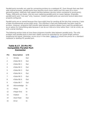
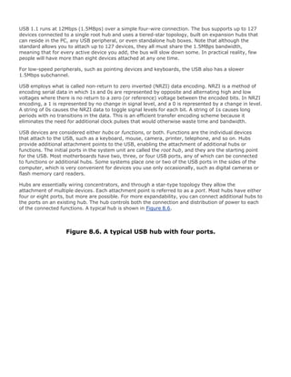
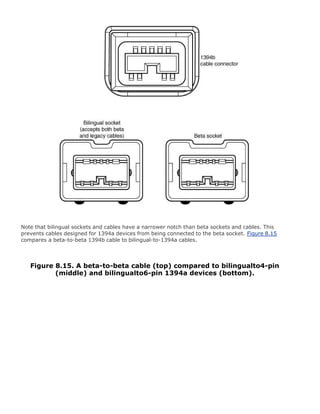
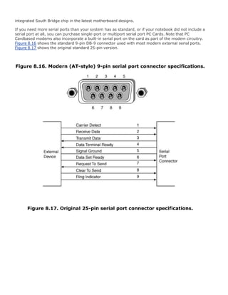
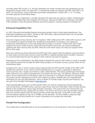
![printer cable is no longer the standard printer cable. The IEEE 1284 printer cable uses twisted-pair
technology, which results in a much more reliable and error-free connection.
The IEEE 1284 standard also defines the parallel port connectors, including the two preexisting types
(Type A and Type B), as well as an additional high-density Type C connector. Type A refers to the
standard DB25 connector used on most PC systems for parallel port connections, whereas Type B
refers to the standard 36-pin Centronics-style connector found on most printers. Type C is a more
recent high-density 36-pin connector that can be found on some printers on the market, such as
those from HP. The three connectors are shown in Figure 8.18.
Figure 8.18. The three different types of IEEE 1284 parallel port
connectors.
[View full size image]
Most parallel ports use the standard Type A receptacle, as shown in Figure 8.19.
Figure 8.19. Standard Type A parallel port connector.](https://image.slidesharecdn.com/upgrading1-140602222156-phpapp02/85/Upgrading-1-laptop-2-th-463-320.jpg)
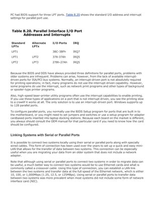
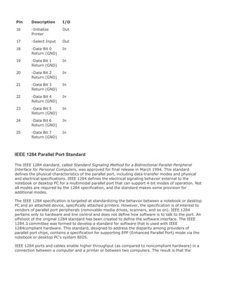
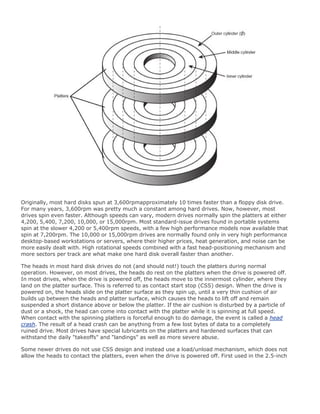
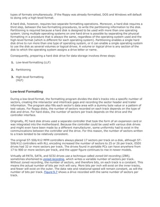
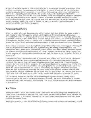
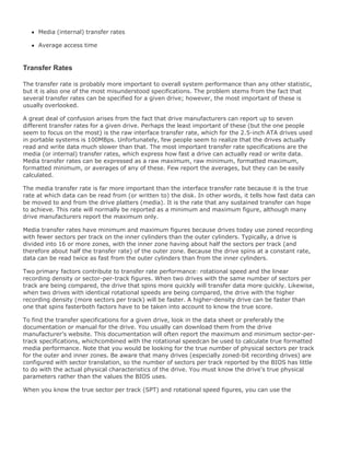
![Areal Density
Areal density is often used as a technology growth-rate indicator for the hard disk drive industry.
Areal density is defined as the product of the linear bits per inch (bpi), measured along the length of
the tracks around the disk, multiplied by the number of tracks per inch (tpi), measured radially on
the disk (see Figure 9.1). The results are expressed in units of megabits or gigabits per square inch
(Mbit/sq. in. or Gbit/sq. in.) and are used as a measure of efficiency in drive-recording technology.
Current high-end 2.5-inch drives record at areal densities over 100Gbit/sq. in. This density will allow
for 3.5-inch drives with capacities of 1000GB or 1TB in the next few years.
Figure 9.1. Areal density, combining tracks per inch and bits per inch.
[View full size image]
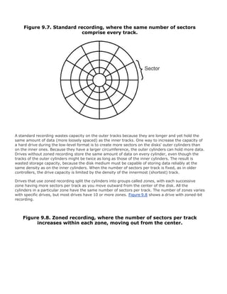
Drives record data in tracks, which are circular bands of data on the disk. Each track is divided into
sectors. Figure 9.2 shows an actual floppy disk sprayed with magnetic developer (powdered iron)
such that an image of the actual tracks and sectors can be clearly seen. The disk shown is a 5.25-
inch 360KB floppy, which has 40 tracks per side, and each track is divided into nine sectors. Note
that each sector is delineated by gaps in the recording, which precede and follow the track and sector
headers (where ID and address information resides). You can clearly see the triple gap preceding the
first sector, which includes the track and sector headers. Then, following in a counterclockwise
direction, you see each subsequent sector, preceded by gaps delineating the header for that sector.
Data is written in the area between the headers.
Figure 9.2. A 360KB floppy disk media sprayed with magnetic developer
(powdered iron) showing the actual track and sector images.
[View full size image]](https://image.slidesharecdn.com/upgrading1-140602222156-phpapp02/85/Upgrading-1-laptop-2-th-474-320.jpg)
![Several drive manufacturers have already announced 2.5- and 3.5-inch drives based on this
technology. This technology will see its debut in 2.5-inch drives for laptops and 1-inch drives for
portable electronics, such as digital cameras and PDAs first, before finding its way into 3.5-inch drives
for desktop PCs and servers.
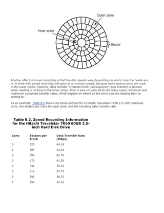
Figure 9.3 shows how areal density has increased from when magnetic storage was first developed
(1956 RAMAC) through the present time.
Figure 9.3. Evolution of areal density in magnetic disk storage.
[View full size image]
To increase areal density while maintaining the same external drive form factors, drive
manufacturers have developed media and head technologies to support these higher areal densities,
such as ceramic/glass platters, giant magneto-resistive (GMR) heads, pseudo-contact recording, and
partial response maximum likelihood (PRML) electronics. The primary challenge in achieving higher
densities is manufacturing drive heads and disks to operate at closer tolerances. Improvements in
tolerances and the use of more platters in a given form factor continue to fuel improvements in drive
capacity, but drive makers continue to seek even greater capacity increases, both by improving
current technologies and by developing new ones.
To fit more data on a platter of a given size, the tracks must be placed closer together, and the
heads must be capable of achieving greater precision in their placements over the tracks. This also
means that as hard disk capacities increase, heads must float ever closer to the disk surface during
operation. The gap between the head and disk is as close as 10 nanometers (0.01 microns) in some
drives, which is approximately the thickness of a cell membrane. By comparison, a human hair is](https://image.slidesharecdn.com/upgrading1-140602222156-phpapp02/85/Upgrading-1-laptop-2-th-476-320.jpg)

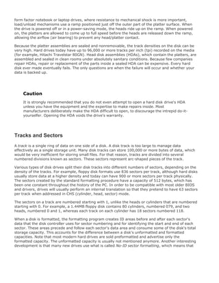
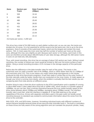
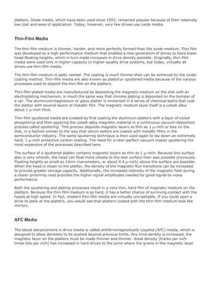
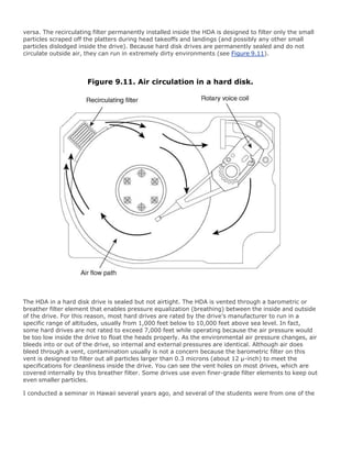
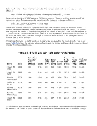
![Hard Disk Drive Operation
The basic physical construction of a hard disk drive consists of spinning disks with heads that move
over the disks and store data in tracks and sectors. The heads read and write data in concentric rings
called tracks. These tracks are divided into segments called sectors, which normally store 512 bytes
each (see Figure 9.5).
Figure 9.5. The tracks and sectors on a disk.
[View full size image]
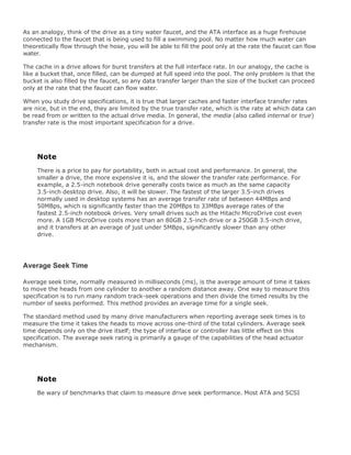
Hard disk drives usually have multiple disks, called platters, that are stacked on top of each other
and spin in unison, each with two sides on which the drive stores data. Most drives have one, two, or
three platters, resulting in two, four, or six sides. The identically aligned tracks on each side of every
platter together make up a cylinder (see Figure 9.6). A hard disk drive normally has one head per
platter side, with all the heads mounted on a common carrier device or rack. The heads move radially
across the disk in unison; they cannot move independently because they are mounted on the same
carrier or rack, called an actuator.
Figure 9.6. Hard disk cylinders.
[View full size image]](https://image.slidesharecdn.com/upgrading1-140602222156-phpapp02/85/Upgrading-1-laptop-2-th-484-320.jpg)
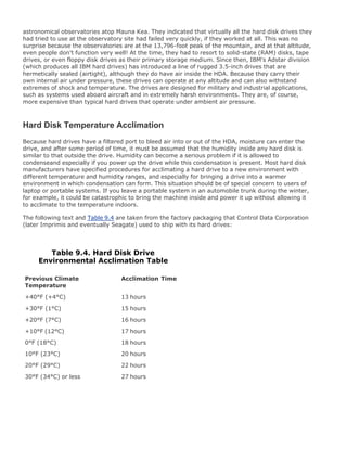
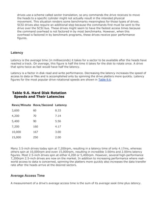
![Basic Hard Disk Drive Components
Many types of hard disk drives are on the market, but nearly all share the same basic physical
components. Some differences might exist in the quality of these components (and in the quality of
the materials used to make them), but the operational characteristics of most drives are similar. The
basic components of a typical hard disk drive are as follows:
Disk platters
Read/write heads
Head actuator mechanism
Spindle motor (inside platter hub)
Logic board (controller or printed circuit board)
Cables and connectors
Configuration items (such as jumpers or switches)
You can see each of these components in Figure 9.9.
Figure 9.9. Typical hard disk drive components.
[View full size image]](https://image.slidesharecdn.com/upgrading1-140602222156-phpapp02/85/Upgrading-1-laptop-2-th-494-320.jpg)
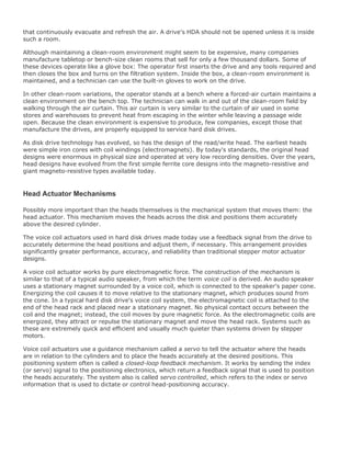
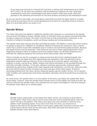


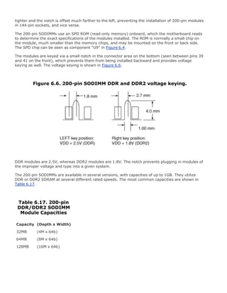
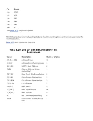
![Table 9.7. ATA Standards
Standard Timeframe PIO
DMA
Modes
UDMA
Modes Speed[1]Modes Features
ATA-1 19861994 02 0 8.33 Drives support up to 136.9GB.
BIOS issues not addressed.
ATA-2 19951996 04 02 16.67 Faster PIO modes. CHS/LBA
BIOS translation defined up to
8.4GB. PC Card.
ATA-3 19961997 04 02 16.67 SMART. Improved signal
integrity.
LBA support mandatory.
Eliminated single-word DMA
modes.
ATA-4 19971998 04 02 02 33.33 Ultra-DMA modes. BIOS
support up to 136.9GB.
ATA-5 19982000 04 02 04 66.67 Faster UDMA modes. 80-pin
cable with auto-detection.
ATA-6 20002002 04 02 05 100.00 100MBps UDMA mode.
Extended drive and BIOS
support up to 144PB.
ATA-7 2002present 0-4 02 06 133.00 133MBps UDMA mode.
SMART = Self-Monitoring Analysis and Reporting Technology
MB = megabyte (million bytes)
GB = gigabyte (billion bytes)
PB = petabyte (quadrillion bytes)
CHS = cylinder, head, sector
LBA = logical block address
PIO = programmed I/O
DMA = direct memory access
UDMA = Ultra-DMA (direct memory access)
[1] Speed is megabytes per second
ATA-1
Although ATA-1 had been used since 1986 before being published as a standard, and although it was](https://image.slidesharecdn.com/upgrading1-140602222156-phpapp02/85/Upgrading-1-laptop-2-th-521-320.jpg)
![ATA Features
The ATA standards have gone a long way toward eliminating incompatibilities and problems with
drive interfacing. The ATA specifications define the signals on the 40- or 44-pin connector, the
functions and timings of these signals, cable specifications, and so on. This section lists some of the
elements and functions defined by the ATA specification.
ATA I/O Connector
The ATA interface connector is normally a 40-pin (for 3.5-inch drives) or 44-pin (for 2.5-inch or
smaller drives) header-type connector with pins spaced 0.1 inches (2.54mm) apart and generally is
keyed to prevent installing it upside down (see Figures 9.12 and 9.13 ). To create a keyed connector,
the manufacturer generally removes pin 20 from the male connector and blocks pin 20 on the female
cable connector, which prevents the user from installing the cable backward. Some cables also
incorporate a protrusion on the top of the female cable connector that fits into a notch in the shroud
surrounding the mating male connector on the device. The use of keyed connectors and cables is
highly recommended; plugging in an ATA cable backward normally won't cause any permanent
damage. However, it can lock up the system and prevent it from running at all.
Figure 9.12. Typical ATA hard drive connectors.
[View full size image]](https://image.slidesharecdn.com/upgrading1-140602222156-phpapp02/85/Upgrading-1-laptop-2-th-527-320.jpg)
![Figure 9.13. ATA 40-pin interface connector detail.
[View full size image]
Table 9.8 shows the standard 40-pin ATA interface connector pinout.
-RESET
1](https://image.slidesharecdn.com/upgrading1-140602222156-phpapp02/85/Upgrading-1-laptop-2-th-528-320.jpg)

![16
Data Bit 14
Data Bit 0
17
18
Data Bit 15
GROUND
19
20
KEY (pin missing)
DRQ 3
21
22
GROUND
-IOW
23
24
GROUND
-IOR
25
26
GROUND
I/O CH RDY
27
28
CSEL:SPSYNC[1]
-DACK 3
29](https://image.slidesharecdn.com/upgrading1-140602222156-phpapp02/85/Upgrading-1-laptop-2-th-530-320.jpg)
![30
GROUND
IRQ 14
31
32
Reserved[2]
Address Bit 1
33
34
-PDIAG
Address Bit 0
35
36
Address Bit 2
-CS1FX
37
38
-CS3FX
-DA/SP
39
40
GROUND
+5V (Logic)
41
42
+5V (Motor)
GROUND
43](https://image.slidesharecdn.com/upgrading1-140602222156-phpapp02/85/Upgrading-1-laptop-2-th-531-320.jpg)
![44
Reserved
Note that "-" preceding a signal name (such as with -RESET) indicates the signal is "active low."
Table 9.8. 40-Pin ATA Connector
Signal Name Pin Pin Signal Name
[1] Pin 28 is normally cable select, but some older drives could use it for spindle synchronization between multiple drives.
[2] Pin 32 was defined as -IOCS16 in ATA-2 but is no longer used.
The 2.5-inch drives found in notebook/laptop-size computers normally use a smaller unitized 50-pin
header connector with pins spaced only 2.0mm (0.079 inches) apart.
The main 40-pin part of the connector is the same as the standard ATA connector (except for the
physical pin spacing), but there are added pins for power and jumpers. Normally, the cable that plugs
into this connector has 44 pins, carrying power as well as the standard ATA signals. The jumper pins
normally have a jumper on them (the jumper position controls cable select, master, or slave
settings). Figure 9.14 shows the unitized 50-pin connector used on 2.5-inch ATA drives normally
found in laptop or notebook computers.
Figure 9.14. 50-pin unitized ATA connector detail (used on 2.5-inch
notebook/laptop ATA drives with a 44-pin cable).
Note the jumper pins at positions AD and that the pins at positions E and F are removed. A jumper
usually is placed between positions B and D to set the drive for cable select operation. On this
connector, pin 41 provides +5V power to the drive logic (circuit board), pin 42 provides +5V power to
the motor (2.5-inch drives use 5V motors, unlike larger drives, which normally use 12V motors), and
pin 43 provides a power ground. The last pin (44) is reserved and not used.
Table 9.9 shows the 50-pin unitized ATA interface connector pinout as used on most 2.5-inch (laptop
or notebook computer) drives.](https://image.slidesharecdn.com/upgrading1-140602222156-phpapp02/85/Upgrading-1-laptop-2-th-532-320.jpg)

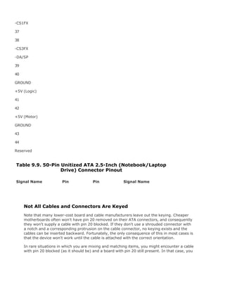
![can break off pin 20 from the board, or for the more squeamish, remove the block from the
cable. Some cables have the block permanently installed as a part of the connector
housing, in which case you must break off pin 20 on the board or device end or use a
different cable.
The simple rule of thumb is that pin 1 should be oriented toward the power connector on
the device, which normally corresponds to the stripe on the cable.
ATA I/O Cable
A 40-conductor ribbon cable is specified to carry signals between the bus adapter circuits and the
drive (controller). To maximize signal integrity and eliminate potential timing and noise problems, the
cable should not be longer than 18 inches (0.46 meters).
Note that ATA drives supporting the higher-speed transfer modes, such as PIO Mode 4 or any of the
Ultra-DMA (UDMA) modes, are especially susceptible to cable integrity problems and cables that are
too long. If the cable is too long, you can experience data corruption and other errors that can be
maddening. This will be manifested in any type of problem reading from or writing to the drive. In
addition, any drive using UDMA Mode 4 (66MBps transfer rate), Mode 5 (100MBps transfer rate), or
Mode 6 (133MBps transfer rate) must use a special higher-quality 80-conductor cable (the extra
conductors are grounds to reduce noise). I also recommend this type of cable if your drive is running
at UDMA Mode 2 (33MBps) or slower because it can't hurt and can only help. Although cable length is
not a problem inside portable systems, finding replacement cables that fit can be difficult. Many
portables use special cables, called flex-cables , that are constructed like a filmstrip with the "wires"
printed on much like on a circuit board. Because of their custom construction, you normally can't
replace the cables inside a laptop with different ones than supplied by the manufacturer. Figure 9.15
shows the typical desktop ATA cable layout and dimensions. Unlike standard ATA ribbon cables, which
allow for two drives to be connected, the flex-cables in a laptop will normally support only a single
drive at a time.
Figure 9.15. An ATA cable with 40-pin connectors and either 40- or 80-
conductor cables (additional wires are grounded in 80-conductor
versions).
[View full size image]](https://image.slidesharecdn.com/upgrading1-140602222156-phpapp02/85/Upgrading-1-laptop-2-th-537-320.jpg)
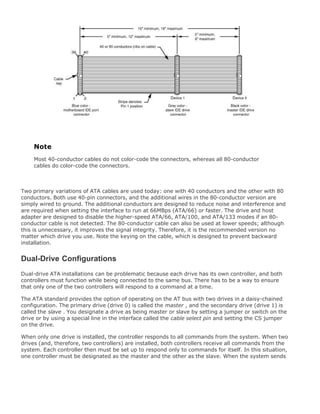
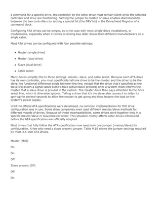
![Off
Cable select (CS)
Off
Off
Off
Table 9.10. Jumper Settings for Most 3.5-inch ATA Drives on
Standard (NonCable Select) Cables
Jumper Name Single-Drive Dual-Drive Master Dual-Drive Slave
Note
If a cable select cable is used, the CS jumper should be set to On and all others should be
Off. The cable connector then determines which drive will be master or slave.
Figure 9.16 shows the jumpers on a typical 3.5-inch ATA drive.
Figure 9.16. ATA drive jumpers for most 3.5-inch drives.
[View full size image]](https://image.slidesharecdn.com/upgrading1-140602222156-phpapp02/85/Upgrading-1-laptop-2-th-540-320.jpg)
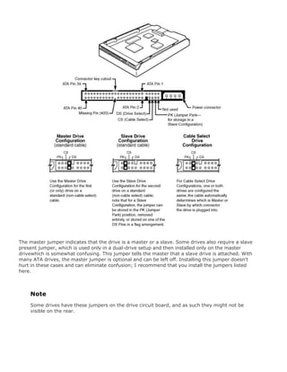
![The 2.5-inch drives used internally in most portables have a different jumper arrangement. The four
jumper pins, labeled A, B, C, and D, are shown in Figure 9.17 .
Figure 9.17. ATA drive jumpers for most 2.5-inch drives.
[View full size image]
Because most 2.5-inch drives are installed as the only drive on the cable, you normally don't install
any jumper, which results in a default master setting. Installing a jumper connecting the A-B pins
results in a slave setting, and jumpering B-D is for cable select. Other jumper settings are not used.
To eliminate confusion over master/slave settings, most newer systems with cables supporting dual
drives now use the cable select option. This involves two things. The first is having a special ATA
cable that has all the wires except pin 28 running from the motherboard connector to both drive
connectors. Pin 28 is used for cable select and is connected to one of the drive connectors (labeled
master) and not to the other (labeled slave). Both drives are then configured in cable select mode via
the CS jumper on each drive.
With cable select, the drive that receives signals on pin 28 automatically becomes the master, and
the other becomes the slave. Most cables implement this by removing the metal insulation
displacement bit from the pin-28 hole, which can be difficult to see at a glance. Other cables have a
section of pin 28 visibly cut from the cable somewhere along the ribbon. Because this is such a minor
modification to the cable and can be difficult to see, cable select cables normally have the connectors
labeled master, slave, and system, indicating that the cable controls these options rather than the
drive. All 80-conductor Ultra-ATA cables are designed to use cable select.
With cable select, you simply set the CS jumper on all drives and then plug the drive you want to be
the master into the connector labeled master on the cable and the drive you want to be the slave into
the connector labeled slave.
The only downside I see to using cable select is that it may restrict how the cable is routed or where
you mount the drive that is to be the master versus the slave, because they must be plugged into](https://image.slidesharecdn.com/upgrading1-140602222156-phpapp02/85/Upgrading-1-laptop-2-th-542-320.jpg)
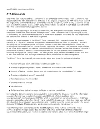
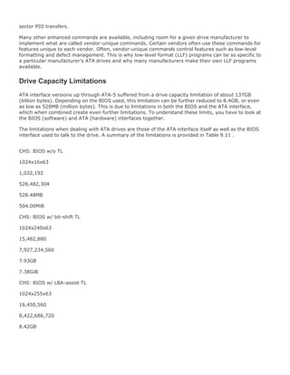
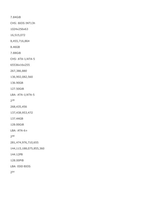
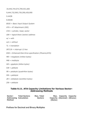
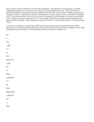

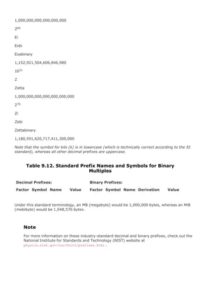
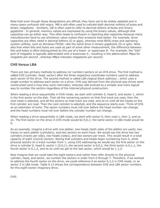
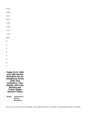

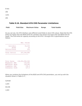
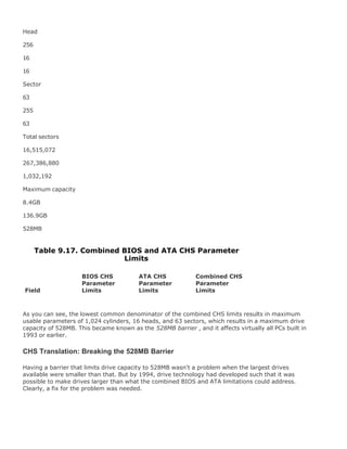
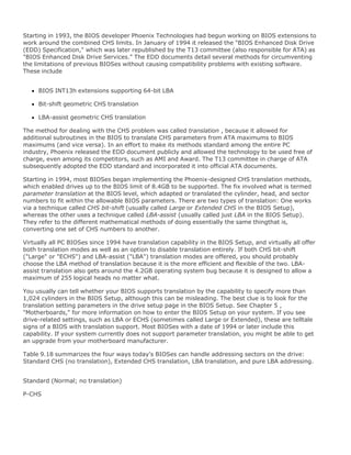
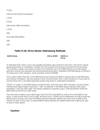
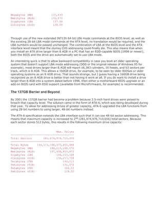
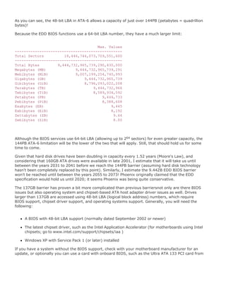
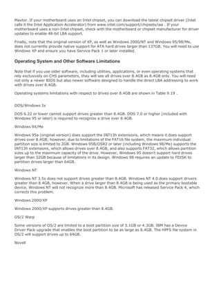
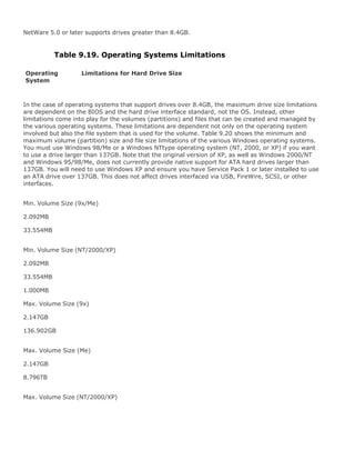
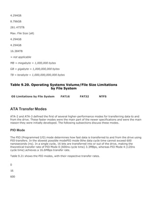

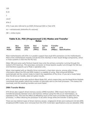
![modes are also sometimes called busmaster ATA modes because they use a host adapter that
supports busmastering. Ordinary DMA relies on the legacy DMA controller on the motherboard to
perform the complex task of arbitration, grabbing the system bus and transferring the data. In the
case of busmastering DMA, all this is done by a higher-speed logic chip in the host adapter interface
(which is also on the motherboard).
Systems using the Intel PIIX (PCI IDE ISA eXcelerator) or mobile PIIX and later South Bridge chips
(or equivalent) have the capability of supporting busmaster ATA. The singleword and doubleword
busmaster ATA modes and transfer rates are shown in Tables 9.22 and 9.23 .
0
16
960
1.04
1
2.08
ATA-1[1]
1
16
480
2.08
1
4.17
ATA-1[1]
2
16
240
4.17
1
8.33
ATA-1[1]
Table 9.22. Singleword (8-bit) DMA Modes and Transfer](https://image.slidesharecdn.com/upgrading1-140602222156-phpapp02/85/Upgrading-1-laptop-2-th-569-320.jpg)
![Rates
8-bit DMA
Mode
Bus
Width
(bits)
Cycle
Speed
(ns)
Bus
Speed
(MHz)
Cycles
per
Clock
Transfer
Rate
(MBps)
ATA
Specification
[1] Singleword (8-bit) DMA modes were removed from the ATA-3 and later specifications.
0
16
480
2.08
1
4.17
ATA-1
1
16
150
6.67
1
13.33
ATA-2
2
16
120
8.33
1
16.67
ATA-2
ATA-2 was also referred to as EIDE (Enhanced IDE) or Fast-ATA.](https://image.slidesharecdn.com/upgrading1-140602222156-phpapp02/85/Upgrading-1-laptop-2-th-570-320.jpg)
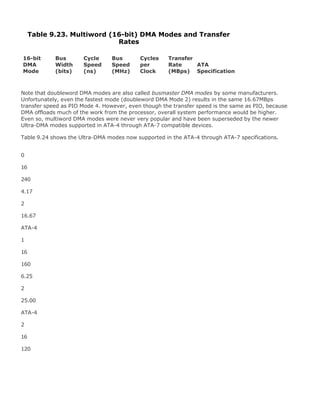

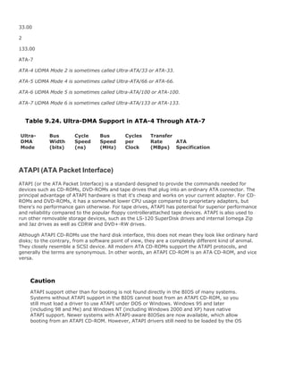

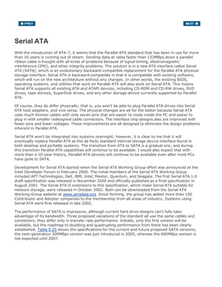
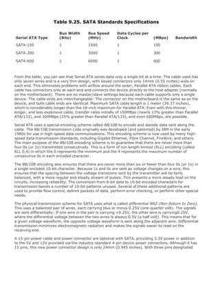
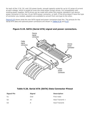
![The configuration of Serial ATA devices is also much simpler because the master/slave or cable select
jumper settings used with Parallel ATA are no longer necessary.
Serial ATA is ideal for laptop and notebook systems, and it will eventually replace Parallel ATA in
those systems as well. In late 2002, Fujitsu demonstrated a prototype 2.5-inch SATA drive. Most 2.5-
inch hard drive manufacturers were waiting for mobile chipsets supporting SATA to be delivered
before officially introducing mobile SATA drives. Both the chipsets and the drives began arriving in
2005, and by late 2005 the first laptops were available with SATA drives. Even if your laptop system
does not support SATA internally, you can add an SATA interface externally via a PC Card, such as
the Addonics CardBus Serial ATA adapter. This card adds two high-speed Serial ATA ports to any
laptop or notebook computer via a PC Card slot. This enables you to connect drives with 2.5 times
the data transfer rate of USB 2.0. The card plus an external cable sells for under $100.
Figure 9.20 shows the Addonics CardBus Serial ATA adapter.
Figure 9.20. Addonics CardBus Serial ATA adapter.
Although SATA is not normally designed to be used as an external interface, Addonics has available
external drive enclosures as well as a special cable that pulls power from a spare USB port. Using a
special cable that's provided, you can connect external hard drives or even CD-ROM/DVD drives via a
high-speed SATA connection. Figure 9.21 shows the special Addonics cable, which allows a variety of
external SATA devices to be connected to any portable system.
Figure 9.21. Addonics Serial ATA devices for Laptops.
[View full size image]](https://image.slidesharecdn.com/upgrading1-140602222156-phpapp02/85/Upgrading-1-laptop-2-th-579-320.jpg)
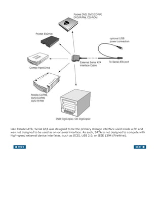
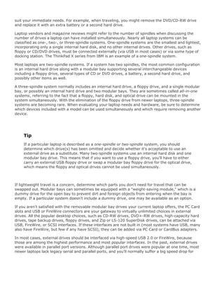
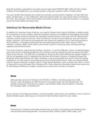
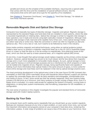
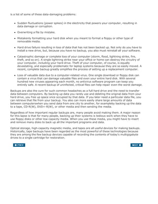
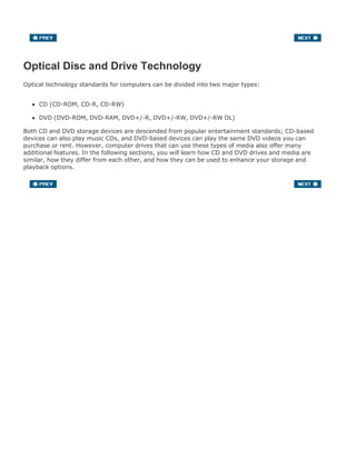
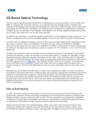
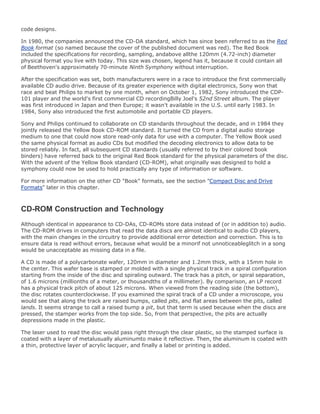
![Caution
CD-ROM media should be handled with the same care as a photographic negative. The CD-
ROM is an optical device and degrades as its optical surface becomes dirty or scratched.
Also, it is important to note that although discs are read from the bottom, the layer
containing the track is actually much closer to the top of the disc. The reason is that the
protective lacquer overcoat is only 6 to 7 microns (about one quarter of a thousandth of an
inch) thick. Writing on the top surface of a disc with a ballpoint pen, for example, will easily
damage the recording underneath. You need to be careful even when using a marker to
write on the disc. The inks and solvents used in some markers can damage the print and
lacquer overcoat on the top of the disc, and subsequently the information layer right below.
Use only markers designed for writing on CDs. The important thing is to treat both sides of
the disc carefully, especially the top (label) side.
Mass-producing CD-ROMs
Commercial mass-produced CDs are stamped or pressed and not burned by a laser, as many people
believe (see Figure 10.1). Although a laser is used to etch data onto a glass master disc that has
been coated with a photosensitive material, using a laser to directly burn discs would be impractical
for the reproduction of hundreds or thousands of copies.
Figure 10.1. The CD-manufacturing process.
[View full size image]](https://image.slidesharecdn.com/upgrading1-140602222156-phpapp02/85/Upgrading-1-laptop-2-th-590-320.jpg)
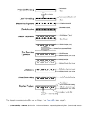
![Upgrading[1].laptop 2 th](https://image.slidesharecdn.com/upgrading1-140602222156-phpapp02/85/Upgrading-1-laptop-2-th-593-320.jpg)
![Upgrading[1].laptop 2 th](https://image.slidesharecdn.com/upgrading1-140602222156-phpapp02/85/Upgrading-1-laptop-2-th-594-320.jpg)
![Upgrading[1].laptop 2 th](https://image.slidesharecdn.com/upgrading1-140602222156-phpapp02/85/Upgrading-1-laptop-2-th-595-320.jpg)
![Upgrading[1].laptop 2 th](https://image.slidesharecdn.com/upgrading1-140602222156-phpapp02/85/Upgrading-1-laptop-2-th-596-320.jpg)
![Upgrading[1].laptop 2 th](https://image.slidesharecdn.com/upgrading1-140602222156-phpapp02/85/Upgrading-1-laptop-2-th-597-320.jpg)
![Upgrading[1].laptop 2 th](https://image.slidesharecdn.com/upgrading1-140602222156-phpapp02/85/Upgrading-1-laptop-2-th-598-320.jpg)
![Upgrading[1].laptop 2 th](https://image.slidesharecdn.com/upgrading1-140602222156-phpapp02/85/Upgrading-1-laptop-2-th-599-320.jpg)
![Upgrading[1].laptop 2 th](https://image.slidesharecdn.com/upgrading1-140602222156-phpapp02/85/Upgrading-1-laptop-2-th-600-320.jpg)
![Upgrading[1].laptop 2 th](https://image.slidesharecdn.com/upgrading1-140602222156-phpapp02/85/Upgrading-1-laptop-2-th-601-320.jpg)
![Upgrading[1].laptop 2 th](https://image.slidesharecdn.com/upgrading1-140602222156-phpapp02/85/Upgrading-1-laptop-2-th-602-320.jpg)
![Upgrading[1].laptop 2 th](https://image.slidesharecdn.com/upgrading1-140602222156-phpapp02/85/Upgrading-1-laptop-2-th-603-320.jpg)
![Upgrading[1].laptop 2 th](https://image.slidesharecdn.com/upgrading1-140602222156-phpapp02/85/Upgrading-1-laptop-2-th-604-320.jpg)
![Upgrading[1].laptop 2 th](https://image.slidesharecdn.com/upgrading1-140602222156-phpapp02/85/Upgrading-1-laptop-2-th-605-320.jpg)
![Upgrading[1].laptop 2 th](https://image.slidesharecdn.com/upgrading1-140602222156-phpapp02/85/Upgrading-1-laptop-2-th-606-320.jpg)
![Upgrading[1].laptop 2 th](https://image.slidesharecdn.com/upgrading1-140602222156-phpapp02/85/Upgrading-1-laptop-2-th-607-320.jpg)
![Upgrading[1].laptop 2 th](https://image.slidesharecdn.com/upgrading1-140602222156-phpapp02/85/Upgrading-1-laptop-2-th-608-320.jpg)
![Upgrading[1].laptop 2 th](https://image.slidesharecdn.com/upgrading1-140602222156-phpapp02/85/Upgrading-1-laptop-2-th-609-320.jpg)
![Upgrading[1].laptop 2 th](https://image.slidesharecdn.com/upgrading1-140602222156-phpapp02/85/Upgrading-1-laptop-2-th-610-320.jpg)
![Upgrading[1].laptop 2 th](https://image.slidesharecdn.com/upgrading1-140602222156-phpapp02/85/Upgrading-1-laptop-2-th-611-320.jpg)
![Upgrading[1].laptop 2 th](https://image.slidesharecdn.com/upgrading1-140602222156-phpapp02/85/Upgrading-1-laptop-2-th-612-320.jpg)
![Upgrading[1].laptop 2 th](https://image.slidesharecdn.com/upgrading1-140602222156-phpapp02/85/Upgrading-1-laptop-2-th-613-320.jpg)
![Upgrading[1].laptop 2 th](https://image.slidesharecdn.com/upgrading1-140602222156-phpapp02/85/Upgrading-1-laptop-2-th-614-320.jpg)
![Upgrading[1].laptop 2 th](https://image.slidesharecdn.com/upgrading1-140602222156-phpapp02/85/Upgrading-1-laptop-2-th-615-320.jpg)
![Upgrading[1].laptop 2 th](https://image.slidesharecdn.com/upgrading1-140602222156-phpapp02/85/Upgrading-1-laptop-2-th-616-320.jpg)
![Upgrading[1].laptop 2 th](https://image.slidesharecdn.com/upgrading1-140602222156-phpapp02/85/Upgrading-1-laptop-2-th-617-320.jpg)
![Upgrading[1].laptop 2 th](https://image.slidesharecdn.com/upgrading1-140602222156-phpapp02/85/Upgrading-1-laptop-2-th-618-320.jpg)
![Upgrading[1].laptop 2 th](https://image.slidesharecdn.com/upgrading1-140602222156-phpapp02/85/Upgrading-1-laptop-2-th-619-320.jpg)
![Upgrading[1].laptop 2 th](https://image.slidesharecdn.com/upgrading1-140602222156-phpapp02/85/Upgrading-1-laptop-2-th-620-320.jpg)
![Upgrading[1].laptop 2 th](https://image.slidesharecdn.com/upgrading1-140602222156-phpapp02/85/Upgrading-1-laptop-2-th-621-320.jpg)
![Upgrading[1].laptop 2 th](https://image.slidesharecdn.com/upgrading1-140602222156-phpapp02/85/Upgrading-1-laptop-2-th-622-320.jpg)
![Upgrading[1].laptop 2 th](https://image.slidesharecdn.com/upgrading1-140602222156-phpapp02/85/Upgrading-1-laptop-2-th-623-320.jpg)
![Upgrading[1].laptop 2 th](https://image.slidesharecdn.com/upgrading1-140602222156-phpapp02/85/Upgrading-1-laptop-2-th-624-320.jpg)
![Upgrading[1].laptop 2 th](https://image.slidesharecdn.com/upgrading1-140602222156-phpapp02/85/Upgrading-1-laptop-2-th-625-320.jpg)
![Upgrading[1].laptop 2 th](https://image.slidesharecdn.com/upgrading1-140602222156-phpapp02/85/Upgrading-1-laptop-2-th-626-320.jpg)
![Upgrading[1].laptop 2 th](https://image.slidesharecdn.com/upgrading1-140602222156-phpapp02/85/Upgrading-1-laptop-2-th-627-320.jpg)
![Upgrading[1].laptop 2 th](https://image.slidesharecdn.com/upgrading1-140602222156-phpapp02/85/Upgrading-1-laptop-2-th-628-320.jpg)
![Upgrading[1].laptop 2 th](https://image.slidesharecdn.com/upgrading1-140602222156-phpapp02/85/Upgrading-1-laptop-2-th-629-320.jpg)
![Upgrading[1].laptop 2 th](https://image.slidesharecdn.com/upgrading1-140602222156-phpapp02/85/Upgrading-1-laptop-2-th-630-320.jpg)
![Upgrading[1].laptop 2 th](https://image.slidesharecdn.com/upgrading1-140602222156-phpapp02/85/Upgrading-1-laptop-2-th-631-320.jpg)
![Upgrading[1].laptop 2 th](https://image.slidesharecdn.com/upgrading1-140602222156-phpapp02/85/Upgrading-1-laptop-2-th-632-320.jpg)
![Upgrading[1].laptop 2 th](https://image.slidesharecdn.com/upgrading1-140602222156-phpapp02/85/Upgrading-1-laptop-2-th-633-320.jpg)
![Upgrading[1].laptop 2 th](https://image.slidesharecdn.com/upgrading1-140602222156-phpapp02/85/Upgrading-1-laptop-2-th-634-320.jpg)
![Upgrading[1].laptop 2 th](https://image.slidesharecdn.com/upgrading1-140602222156-phpapp02/85/Upgrading-1-laptop-2-th-635-320.jpg)
![Upgrading[1].laptop 2 th](https://image.slidesharecdn.com/upgrading1-140602222156-phpapp02/85/Upgrading-1-laptop-2-th-636-320.jpg)
![Upgrading[1].laptop 2 th](https://image.slidesharecdn.com/upgrading1-140602222156-phpapp02/85/Upgrading-1-laptop-2-th-637-320.jpg)
![Upgrading[1].laptop 2 th](https://image.slidesharecdn.com/upgrading1-140602222156-phpapp02/85/Upgrading-1-laptop-2-th-638-320.jpg)
![Upgrading[1].laptop 2 th](https://image.slidesharecdn.com/upgrading1-140602222156-phpapp02/85/Upgrading-1-laptop-2-th-639-320.jpg)
![Upgrading[1].laptop 2 th](https://image.slidesharecdn.com/upgrading1-140602222156-phpapp02/85/Upgrading-1-laptop-2-th-640-320.jpg)
![Upgrading[1].laptop 2 th](https://image.slidesharecdn.com/upgrading1-140602222156-phpapp02/85/Upgrading-1-laptop-2-th-641-320.jpg)
![Upgrading[1].laptop 2 th](https://image.slidesharecdn.com/upgrading1-140602222156-phpapp02/85/Upgrading-1-laptop-2-th-642-320.jpg)
![Upgrading[1].laptop 2 th](https://image.slidesharecdn.com/upgrading1-140602222156-phpapp02/85/Upgrading-1-laptop-2-th-643-320.jpg)
![Upgrading[1].laptop 2 th](https://image.slidesharecdn.com/upgrading1-140602222156-phpapp02/85/Upgrading-1-laptop-2-th-644-320.jpg)
![Upgrading[1].laptop 2 th](https://image.slidesharecdn.com/upgrading1-140602222156-phpapp02/85/Upgrading-1-laptop-2-th-645-320.jpg)
![Upgrading[1].laptop 2 th](https://image.slidesharecdn.com/upgrading1-140602222156-phpapp02/85/Upgrading-1-laptop-2-th-646-320.jpg)
![Upgrading[1].laptop 2 th](https://image.slidesharecdn.com/upgrading1-140602222156-phpapp02/85/Upgrading-1-laptop-2-th-647-320.jpg)
![Upgrading[1].laptop 2 th](https://image.slidesharecdn.com/upgrading1-140602222156-phpapp02/85/Upgrading-1-laptop-2-th-648-320.jpg)
![Upgrading[1].laptop 2 th](https://image.slidesharecdn.com/upgrading1-140602222156-phpapp02/85/Upgrading-1-laptop-2-th-649-320.jpg)
![Upgrading[1].laptop 2 th](https://image.slidesharecdn.com/upgrading1-140602222156-phpapp02/85/Upgrading-1-laptop-2-th-650-320.jpg)
![Upgrading[1].laptop 2 th](https://image.slidesharecdn.com/upgrading1-140602222156-phpapp02/85/Upgrading-1-laptop-2-th-651-320.jpg)
![Upgrading[1].laptop 2 th](https://image.slidesharecdn.com/upgrading1-140602222156-phpapp02/85/Upgrading-1-laptop-2-th-652-320.jpg)
![Upgrading[1].laptop 2 th](https://image.slidesharecdn.com/upgrading1-140602222156-phpapp02/85/Upgrading-1-laptop-2-th-653-320.jpg)
![Upgrading[1].laptop 2 th](https://image.slidesharecdn.com/upgrading1-140602222156-phpapp02/85/Upgrading-1-laptop-2-th-654-320.jpg)
![Upgrading[1].laptop 2 th](https://image.slidesharecdn.com/upgrading1-140602222156-phpapp02/85/Upgrading-1-laptop-2-th-655-320.jpg)
![Upgrading[1].laptop 2 th](https://image.slidesharecdn.com/upgrading1-140602222156-phpapp02/85/Upgrading-1-laptop-2-th-656-320.jpg)
![Upgrading[1].laptop 2 th](https://image.slidesharecdn.com/upgrading1-140602222156-phpapp02/85/Upgrading-1-laptop-2-th-657-320.jpg)
![Upgrading[1].laptop 2 th](https://image.slidesharecdn.com/upgrading1-140602222156-phpapp02/85/Upgrading-1-laptop-2-th-658-320.jpg)
![Upgrading[1].laptop 2 th](https://image.slidesharecdn.com/upgrading1-140602222156-phpapp02/85/Upgrading-1-laptop-2-th-659-320.jpg)
![Upgrading[1].laptop 2 th](https://image.slidesharecdn.com/upgrading1-140602222156-phpapp02/85/Upgrading-1-laptop-2-th-660-320.jpg)
![Upgrading[1].laptop 2 th](https://image.slidesharecdn.com/upgrading1-140602222156-phpapp02/85/Upgrading-1-laptop-2-th-661-320.jpg)
![Upgrading[1].laptop 2 th](https://image.slidesharecdn.com/upgrading1-140602222156-phpapp02/85/Upgrading-1-laptop-2-th-662-320.jpg)
![Upgrading[1].laptop 2 th](https://image.slidesharecdn.com/upgrading1-140602222156-phpapp02/85/Upgrading-1-laptop-2-th-663-320.jpg)
![Upgrading[1].laptop 2 th](https://image.slidesharecdn.com/upgrading1-140602222156-phpapp02/85/Upgrading-1-laptop-2-th-664-320.jpg)
![Upgrading[1].laptop 2 th](https://image.slidesharecdn.com/upgrading1-140602222156-phpapp02/85/Upgrading-1-laptop-2-th-665-320.jpg)
![Upgrading[1].laptop 2 th](https://image.slidesharecdn.com/upgrading1-140602222156-phpapp02/85/Upgrading-1-laptop-2-th-666-320.jpg)
![Upgrading[1].laptop 2 th](https://image.slidesharecdn.com/upgrading1-140602222156-phpapp02/85/Upgrading-1-laptop-2-th-667-320.jpg)
![Upgrading[1].laptop 2 th](https://image.slidesharecdn.com/upgrading1-140602222156-phpapp02/85/Upgrading-1-laptop-2-th-668-320.jpg)
![Upgrading[1].laptop 2 th](https://image.slidesharecdn.com/upgrading1-140602222156-phpapp02/85/Upgrading-1-laptop-2-th-669-320.jpg)
![Upgrading[1].laptop 2 th](https://image.slidesharecdn.com/upgrading1-140602222156-phpapp02/85/Upgrading-1-laptop-2-th-670-320.jpg)
![Upgrading[1].laptop 2 th](https://image.slidesharecdn.com/upgrading1-140602222156-phpapp02/85/Upgrading-1-laptop-2-th-671-320.jpg)
![Upgrading[1].laptop 2 th](https://image.slidesharecdn.com/upgrading1-140602222156-phpapp02/85/Upgrading-1-laptop-2-th-672-320.jpg)
![Upgrading[1].laptop 2 th](https://image.slidesharecdn.com/upgrading1-140602222156-phpapp02/85/Upgrading-1-laptop-2-th-673-320.jpg)
![Upgrading[1].laptop 2 th](https://image.slidesharecdn.com/upgrading1-140602222156-phpapp02/85/Upgrading-1-laptop-2-th-674-320.jpg)
![Upgrading[1].laptop 2 th](https://image.slidesharecdn.com/upgrading1-140602222156-phpapp02/85/Upgrading-1-laptop-2-th-675-320.jpg)
![Upgrading[1].laptop 2 th](https://image.slidesharecdn.com/upgrading1-140602222156-phpapp02/85/Upgrading-1-laptop-2-th-676-320.jpg)
![Upgrading[1].laptop 2 th](https://image.slidesharecdn.com/upgrading1-140602222156-phpapp02/85/Upgrading-1-laptop-2-th-677-320.jpg)
![Upgrading[1].laptop 2 th](https://image.slidesharecdn.com/upgrading1-140602222156-phpapp02/85/Upgrading-1-laptop-2-th-678-320.jpg)
![Upgrading[1].laptop 2 th](https://image.slidesharecdn.com/upgrading1-140602222156-phpapp02/85/Upgrading-1-laptop-2-th-679-320.jpg)
![Upgrading[1].laptop 2 th](https://image.slidesharecdn.com/upgrading1-140602222156-phpapp02/85/Upgrading-1-laptop-2-th-680-320.jpg)
![Upgrading[1].laptop 2 th](https://image.slidesharecdn.com/upgrading1-140602222156-phpapp02/85/Upgrading-1-laptop-2-th-681-320.jpg)
![Upgrading[1].laptop 2 th](https://image.slidesharecdn.com/upgrading1-140602222156-phpapp02/85/Upgrading-1-laptop-2-th-682-320.jpg)
![Upgrading[1].laptop 2 th](https://image.slidesharecdn.com/upgrading1-140602222156-phpapp02/85/Upgrading-1-laptop-2-th-683-320.jpg)
![Upgrading[1].laptop 2 th](https://image.slidesharecdn.com/upgrading1-140602222156-phpapp02/85/Upgrading-1-laptop-2-th-684-320.jpg)
![Upgrading[1].laptop 2 th](https://image.slidesharecdn.com/upgrading1-140602222156-phpapp02/85/Upgrading-1-laptop-2-th-685-320.jpg)
![Upgrading[1].laptop 2 th](https://image.slidesharecdn.com/upgrading1-140602222156-phpapp02/85/Upgrading-1-laptop-2-th-686-320.jpg)
![Upgrading[1].laptop 2 th](https://image.slidesharecdn.com/upgrading1-140602222156-phpapp02/85/Upgrading-1-laptop-2-th-687-320.jpg)
![Upgrading[1].laptop 2 th](https://image.slidesharecdn.com/upgrading1-140602222156-phpapp02/85/Upgrading-1-laptop-2-th-688-320.jpg)
![Upgrading[1].laptop 2 th](https://image.slidesharecdn.com/upgrading1-140602222156-phpapp02/85/Upgrading-1-laptop-2-th-689-320.jpg)
![Upgrading[1].laptop 2 th](https://image.slidesharecdn.com/upgrading1-140602222156-phpapp02/85/Upgrading-1-laptop-2-th-690-320.jpg)
![Upgrading[1].laptop 2 th](https://image.slidesharecdn.com/upgrading1-140602222156-phpapp02/85/Upgrading-1-laptop-2-th-691-320.jpg)
![Upgrading[1].laptop 2 th](https://image.slidesharecdn.com/upgrading1-140602222156-phpapp02/85/Upgrading-1-laptop-2-th-692-320.jpg)
![Upgrading[1].laptop 2 th](https://image.slidesharecdn.com/upgrading1-140602222156-phpapp02/85/Upgrading-1-laptop-2-th-693-320.jpg)
![Upgrading[1].laptop 2 th](https://image.slidesharecdn.com/upgrading1-140602222156-phpapp02/85/Upgrading-1-laptop-2-th-694-320.jpg)
![Upgrading[1].laptop 2 th](https://image.slidesharecdn.com/upgrading1-140602222156-phpapp02/85/Upgrading-1-laptop-2-th-695-320.jpg)
![Upgrading[1].laptop 2 th](https://image.slidesharecdn.com/upgrading1-140602222156-phpapp02/85/Upgrading-1-laptop-2-th-696-320.jpg)
![Upgrading[1].laptop 2 th](https://image.slidesharecdn.com/upgrading1-140602222156-phpapp02/85/Upgrading-1-laptop-2-th-697-320.jpg)
![Upgrading[1].laptop 2 th](https://image.slidesharecdn.com/upgrading1-140602222156-phpapp02/85/Upgrading-1-laptop-2-th-698-320.jpg)
![Upgrading[1].laptop 2 th](https://image.slidesharecdn.com/upgrading1-140602222156-phpapp02/85/Upgrading-1-laptop-2-th-699-320.jpg)
![Upgrading[1].laptop 2 th](https://image.slidesharecdn.com/upgrading1-140602222156-phpapp02/85/Upgrading-1-laptop-2-th-700-320.jpg)
![Upgrading[1].laptop 2 th](https://image.slidesharecdn.com/upgrading1-140602222156-phpapp02/85/Upgrading-1-laptop-2-th-701-320.jpg)
![Upgrading[1].laptop 2 th](https://image.slidesharecdn.com/upgrading1-140602222156-phpapp02/85/Upgrading-1-laptop-2-th-702-320.jpg)
![Upgrading[1].laptop 2 th](https://image.slidesharecdn.com/upgrading1-140602222156-phpapp02/85/Upgrading-1-laptop-2-th-703-320.jpg)
![Upgrading[1].laptop 2 th](https://image.slidesharecdn.com/upgrading1-140602222156-phpapp02/85/Upgrading-1-laptop-2-th-704-320.jpg)
![Upgrading[1].laptop 2 th](https://image.slidesharecdn.com/upgrading1-140602222156-phpapp02/85/Upgrading-1-laptop-2-th-705-320.jpg)
![Upgrading[1].laptop 2 th](https://image.slidesharecdn.com/upgrading1-140602222156-phpapp02/85/Upgrading-1-laptop-2-th-706-320.jpg)
![Upgrading[1].laptop 2 th](https://image.slidesharecdn.com/upgrading1-140602222156-phpapp02/85/Upgrading-1-laptop-2-th-707-320.jpg)
![Upgrading[1].laptop 2 th](https://image.slidesharecdn.com/upgrading1-140602222156-phpapp02/85/Upgrading-1-laptop-2-th-708-320.jpg)
![Upgrading[1].laptop 2 th](https://image.slidesharecdn.com/upgrading1-140602222156-phpapp02/85/Upgrading-1-laptop-2-th-709-320.jpg)
![Upgrading[1].laptop 2 th](https://image.slidesharecdn.com/upgrading1-140602222156-phpapp02/85/Upgrading-1-laptop-2-th-710-320.jpg)
![Upgrading[1].laptop 2 th](https://image.slidesharecdn.com/upgrading1-140602222156-phpapp02/85/Upgrading-1-laptop-2-th-711-320.jpg)
![Upgrading[1].laptop 2 th](https://image.slidesharecdn.com/upgrading1-140602222156-phpapp02/85/Upgrading-1-laptop-2-th-712-320.jpg)
![Upgrading[1].laptop 2 th](https://image.slidesharecdn.com/upgrading1-140602222156-phpapp02/85/Upgrading-1-laptop-2-th-713-320.jpg)
![Upgrading[1].laptop 2 th](https://image.slidesharecdn.com/upgrading1-140602222156-phpapp02/85/Upgrading-1-laptop-2-th-714-320.jpg)
![Upgrading[1].laptop 2 th](https://image.slidesharecdn.com/upgrading1-140602222156-phpapp02/85/Upgrading-1-laptop-2-th-715-320.jpg)
![Upgrading[1].laptop 2 th](https://image.slidesharecdn.com/upgrading1-140602222156-phpapp02/85/Upgrading-1-laptop-2-th-716-320.jpg)
![Upgrading[1].laptop 2 th](https://image.slidesharecdn.com/upgrading1-140602222156-phpapp02/85/Upgrading-1-laptop-2-th-717-320.jpg)
![Upgrading[1].laptop 2 th](https://image.slidesharecdn.com/upgrading1-140602222156-phpapp02/85/Upgrading-1-laptop-2-th-718-320.jpg)
![Upgrading[1].laptop 2 th](https://image.slidesharecdn.com/upgrading1-140602222156-phpapp02/85/Upgrading-1-laptop-2-th-719-320.jpg)
![Upgrading[1].laptop 2 th](https://image.slidesharecdn.com/upgrading1-140602222156-phpapp02/85/Upgrading-1-laptop-2-th-720-320.jpg)
![Upgrading[1].laptop 2 th](https://image.slidesharecdn.com/upgrading1-140602222156-phpapp02/85/Upgrading-1-laptop-2-th-721-320.jpg)
![Upgrading[1].laptop 2 th](https://image.slidesharecdn.com/upgrading1-140602222156-phpapp02/85/Upgrading-1-laptop-2-th-722-320.jpg)
![Upgrading[1].laptop 2 th](https://image.slidesharecdn.com/upgrading1-140602222156-phpapp02/85/Upgrading-1-laptop-2-th-723-320.jpg)
![Upgrading[1].laptop 2 th](https://image.slidesharecdn.com/upgrading1-140602222156-phpapp02/85/Upgrading-1-laptop-2-th-724-320.jpg)
![Upgrading[1].laptop 2 th](https://image.slidesharecdn.com/upgrading1-140602222156-phpapp02/85/Upgrading-1-laptop-2-th-725-320.jpg)
![Upgrading[1].laptop 2 th](https://image.slidesharecdn.com/upgrading1-140602222156-phpapp02/85/Upgrading-1-laptop-2-th-726-320.jpg)
![Upgrading[1].laptop 2 th](https://image.slidesharecdn.com/upgrading1-140602222156-phpapp02/85/Upgrading-1-laptop-2-th-727-320.jpg)
![Upgrading[1].laptop 2 th](https://image.slidesharecdn.com/upgrading1-140602222156-phpapp02/85/Upgrading-1-laptop-2-th-728-320.jpg)
![Upgrading[1].laptop 2 th](https://image.slidesharecdn.com/upgrading1-140602222156-phpapp02/85/Upgrading-1-laptop-2-th-729-320.jpg)
![Upgrading[1].laptop 2 th](https://image.slidesharecdn.com/upgrading1-140602222156-phpapp02/85/Upgrading-1-laptop-2-th-730-320.jpg)
![Upgrading[1].laptop 2 th](https://image.slidesharecdn.com/upgrading1-140602222156-phpapp02/85/Upgrading-1-laptop-2-th-731-320.jpg)
![Upgrading[1].laptop 2 th](https://image.slidesharecdn.com/upgrading1-140602222156-phpapp02/85/Upgrading-1-laptop-2-th-732-320.jpg)
![Upgrading[1].laptop 2 th](https://image.slidesharecdn.com/upgrading1-140602222156-phpapp02/85/Upgrading-1-laptop-2-th-733-320.jpg)
![Upgrading[1].laptop 2 th](https://image.slidesharecdn.com/upgrading1-140602222156-phpapp02/85/Upgrading-1-laptop-2-th-734-320.jpg)
![Upgrading[1].laptop 2 th](https://image.slidesharecdn.com/upgrading1-140602222156-phpapp02/85/Upgrading-1-laptop-2-th-735-320.jpg)
![Upgrading[1].laptop 2 th](https://image.slidesharecdn.com/upgrading1-140602222156-phpapp02/85/Upgrading-1-laptop-2-th-736-320.jpg)
![Upgrading[1].laptop 2 th](https://image.slidesharecdn.com/upgrading1-140602222156-phpapp02/85/Upgrading-1-laptop-2-th-737-320.jpg)
![Upgrading[1].laptop 2 th](https://image.slidesharecdn.com/upgrading1-140602222156-phpapp02/85/Upgrading-1-laptop-2-th-738-320.jpg)
![Upgrading[1].laptop 2 th](https://image.slidesharecdn.com/upgrading1-140602222156-phpapp02/85/Upgrading-1-laptop-2-th-739-320.jpg)
![Upgrading[1].laptop 2 th](https://image.slidesharecdn.com/upgrading1-140602222156-phpapp02/85/Upgrading-1-laptop-2-th-740-320.jpg)
![Upgrading[1].laptop 2 th](https://image.slidesharecdn.com/upgrading1-140602222156-phpapp02/85/Upgrading-1-laptop-2-th-741-320.jpg)
![Upgrading[1].laptop 2 th](https://image.slidesharecdn.com/upgrading1-140602222156-phpapp02/85/Upgrading-1-laptop-2-th-742-320.jpg)
![Upgrading[1].laptop 2 th](https://image.slidesharecdn.com/upgrading1-140602222156-phpapp02/85/Upgrading-1-laptop-2-th-743-320.jpg)
![Upgrading[1].laptop 2 th](https://image.slidesharecdn.com/upgrading1-140602222156-phpapp02/85/Upgrading-1-laptop-2-th-744-320.jpg)
![Upgrading[1].laptop 2 th](https://image.slidesharecdn.com/upgrading1-140602222156-phpapp02/85/Upgrading-1-laptop-2-th-745-320.jpg)
![Upgrading[1].laptop 2 th](https://image.slidesharecdn.com/upgrading1-140602222156-phpapp02/85/Upgrading-1-laptop-2-th-746-320.jpg)
![Upgrading[1].laptop 2 th](https://image.slidesharecdn.com/upgrading1-140602222156-phpapp02/85/Upgrading-1-laptop-2-th-747-320.jpg)
![Upgrading[1].laptop 2 th](https://image.slidesharecdn.com/upgrading1-140602222156-phpapp02/85/Upgrading-1-laptop-2-th-748-320.jpg)
![Upgrading[1].laptop 2 th](https://image.slidesharecdn.com/upgrading1-140602222156-phpapp02/85/Upgrading-1-laptop-2-th-749-320.jpg)
![Upgrading[1].laptop 2 th](https://image.slidesharecdn.com/upgrading1-140602222156-phpapp02/85/Upgrading-1-laptop-2-th-750-320.jpg)
![Upgrading[1].laptop 2 th](https://image.slidesharecdn.com/upgrading1-140602222156-phpapp02/85/Upgrading-1-laptop-2-th-751-320.jpg)
![Upgrading[1].laptop 2 th](https://image.slidesharecdn.com/upgrading1-140602222156-phpapp02/85/Upgrading-1-laptop-2-th-752-320.jpg)
![Upgrading[1].laptop 2 th](https://image.slidesharecdn.com/upgrading1-140602222156-phpapp02/85/Upgrading-1-laptop-2-th-753-320.jpg)
![Upgrading[1].laptop 2 th](https://image.slidesharecdn.com/upgrading1-140602222156-phpapp02/85/Upgrading-1-laptop-2-th-754-320.jpg)
![Upgrading[1].laptop 2 th](https://image.slidesharecdn.com/upgrading1-140602222156-phpapp02/85/Upgrading-1-laptop-2-th-755-320.jpg)
![Upgrading[1].laptop 2 th](https://image.slidesharecdn.com/upgrading1-140602222156-phpapp02/85/Upgrading-1-laptop-2-th-756-320.jpg)
![Upgrading[1].laptop 2 th](https://image.slidesharecdn.com/upgrading1-140602222156-phpapp02/85/Upgrading-1-laptop-2-th-757-320.jpg)
![Upgrading[1].laptop 2 th](https://image.slidesharecdn.com/upgrading1-140602222156-phpapp02/85/Upgrading-1-laptop-2-th-758-320.jpg)
![Upgrading[1].laptop 2 th](https://image.slidesharecdn.com/upgrading1-140602222156-phpapp02/85/Upgrading-1-laptop-2-th-759-320.jpg)
![Upgrading[1].laptop 2 th](https://image.slidesharecdn.com/upgrading1-140602222156-phpapp02/85/Upgrading-1-laptop-2-th-760-320.jpg)
![Upgrading[1].laptop 2 th](https://image.slidesharecdn.com/upgrading1-140602222156-phpapp02/85/Upgrading-1-laptop-2-th-761-320.jpg)
![Upgrading[1].laptop 2 th](https://image.slidesharecdn.com/upgrading1-140602222156-phpapp02/85/Upgrading-1-laptop-2-th-762-320.jpg)
![Upgrading[1].laptop 2 th](https://image.slidesharecdn.com/upgrading1-140602222156-phpapp02/85/Upgrading-1-laptop-2-th-763-320.jpg)
![Upgrading[1].laptop 2 th](https://image.slidesharecdn.com/upgrading1-140602222156-phpapp02/85/Upgrading-1-laptop-2-th-764-320.jpg)
![Upgrading[1].laptop 2 th](https://image.slidesharecdn.com/upgrading1-140602222156-phpapp02/85/Upgrading-1-laptop-2-th-765-320.jpg)
![Upgrading[1].laptop 2 th](https://image.slidesharecdn.com/upgrading1-140602222156-phpapp02/85/Upgrading-1-laptop-2-th-766-320.jpg)
![Upgrading[1].laptop 2 th](https://image.slidesharecdn.com/upgrading1-140602222156-phpapp02/85/Upgrading-1-laptop-2-th-767-320.jpg)
![Upgrading[1].laptop 2 th](https://image.slidesharecdn.com/upgrading1-140602222156-phpapp02/85/Upgrading-1-laptop-2-th-768-320.jpg)
![Upgrading[1].laptop 2 th](https://image.slidesharecdn.com/upgrading1-140602222156-phpapp02/85/Upgrading-1-laptop-2-th-769-320.jpg)
![Upgrading[1].laptop 2 th](https://image.slidesharecdn.com/upgrading1-140602222156-phpapp02/85/Upgrading-1-laptop-2-th-770-320.jpg)
![Upgrading[1].laptop 2 th](https://image.slidesharecdn.com/upgrading1-140602222156-phpapp02/85/Upgrading-1-laptop-2-th-771-320.jpg)
![Upgrading[1].laptop 2 th](https://image.slidesharecdn.com/upgrading1-140602222156-phpapp02/85/Upgrading-1-laptop-2-th-772-320.jpg)
![Upgrading[1].laptop 2 th](https://image.slidesharecdn.com/upgrading1-140602222156-phpapp02/85/Upgrading-1-laptop-2-th-773-320.jpg)
![Upgrading[1].laptop 2 th](https://image.slidesharecdn.com/upgrading1-140602222156-phpapp02/85/Upgrading-1-laptop-2-th-774-320.jpg)
![Upgrading[1].laptop 2 th](https://image.slidesharecdn.com/upgrading1-140602222156-phpapp02/85/Upgrading-1-laptop-2-th-775-320.jpg)
![Upgrading[1].laptop 2 th](https://image.slidesharecdn.com/upgrading1-140602222156-phpapp02/85/Upgrading-1-laptop-2-th-776-320.jpg)
![Upgrading[1].laptop 2 th](https://image.slidesharecdn.com/upgrading1-140602222156-phpapp02/85/Upgrading-1-laptop-2-th-777-320.jpg)
![Upgrading[1].laptop 2 th](https://image.slidesharecdn.com/upgrading1-140602222156-phpapp02/85/Upgrading-1-laptop-2-th-778-320.jpg)
![Upgrading[1].laptop 2 th](https://image.slidesharecdn.com/upgrading1-140602222156-phpapp02/85/Upgrading-1-laptop-2-th-779-320.jpg)
![Upgrading[1].laptop 2 th](https://image.slidesharecdn.com/upgrading1-140602222156-phpapp02/85/Upgrading-1-laptop-2-th-780-320.jpg)
![Upgrading[1].laptop 2 th](https://image.slidesharecdn.com/upgrading1-140602222156-phpapp02/85/Upgrading-1-laptop-2-th-781-320.jpg)
![Upgrading[1].laptop 2 th](https://image.slidesharecdn.com/upgrading1-140602222156-phpapp02/85/Upgrading-1-laptop-2-th-782-320.jpg)
![Upgrading[1].laptop 2 th](https://image.slidesharecdn.com/upgrading1-140602222156-phpapp02/85/Upgrading-1-laptop-2-th-783-320.jpg)
![Upgrading[1].laptop 2 th](https://image.slidesharecdn.com/upgrading1-140602222156-phpapp02/85/Upgrading-1-laptop-2-th-784-320.jpg)
![Upgrading[1].laptop 2 th](https://image.slidesharecdn.com/upgrading1-140602222156-phpapp02/85/Upgrading-1-laptop-2-th-785-320.jpg)
![Upgrading[1].laptop 2 th](https://image.slidesharecdn.com/upgrading1-140602222156-phpapp02/85/Upgrading-1-laptop-2-th-786-320.jpg)
![Upgrading[1].laptop 2 th](https://image.slidesharecdn.com/upgrading1-140602222156-phpapp02/85/Upgrading-1-laptop-2-th-787-320.jpg)
![Upgrading[1].laptop 2 th](https://image.slidesharecdn.com/upgrading1-140602222156-phpapp02/85/Upgrading-1-laptop-2-th-788-320.jpg)
![Upgrading[1].laptop 2 th](https://image.slidesharecdn.com/upgrading1-140602222156-phpapp02/85/Upgrading-1-laptop-2-th-789-320.jpg)
![Upgrading[1].laptop 2 th](https://image.slidesharecdn.com/upgrading1-140602222156-phpapp02/85/Upgrading-1-laptop-2-th-790-320.jpg)
![Upgrading[1].laptop 2 th](https://image.slidesharecdn.com/upgrading1-140602222156-phpapp02/85/Upgrading-1-laptop-2-th-791-320.jpg)
![Upgrading[1].laptop 2 th](https://image.slidesharecdn.com/upgrading1-140602222156-phpapp02/85/Upgrading-1-laptop-2-th-792-320.jpg)
![Upgrading[1].laptop 2 th](https://image.slidesharecdn.com/upgrading1-140602222156-phpapp02/85/Upgrading-1-laptop-2-th-793-320.jpg)
![Upgrading[1].laptop 2 th](https://image.slidesharecdn.com/upgrading1-140602222156-phpapp02/85/Upgrading-1-laptop-2-th-794-320.jpg)
![Upgrading[1].laptop 2 th](https://image.slidesharecdn.com/upgrading1-140602222156-phpapp02/85/Upgrading-1-laptop-2-th-795-320.jpg)
![Upgrading[1].laptop 2 th](https://image.slidesharecdn.com/upgrading1-140602222156-phpapp02/85/Upgrading-1-laptop-2-th-796-320.jpg)
![Upgrading[1].laptop 2 th](https://image.slidesharecdn.com/upgrading1-140602222156-phpapp02/85/Upgrading-1-laptop-2-th-797-320.jpg)
![Upgrading[1].laptop 2 th](https://image.slidesharecdn.com/upgrading1-140602222156-phpapp02/85/Upgrading-1-laptop-2-th-798-320.jpg)
![Upgrading[1].laptop 2 th](https://image.slidesharecdn.com/upgrading1-140602222156-phpapp02/85/Upgrading-1-laptop-2-th-799-320.jpg)
![Upgrading[1].laptop 2 th](https://image.slidesharecdn.com/upgrading1-140602222156-phpapp02/85/Upgrading-1-laptop-2-th-800-320.jpg)
![Upgrading[1].laptop 2 th](https://image.slidesharecdn.com/upgrading1-140602222156-phpapp02/85/Upgrading-1-laptop-2-th-801-320.jpg)
![Upgrading[1].laptop 2 th](https://image.slidesharecdn.com/upgrading1-140602222156-phpapp02/85/Upgrading-1-laptop-2-th-802-320.jpg)
![Upgrading[1].laptop 2 th](https://image.slidesharecdn.com/upgrading1-140602222156-phpapp02/85/Upgrading-1-laptop-2-th-803-320.jpg)
![Upgrading[1].laptop 2 th](https://image.slidesharecdn.com/upgrading1-140602222156-phpapp02/85/Upgrading-1-laptop-2-th-804-320.jpg)
![Upgrading[1].laptop 2 th](https://image.slidesharecdn.com/upgrading1-140602222156-phpapp02/85/Upgrading-1-laptop-2-th-805-320.jpg)
![Upgrading[1].laptop 2 th](https://image.slidesharecdn.com/upgrading1-140602222156-phpapp02/85/Upgrading-1-laptop-2-th-806-320.jpg)
![Upgrading[1].laptop 2 th](https://image.slidesharecdn.com/upgrading1-140602222156-phpapp02/85/Upgrading-1-laptop-2-th-807-320.jpg)
![Upgrading[1].laptop 2 th](https://image.slidesharecdn.com/upgrading1-140602222156-phpapp02/85/Upgrading-1-laptop-2-th-808-320.jpg)
![Upgrading[1].laptop 2 th](https://image.slidesharecdn.com/upgrading1-140602222156-phpapp02/85/Upgrading-1-laptop-2-th-809-320.jpg)
![Upgrading[1].laptop 2 th](https://image.slidesharecdn.com/upgrading1-140602222156-phpapp02/85/Upgrading-1-laptop-2-th-810-320.jpg)
![Upgrading[1].laptop 2 th](https://image.slidesharecdn.com/upgrading1-140602222156-phpapp02/85/Upgrading-1-laptop-2-th-811-320.jpg)
![Upgrading[1].laptop 2 th](https://image.slidesharecdn.com/upgrading1-140602222156-phpapp02/85/Upgrading-1-laptop-2-th-812-320.jpg)
![Upgrading[1].laptop 2 th](https://image.slidesharecdn.com/upgrading1-140602222156-phpapp02/85/Upgrading-1-laptop-2-th-813-320.jpg)
![Upgrading[1].laptop 2 th](https://image.slidesharecdn.com/upgrading1-140602222156-phpapp02/85/Upgrading-1-laptop-2-th-814-320.jpg)
![Upgrading[1].laptop 2 th](https://image.slidesharecdn.com/upgrading1-140602222156-phpapp02/85/Upgrading-1-laptop-2-th-815-320.jpg)
![Upgrading[1].laptop 2 th](https://image.slidesharecdn.com/upgrading1-140602222156-phpapp02/85/Upgrading-1-laptop-2-th-816-320.jpg)
![Upgrading[1].laptop 2 th](https://image.slidesharecdn.com/upgrading1-140602222156-phpapp02/85/Upgrading-1-laptop-2-th-817-320.jpg)
![Upgrading[1].laptop 2 th](https://image.slidesharecdn.com/upgrading1-140602222156-phpapp02/85/Upgrading-1-laptop-2-th-818-320.jpg)
![Upgrading[1].laptop 2 th](https://image.slidesharecdn.com/upgrading1-140602222156-phpapp02/85/Upgrading-1-laptop-2-th-819-320.jpg)
![Upgrading[1].laptop 2 th](https://image.slidesharecdn.com/upgrading1-140602222156-phpapp02/85/Upgrading-1-laptop-2-th-820-320.jpg)
![Upgrading[1].laptop 2 th](https://image.slidesharecdn.com/upgrading1-140602222156-phpapp02/85/Upgrading-1-laptop-2-th-821-320.jpg)
![Upgrading[1].laptop 2 th](https://image.slidesharecdn.com/upgrading1-140602222156-phpapp02/85/Upgrading-1-laptop-2-th-822-320.jpg)
![Upgrading[1].laptop 2 th](https://image.slidesharecdn.com/upgrading1-140602222156-phpapp02/85/Upgrading-1-laptop-2-th-823-320.jpg)
![Upgrading[1].laptop 2 th](https://image.slidesharecdn.com/upgrading1-140602222156-phpapp02/85/Upgrading-1-laptop-2-th-824-320.jpg)
![Upgrading[1].laptop 2 th](https://image.slidesharecdn.com/upgrading1-140602222156-phpapp02/85/Upgrading-1-laptop-2-th-825-320.jpg)
![Upgrading[1].laptop 2 th](https://image.slidesharecdn.com/upgrading1-140602222156-phpapp02/85/Upgrading-1-laptop-2-th-826-320.jpg)
![Upgrading[1].laptop 2 th](https://image.slidesharecdn.com/upgrading1-140602222156-phpapp02/85/Upgrading-1-laptop-2-th-827-320.jpg)
![Upgrading[1].laptop 2 th](https://image.slidesharecdn.com/upgrading1-140602222156-phpapp02/85/Upgrading-1-laptop-2-th-828-320.jpg)
![Upgrading[1].laptop 2 th](https://image.slidesharecdn.com/upgrading1-140602222156-phpapp02/85/Upgrading-1-laptop-2-th-829-320.jpg)
![Upgrading[1].laptop 2 th](https://image.slidesharecdn.com/upgrading1-140602222156-phpapp02/85/Upgrading-1-laptop-2-th-830-320.jpg)
![Upgrading[1].laptop 2 th](https://image.slidesharecdn.com/upgrading1-140602222156-phpapp02/85/Upgrading-1-laptop-2-th-831-320.jpg)
![Upgrading[1].laptop 2 th](https://image.slidesharecdn.com/upgrading1-140602222156-phpapp02/85/Upgrading-1-laptop-2-th-832-320.jpg)
![Upgrading[1].laptop 2 th](https://image.slidesharecdn.com/upgrading1-140602222156-phpapp02/85/Upgrading-1-laptop-2-th-833-320.jpg)
![Upgrading[1].laptop 2 th](https://image.slidesharecdn.com/upgrading1-140602222156-phpapp02/85/Upgrading-1-laptop-2-th-834-320.jpg)
![Upgrading[1].laptop 2 th](https://image.slidesharecdn.com/upgrading1-140602222156-phpapp02/85/Upgrading-1-laptop-2-th-835-320.jpg)
![Upgrading[1].laptop 2 th](https://image.slidesharecdn.com/upgrading1-140602222156-phpapp02/85/Upgrading-1-laptop-2-th-836-320.jpg)
![Upgrading[1].laptop 2 th](https://image.slidesharecdn.com/upgrading1-140602222156-phpapp02/85/Upgrading-1-laptop-2-th-837-320.jpg)
![Upgrading[1].laptop 2 th](https://image.slidesharecdn.com/upgrading1-140602222156-phpapp02/85/Upgrading-1-laptop-2-th-838-320.jpg)
![Upgrading[1].laptop 2 th](https://image.slidesharecdn.com/upgrading1-140602222156-phpapp02/85/Upgrading-1-laptop-2-th-839-320.jpg)
![Upgrading[1].laptop 2 th](https://image.slidesharecdn.com/upgrading1-140602222156-phpapp02/85/Upgrading-1-laptop-2-th-840-320.jpg)
![Upgrading[1].laptop 2 th](https://image.slidesharecdn.com/upgrading1-140602222156-phpapp02/85/Upgrading-1-laptop-2-th-841-320.jpg)
![Upgrading[1].laptop 2 th](https://image.slidesharecdn.com/upgrading1-140602222156-phpapp02/85/Upgrading-1-laptop-2-th-842-320.jpg)
![Upgrading[1].laptop 2 th](https://image.slidesharecdn.com/upgrading1-140602222156-phpapp02/85/Upgrading-1-laptop-2-th-843-320.jpg)
![Upgrading[1].laptop 2 th](https://image.slidesharecdn.com/upgrading1-140602222156-phpapp02/85/Upgrading-1-laptop-2-th-844-320.jpg)
![Upgrading[1].laptop 2 th](https://image.slidesharecdn.com/upgrading1-140602222156-phpapp02/85/Upgrading-1-laptop-2-th-845-320.jpg)
![Upgrading[1].laptop 2 th](https://image.slidesharecdn.com/upgrading1-140602222156-phpapp02/85/Upgrading-1-laptop-2-th-846-320.jpg)
![Upgrading[1].laptop 2 th](https://image.slidesharecdn.com/upgrading1-140602222156-phpapp02/85/Upgrading-1-laptop-2-th-847-320.jpg)
![Upgrading[1].laptop 2 th](https://image.slidesharecdn.com/upgrading1-140602222156-phpapp02/85/Upgrading-1-laptop-2-th-848-320.jpg)
![Upgrading[1].laptop 2 th](https://image.slidesharecdn.com/upgrading1-140602222156-phpapp02/85/Upgrading-1-laptop-2-th-849-320.jpg)
![Upgrading[1].laptop 2 th](https://image.slidesharecdn.com/upgrading1-140602222156-phpapp02/85/Upgrading-1-laptop-2-th-850-320.jpg)
![Upgrading[1].laptop 2 th](https://image.slidesharecdn.com/upgrading1-140602222156-phpapp02/85/Upgrading-1-laptop-2-th-851-320.jpg)
![Upgrading[1].laptop 2 th](https://image.slidesharecdn.com/upgrading1-140602222156-phpapp02/85/Upgrading-1-laptop-2-th-852-320.jpg)
![Upgrading[1].laptop 2 th](https://image.slidesharecdn.com/upgrading1-140602222156-phpapp02/85/Upgrading-1-laptop-2-th-853-320.jpg)
![Upgrading[1].laptop 2 th](https://image.slidesharecdn.com/upgrading1-140602222156-phpapp02/85/Upgrading-1-laptop-2-th-854-320.jpg)
![Upgrading[1].laptop 2 th](https://image.slidesharecdn.com/upgrading1-140602222156-phpapp02/85/Upgrading-1-laptop-2-th-855-320.jpg)
![Upgrading[1].laptop 2 th](https://image.slidesharecdn.com/upgrading1-140602222156-phpapp02/85/Upgrading-1-laptop-2-th-856-320.jpg)
![Upgrading[1].laptop 2 th](https://image.slidesharecdn.com/upgrading1-140602222156-phpapp02/85/Upgrading-1-laptop-2-th-857-320.jpg)
![Upgrading[1].laptop 2 th](https://image.slidesharecdn.com/upgrading1-140602222156-phpapp02/85/Upgrading-1-laptop-2-th-858-320.jpg)
![Upgrading[1].laptop 2 th](https://image.slidesharecdn.com/upgrading1-140602222156-phpapp02/85/Upgrading-1-laptop-2-th-859-320.jpg)
![Upgrading[1].laptop 2 th](https://image.slidesharecdn.com/upgrading1-140602222156-phpapp02/85/Upgrading-1-laptop-2-th-860-320.jpg)
![Upgrading[1].laptop 2 th](https://image.slidesharecdn.com/upgrading1-140602222156-phpapp02/85/Upgrading-1-laptop-2-th-861-320.jpg)
![Upgrading[1].laptop 2 th](https://image.slidesharecdn.com/upgrading1-140602222156-phpapp02/85/Upgrading-1-laptop-2-th-862-320.jpg)
![Upgrading[1].laptop 2 th](https://image.slidesharecdn.com/upgrading1-140602222156-phpapp02/85/Upgrading-1-laptop-2-th-863-320.jpg)
![Upgrading[1].laptop 2 th](https://image.slidesharecdn.com/upgrading1-140602222156-phpapp02/85/Upgrading-1-laptop-2-th-864-320.jpg)
![Upgrading[1].laptop 2 th](https://image.slidesharecdn.com/upgrading1-140602222156-phpapp02/85/Upgrading-1-laptop-2-th-865-320.jpg)
![Upgrading[1].laptop 2 th](https://image.slidesharecdn.com/upgrading1-140602222156-phpapp02/85/Upgrading-1-laptop-2-th-866-320.jpg)
![Upgrading[1].laptop 2 th](https://image.slidesharecdn.com/upgrading1-140602222156-phpapp02/85/Upgrading-1-laptop-2-th-867-320.jpg)
![Upgrading[1].laptop 2 th](https://image.slidesharecdn.com/upgrading1-140602222156-phpapp02/85/Upgrading-1-laptop-2-th-868-320.jpg)
![Upgrading[1].laptop 2 th](https://image.slidesharecdn.com/upgrading1-140602222156-phpapp02/85/Upgrading-1-laptop-2-th-869-320.jpg)
![Upgrading[1].laptop 2 th](https://image.slidesharecdn.com/upgrading1-140602222156-phpapp02/85/Upgrading-1-laptop-2-th-870-320.jpg)
![Upgrading[1].laptop 2 th](https://image.slidesharecdn.com/upgrading1-140602222156-phpapp02/85/Upgrading-1-laptop-2-th-871-320.jpg)
![Upgrading[1].laptop 2 th](https://image.slidesharecdn.com/upgrading1-140602222156-phpapp02/85/Upgrading-1-laptop-2-th-872-320.jpg)
![Upgrading[1].laptop 2 th](https://image.slidesharecdn.com/upgrading1-140602222156-phpapp02/85/Upgrading-1-laptop-2-th-873-320.jpg)
![Upgrading[1].laptop 2 th](https://image.slidesharecdn.com/upgrading1-140602222156-phpapp02/85/Upgrading-1-laptop-2-th-874-320.jpg)
![Upgrading[1].laptop 2 th](https://image.slidesharecdn.com/upgrading1-140602222156-phpapp02/85/Upgrading-1-laptop-2-th-875-320.jpg)
![Upgrading[1].laptop 2 th](https://image.slidesharecdn.com/upgrading1-140602222156-phpapp02/85/Upgrading-1-laptop-2-th-876-320.jpg)
![Upgrading[1].laptop 2 th](https://image.slidesharecdn.com/upgrading1-140602222156-phpapp02/85/Upgrading-1-laptop-2-th-877-320.jpg)
![Upgrading[1].laptop 2 th](https://image.slidesharecdn.com/upgrading1-140602222156-phpapp02/85/Upgrading-1-laptop-2-th-878-320.jpg)
![Upgrading[1].laptop 2 th](https://image.slidesharecdn.com/upgrading1-140602222156-phpapp02/85/Upgrading-1-laptop-2-th-879-320.jpg)
![Upgrading[1].laptop 2 th](https://image.slidesharecdn.com/upgrading1-140602222156-phpapp02/85/Upgrading-1-laptop-2-th-880-320.jpg)
![Upgrading[1].laptop 2 th](https://image.slidesharecdn.com/upgrading1-140602222156-phpapp02/85/Upgrading-1-laptop-2-th-881-320.jpg)
![Upgrading[1].laptop 2 th](https://image.slidesharecdn.com/upgrading1-140602222156-phpapp02/85/Upgrading-1-laptop-2-th-882-320.jpg)
![Upgrading[1].laptop 2 th](https://image.slidesharecdn.com/upgrading1-140602222156-phpapp02/85/Upgrading-1-laptop-2-th-883-320.jpg)
![Upgrading[1].laptop 2 th](https://image.slidesharecdn.com/upgrading1-140602222156-phpapp02/85/Upgrading-1-laptop-2-th-884-320.jpg)
![Upgrading[1].laptop 2 th](https://image.slidesharecdn.com/upgrading1-140602222156-phpapp02/85/Upgrading-1-laptop-2-th-885-320.jpg)
![Upgrading[1].laptop 2 th](https://image.slidesharecdn.com/upgrading1-140602222156-phpapp02/85/Upgrading-1-laptop-2-th-886-320.jpg)
![Upgrading[1].laptop 2 th](https://image.slidesharecdn.com/upgrading1-140602222156-phpapp02/85/Upgrading-1-laptop-2-th-887-320.jpg)
![Upgrading[1].laptop 2 th](https://image.slidesharecdn.com/upgrading1-140602222156-phpapp02/85/Upgrading-1-laptop-2-th-888-320.jpg)
![Upgrading[1].laptop 2 th](https://image.slidesharecdn.com/upgrading1-140602222156-phpapp02/85/Upgrading-1-laptop-2-th-889-320.jpg)
![Upgrading[1].laptop 2 th](https://image.slidesharecdn.com/upgrading1-140602222156-phpapp02/85/Upgrading-1-laptop-2-th-890-320.jpg)
![Upgrading[1].laptop 2 th](https://image.slidesharecdn.com/upgrading1-140602222156-phpapp02/85/Upgrading-1-laptop-2-th-891-320.jpg)
![Upgrading[1].laptop 2 th](https://image.slidesharecdn.com/upgrading1-140602222156-phpapp02/85/Upgrading-1-laptop-2-th-892-320.jpg)
![Upgrading[1].laptop 2 th](https://image.slidesharecdn.com/upgrading1-140602222156-phpapp02/85/Upgrading-1-laptop-2-th-893-320.jpg)
![Upgrading[1].laptop 2 th](https://image.slidesharecdn.com/upgrading1-140602222156-phpapp02/85/Upgrading-1-laptop-2-th-894-320.jpg)
![Upgrading[1].laptop 2 th](https://image.slidesharecdn.com/upgrading1-140602222156-phpapp02/85/Upgrading-1-laptop-2-th-895-320.jpg)
![Upgrading[1].laptop 2 th](https://image.slidesharecdn.com/upgrading1-140602222156-phpapp02/85/Upgrading-1-laptop-2-th-896-320.jpg)
![Upgrading[1].laptop 2 th](https://image.slidesharecdn.com/upgrading1-140602222156-phpapp02/85/Upgrading-1-laptop-2-th-897-320.jpg)
![Upgrading[1].laptop 2 th](https://image.slidesharecdn.com/upgrading1-140602222156-phpapp02/85/Upgrading-1-laptop-2-th-898-320.jpg)
![Upgrading[1].laptop 2 th](https://image.slidesharecdn.com/upgrading1-140602222156-phpapp02/85/Upgrading-1-laptop-2-th-899-320.jpg)
![Upgrading[1].laptop 2 th](https://image.slidesharecdn.com/upgrading1-140602222156-phpapp02/85/Upgrading-1-laptop-2-th-900-320.jpg)
![Upgrading[1].laptop 2 th](https://image.slidesharecdn.com/upgrading1-140602222156-phpapp02/85/Upgrading-1-laptop-2-th-901-320.jpg)
![Upgrading[1].laptop 2 th](https://image.slidesharecdn.com/upgrading1-140602222156-phpapp02/85/Upgrading-1-laptop-2-th-902-320.jpg)
![Upgrading[1].laptop 2 th](https://image.slidesharecdn.com/upgrading1-140602222156-phpapp02/85/Upgrading-1-laptop-2-th-903-320.jpg)
![Upgrading[1].laptop 2 th](https://image.slidesharecdn.com/upgrading1-140602222156-phpapp02/85/Upgrading-1-laptop-2-th-904-320.jpg)
![Upgrading[1].laptop 2 th](https://image.slidesharecdn.com/upgrading1-140602222156-phpapp02/85/Upgrading-1-laptop-2-th-905-320.jpg)
![Upgrading[1].laptop 2 th](https://image.slidesharecdn.com/upgrading1-140602222156-phpapp02/85/Upgrading-1-laptop-2-th-906-320.jpg)
![Upgrading[1].laptop 2 th](https://image.slidesharecdn.com/upgrading1-140602222156-phpapp02/85/Upgrading-1-laptop-2-th-907-320.jpg)
![Upgrading[1].laptop 2 th](https://image.slidesharecdn.com/upgrading1-140602222156-phpapp02/85/Upgrading-1-laptop-2-th-908-320.jpg)
![Upgrading[1].laptop 2 th](https://image.slidesharecdn.com/upgrading1-140602222156-phpapp02/85/Upgrading-1-laptop-2-th-909-320.jpg)
![Upgrading[1].laptop 2 th](https://image.slidesharecdn.com/upgrading1-140602222156-phpapp02/85/Upgrading-1-laptop-2-th-910-320.jpg)
![Upgrading[1].laptop 2 th](https://image.slidesharecdn.com/upgrading1-140602222156-phpapp02/85/Upgrading-1-laptop-2-th-911-320.jpg)
![Upgrading[1].laptop 2 th](https://image.slidesharecdn.com/upgrading1-140602222156-phpapp02/85/Upgrading-1-laptop-2-th-912-320.jpg)
![Upgrading[1].laptop 2 th](https://image.slidesharecdn.com/upgrading1-140602222156-phpapp02/85/Upgrading-1-laptop-2-th-913-320.jpg)
![Upgrading[1].laptop 2 th](https://image.slidesharecdn.com/upgrading1-140602222156-phpapp02/85/Upgrading-1-laptop-2-th-914-320.jpg)
![Upgrading[1].laptop 2 th](https://image.slidesharecdn.com/upgrading1-140602222156-phpapp02/85/Upgrading-1-laptop-2-th-915-320.jpg)
![Upgrading[1].laptop 2 th](https://image.slidesharecdn.com/upgrading1-140602222156-phpapp02/85/Upgrading-1-laptop-2-th-916-320.jpg)
![Upgrading[1].laptop 2 th](https://image.slidesharecdn.com/upgrading1-140602222156-phpapp02/85/Upgrading-1-laptop-2-th-917-320.jpg)
![Upgrading[1].laptop 2 th](https://image.slidesharecdn.com/upgrading1-140602222156-phpapp02/85/Upgrading-1-laptop-2-th-918-320.jpg)
![Upgrading[1].laptop 2 th](https://image.slidesharecdn.com/upgrading1-140602222156-phpapp02/85/Upgrading-1-laptop-2-th-919-320.jpg)
![Upgrading[1].laptop 2 th](https://image.slidesharecdn.com/upgrading1-140602222156-phpapp02/85/Upgrading-1-laptop-2-th-920-320.jpg)
![Upgrading[1].laptop 2 th](https://image.slidesharecdn.com/upgrading1-140602222156-phpapp02/85/Upgrading-1-laptop-2-th-921-320.jpg)
![Upgrading[1].laptop 2 th](https://image.slidesharecdn.com/upgrading1-140602222156-phpapp02/85/Upgrading-1-laptop-2-th-922-320.jpg)
![Upgrading[1].laptop 2 th](https://image.slidesharecdn.com/upgrading1-140602222156-phpapp02/85/Upgrading-1-laptop-2-th-923-320.jpg)
![Upgrading[1].laptop 2 th](https://image.slidesharecdn.com/upgrading1-140602222156-phpapp02/85/Upgrading-1-laptop-2-th-924-320.jpg)
![Upgrading[1].laptop 2 th](https://image.slidesharecdn.com/upgrading1-140602222156-phpapp02/85/Upgrading-1-laptop-2-th-925-320.jpg)
![Upgrading[1].laptop 2 th](https://image.slidesharecdn.com/upgrading1-140602222156-phpapp02/85/Upgrading-1-laptop-2-th-926-320.jpg)
![Upgrading[1].laptop 2 th](https://image.slidesharecdn.com/upgrading1-140602222156-phpapp02/85/Upgrading-1-laptop-2-th-927-320.jpg)
![Upgrading[1].laptop 2 th](https://image.slidesharecdn.com/upgrading1-140602222156-phpapp02/85/Upgrading-1-laptop-2-th-928-320.jpg)
![Upgrading[1].laptop 2 th](https://image.slidesharecdn.com/upgrading1-140602222156-phpapp02/85/Upgrading-1-laptop-2-th-929-320.jpg)
![Upgrading[1].laptop 2 th](https://image.slidesharecdn.com/upgrading1-140602222156-phpapp02/85/Upgrading-1-laptop-2-th-930-320.jpg)
![Upgrading[1].laptop 2 th](https://image.slidesharecdn.com/upgrading1-140602222156-phpapp02/85/Upgrading-1-laptop-2-th-931-320.jpg)
![Upgrading[1].laptop 2 th](https://image.slidesharecdn.com/upgrading1-140602222156-phpapp02/85/Upgrading-1-laptop-2-th-932-320.jpg)
![Upgrading[1].laptop 2 th](https://image.slidesharecdn.com/upgrading1-140602222156-phpapp02/85/Upgrading-1-laptop-2-th-933-320.jpg)
![Upgrading[1].laptop 2 th](https://image.slidesharecdn.com/upgrading1-140602222156-phpapp02/85/Upgrading-1-laptop-2-th-934-320.jpg)
![Upgrading[1].laptop 2 th](https://image.slidesharecdn.com/upgrading1-140602222156-phpapp02/85/Upgrading-1-laptop-2-th-935-320.jpg)
![Upgrading[1].laptop 2 th](https://image.slidesharecdn.com/upgrading1-140602222156-phpapp02/85/Upgrading-1-laptop-2-th-936-320.jpg)
![Upgrading[1].laptop 2 th](https://image.slidesharecdn.com/upgrading1-140602222156-phpapp02/85/Upgrading-1-laptop-2-th-937-320.jpg)
![Upgrading[1].laptop 2 th](https://image.slidesharecdn.com/upgrading1-140602222156-phpapp02/85/Upgrading-1-laptop-2-th-938-320.jpg)
![Upgrading[1].laptop 2 th](https://image.slidesharecdn.com/upgrading1-140602222156-phpapp02/85/Upgrading-1-laptop-2-th-939-320.jpg)
![Upgrading[1].laptop 2 th](https://image.slidesharecdn.com/upgrading1-140602222156-phpapp02/85/Upgrading-1-laptop-2-th-940-320.jpg)
![Upgrading[1].laptop 2 th](https://image.slidesharecdn.com/upgrading1-140602222156-phpapp02/85/Upgrading-1-laptop-2-th-941-320.jpg)
![Upgrading[1].laptop 2 th](https://image.slidesharecdn.com/upgrading1-140602222156-phpapp02/85/Upgrading-1-laptop-2-th-942-320.jpg)
![Upgrading[1].laptop 2 th](https://image.slidesharecdn.com/upgrading1-140602222156-phpapp02/85/Upgrading-1-laptop-2-th-943-320.jpg)
![Upgrading[1].laptop 2 th](https://image.slidesharecdn.com/upgrading1-140602222156-phpapp02/85/Upgrading-1-laptop-2-th-944-320.jpg)
![Upgrading[1].laptop 2 th](https://image.slidesharecdn.com/upgrading1-140602222156-phpapp02/85/Upgrading-1-laptop-2-th-945-320.jpg)
![Upgrading[1].laptop 2 th](https://image.slidesharecdn.com/upgrading1-140602222156-phpapp02/85/Upgrading-1-laptop-2-th-946-320.jpg)
![Upgrading[1].laptop 2 th](https://image.slidesharecdn.com/upgrading1-140602222156-phpapp02/85/Upgrading-1-laptop-2-th-947-320.jpg)
![Upgrading[1].laptop 2 th](https://image.slidesharecdn.com/upgrading1-140602222156-phpapp02/85/Upgrading-1-laptop-2-th-948-320.jpg)
![Upgrading[1].laptop 2 th](https://image.slidesharecdn.com/upgrading1-140602222156-phpapp02/85/Upgrading-1-laptop-2-th-949-320.jpg)
![Upgrading[1].laptop 2 th](https://image.slidesharecdn.com/upgrading1-140602222156-phpapp02/85/Upgrading-1-laptop-2-th-950-320.jpg)
![Upgrading[1].laptop 2 th](https://image.slidesharecdn.com/upgrading1-140602222156-phpapp02/85/Upgrading-1-laptop-2-th-951-320.jpg)
![Upgrading[1].laptop 2 th](https://image.slidesharecdn.com/upgrading1-140602222156-phpapp02/85/Upgrading-1-laptop-2-th-952-320.jpg)
![Upgrading[1].laptop 2 th](https://image.slidesharecdn.com/upgrading1-140602222156-phpapp02/85/Upgrading-1-laptop-2-th-953-320.jpg)
![Upgrading[1].laptop 2 th](https://image.slidesharecdn.com/upgrading1-140602222156-phpapp02/85/Upgrading-1-laptop-2-th-954-320.jpg)
![Upgrading[1].laptop 2 th](https://image.slidesharecdn.com/upgrading1-140602222156-phpapp02/85/Upgrading-1-laptop-2-th-955-320.jpg)
![Upgrading[1].laptop 2 th](https://image.slidesharecdn.com/upgrading1-140602222156-phpapp02/85/Upgrading-1-laptop-2-th-956-320.jpg)
![Upgrading[1].laptop 2 th](https://image.slidesharecdn.com/upgrading1-140602222156-phpapp02/85/Upgrading-1-laptop-2-th-957-320.jpg)
![Upgrading[1].laptop 2 th](https://image.slidesharecdn.com/upgrading1-140602222156-phpapp02/85/Upgrading-1-laptop-2-th-958-320.jpg)
![Upgrading[1].laptop 2 th](https://image.slidesharecdn.com/upgrading1-140602222156-phpapp02/85/Upgrading-1-laptop-2-th-959-320.jpg)
![Upgrading[1].laptop 2 th](https://image.slidesharecdn.com/upgrading1-140602222156-phpapp02/85/Upgrading-1-laptop-2-th-960-320.jpg)
![Upgrading[1].laptop 2 th](https://image.slidesharecdn.com/upgrading1-140602222156-phpapp02/85/Upgrading-1-laptop-2-th-961-320.jpg)
![Upgrading[1].laptop 2 th](https://image.slidesharecdn.com/upgrading1-140602222156-phpapp02/85/Upgrading-1-laptop-2-th-962-320.jpg)
![Upgrading[1].laptop 2 th](https://image.slidesharecdn.com/upgrading1-140602222156-phpapp02/85/Upgrading-1-laptop-2-th-963-320.jpg)
![Upgrading[1].laptop 2 th](https://image.slidesharecdn.com/upgrading1-140602222156-phpapp02/85/Upgrading-1-laptop-2-th-964-320.jpg)
![Upgrading[1].laptop 2 th](https://image.slidesharecdn.com/upgrading1-140602222156-phpapp02/85/Upgrading-1-laptop-2-th-965-320.jpg)
![Upgrading[1].laptop 2 th](https://image.slidesharecdn.com/upgrading1-140602222156-phpapp02/85/Upgrading-1-laptop-2-th-966-320.jpg)
![Upgrading[1].laptop 2 th](https://image.slidesharecdn.com/upgrading1-140602222156-phpapp02/85/Upgrading-1-laptop-2-th-967-320.jpg)
![Upgrading[1].laptop 2 th](https://image.slidesharecdn.com/upgrading1-140602222156-phpapp02/85/Upgrading-1-laptop-2-th-968-320.jpg)
![Upgrading[1].laptop 2 th](https://image.slidesharecdn.com/upgrading1-140602222156-phpapp02/85/Upgrading-1-laptop-2-th-969-320.jpg)
![Upgrading[1].laptop 2 th](https://image.slidesharecdn.com/upgrading1-140602222156-phpapp02/85/Upgrading-1-laptop-2-th-970-320.jpg)
![Upgrading[1].laptop 2 th](https://image.slidesharecdn.com/upgrading1-140602222156-phpapp02/85/Upgrading-1-laptop-2-th-971-320.jpg)
![Upgrading[1].laptop 2 th](https://image.slidesharecdn.com/upgrading1-140602222156-phpapp02/85/Upgrading-1-laptop-2-th-972-320.jpg)
![Upgrading[1].laptop 2 th](https://image.slidesharecdn.com/upgrading1-140602222156-phpapp02/85/Upgrading-1-laptop-2-th-973-320.jpg)
![Upgrading[1].laptop 2 th](https://image.slidesharecdn.com/upgrading1-140602222156-phpapp02/85/Upgrading-1-laptop-2-th-974-320.jpg)
![Upgrading[1].laptop 2 th](https://image.slidesharecdn.com/upgrading1-140602222156-phpapp02/85/Upgrading-1-laptop-2-th-975-320.jpg)
![Upgrading[1].laptop 2 th](https://image.slidesharecdn.com/upgrading1-140602222156-phpapp02/85/Upgrading-1-laptop-2-th-976-320.jpg)
![Upgrading[1].laptop 2 th](https://image.slidesharecdn.com/upgrading1-140602222156-phpapp02/85/Upgrading-1-laptop-2-th-977-320.jpg)
![Upgrading[1].laptop 2 th](https://image.slidesharecdn.com/upgrading1-140602222156-phpapp02/85/Upgrading-1-laptop-2-th-978-320.jpg)
![Upgrading[1].laptop 2 th](https://image.slidesharecdn.com/upgrading1-140602222156-phpapp02/85/Upgrading-1-laptop-2-th-979-320.jpg)
![Upgrading[1].laptop 2 th](https://image.slidesharecdn.com/upgrading1-140602222156-phpapp02/85/Upgrading-1-laptop-2-th-980-320.jpg)
![Upgrading[1].laptop 2 th](https://image.slidesharecdn.com/upgrading1-140602222156-phpapp02/85/Upgrading-1-laptop-2-th-981-320.jpg)
![Upgrading[1].laptop 2 th](https://image.slidesharecdn.com/upgrading1-140602222156-phpapp02/85/Upgrading-1-laptop-2-th-982-320.jpg)
![Upgrading[1].laptop 2 th](https://image.slidesharecdn.com/upgrading1-140602222156-phpapp02/85/Upgrading-1-laptop-2-th-983-320.jpg)
![Upgrading[1].laptop 2 th](https://image.slidesharecdn.com/upgrading1-140602222156-phpapp02/85/Upgrading-1-laptop-2-th-984-320.jpg)
![Upgrading[1].laptop 2 th](https://image.slidesharecdn.com/upgrading1-140602222156-phpapp02/85/Upgrading-1-laptop-2-th-985-320.jpg)
![Upgrading[1].laptop 2 th](https://image.slidesharecdn.com/upgrading1-140602222156-phpapp02/85/Upgrading-1-laptop-2-th-986-320.jpg)
![Upgrading[1].laptop 2 th](https://image.slidesharecdn.com/upgrading1-140602222156-phpapp02/85/Upgrading-1-laptop-2-th-987-320.jpg)
![Upgrading[1].laptop 2 th](https://image.slidesharecdn.com/upgrading1-140602222156-phpapp02/85/Upgrading-1-laptop-2-th-988-320.jpg)
![Upgrading[1].laptop 2 th](https://image.slidesharecdn.com/upgrading1-140602222156-phpapp02/85/Upgrading-1-laptop-2-th-989-320.jpg)
![Upgrading[1].laptop 2 th](https://image.slidesharecdn.com/upgrading1-140602222156-phpapp02/85/Upgrading-1-laptop-2-th-990-320.jpg)
![Upgrading[1].laptop 2 th](https://image.slidesharecdn.com/upgrading1-140602222156-phpapp02/85/Upgrading-1-laptop-2-th-991-320.jpg)
![Upgrading[1].laptop 2 th](https://image.slidesharecdn.com/upgrading1-140602222156-phpapp02/85/Upgrading-1-laptop-2-th-992-320.jpg)
![Upgrading[1].laptop 2 th](https://image.slidesharecdn.com/upgrading1-140602222156-phpapp02/85/Upgrading-1-laptop-2-th-993-320.jpg)
![Upgrading[1].laptop 2 th](https://image.slidesharecdn.com/upgrading1-140602222156-phpapp02/85/Upgrading-1-laptop-2-th-994-320.jpg)
![Upgrading[1].laptop 2 th](https://image.slidesharecdn.com/upgrading1-140602222156-phpapp02/85/Upgrading-1-laptop-2-th-995-320.jpg)
![Upgrading[1].laptop 2 th](https://image.slidesharecdn.com/upgrading1-140602222156-phpapp02/85/Upgrading-1-laptop-2-th-996-320.jpg)
![Upgrading[1].laptop 2 th](https://image.slidesharecdn.com/upgrading1-140602222156-phpapp02/85/Upgrading-1-laptop-2-th-997-320.jpg)
![Upgrading[1].laptop 2 th](https://image.slidesharecdn.com/upgrading1-140602222156-phpapp02/85/Upgrading-1-laptop-2-th-998-320.jpg)
![Upgrading[1].laptop 2 th](https://image.slidesharecdn.com/upgrading1-140602222156-phpapp02/85/Upgrading-1-laptop-2-th-999-320.jpg)
![Upgrading[1].laptop 2 th](https://image.slidesharecdn.com/upgrading1-140602222156-phpapp02/85/Upgrading-1-laptop-2-th-1000-320.jpg)
![Upgrading[1].laptop 2 th](https://image.slidesharecdn.com/upgrading1-140602222156-phpapp02/85/Upgrading-1-laptop-2-th-1001-320.jpg)
![Upgrading[1].laptop 2 th](https://image.slidesharecdn.com/upgrading1-140602222156-phpapp02/85/Upgrading-1-laptop-2-th-1002-320.jpg)
![Upgrading[1].laptop 2 th](https://image.slidesharecdn.com/upgrading1-140602222156-phpapp02/85/Upgrading-1-laptop-2-th-1003-320.jpg)
![Upgrading[1].laptop 2 th](https://image.slidesharecdn.com/upgrading1-140602222156-phpapp02/85/Upgrading-1-laptop-2-th-1004-320.jpg)
![Upgrading[1].laptop 2 th](https://image.slidesharecdn.com/upgrading1-140602222156-phpapp02/85/Upgrading-1-laptop-2-th-1005-320.jpg)
![Upgrading[1].laptop 2 th](https://image.slidesharecdn.com/upgrading1-140602222156-phpapp02/85/Upgrading-1-laptop-2-th-1006-320.jpg)
![Upgrading[1].laptop 2 th](https://image.slidesharecdn.com/upgrading1-140602222156-phpapp02/85/Upgrading-1-laptop-2-th-1007-320.jpg)
![Upgrading[1].laptop 2 th](https://image.slidesharecdn.com/upgrading1-140602222156-phpapp02/85/Upgrading-1-laptop-2-th-1008-320.jpg)
![Upgrading[1].laptop 2 th](https://image.slidesharecdn.com/upgrading1-140602222156-phpapp02/85/Upgrading-1-laptop-2-th-1009-320.jpg)
![Upgrading[1].laptop 2 th](https://image.slidesharecdn.com/upgrading1-140602222156-phpapp02/85/Upgrading-1-laptop-2-th-1010-320.jpg)
![Upgrading[1].laptop 2 th](https://image.slidesharecdn.com/upgrading1-140602222156-phpapp02/85/Upgrading-1-laptop-2-th-1011-320.jpg)
![Upgrading[1].laptop 2 th](https://image.slidesharecdn.com/upgrading1-140602222156-phpapp02/85/Upgrading-1-laptop-2-th-1012-320.jpg)
![Upgrading[1].laptop 2 th](https://image.slidesharecdn.com/upgrading1-140602222156-phpapp02/85/Upgrading-1-laptop-2-th-1013-320.jpg)
![Upgrading[1].laptop 2 th](https://image.slidesharecdn.com/upgrading1-140602222156-phpapp02/85/Upgrading-1-laptop-2-th-1014-320.jpg)
![Upgrading[1].laptop 2 th](https://image.slidesharecdn.com/upgrading1-140602222156-phpapp02/85/Upgrading-1-laptop-2-th-1015-320.jpg)
![Upgrading[1].laptop 2 th](https://image.slidesharecdn.com/upgrading1-140602222156-phpapp02/85/Upgrading-1-laptop-2-th-1016-320.jpg)
![Upgrading[1].laptop 2 th](https://image.slidesharecdn.com/upgrading1-140602222156-phpapp02/85/Upgrading-1-laptop-2-th-1017-320.jpg)
![Upgrading[1].laptop 2 th](https://image.slidesharecdn.com/upgrading1-140602222156-phpapp02/85/Upgrading-1-laptop-2-th-1018-320.jpg)
![Upgrading[1].laptop 2 th](https://image.slidesharecdn.com/upgrading1-140602222156-phpapp02/85/Upgrading-1-laptop-2-th-1019-320.jpg)
![Upgrading[1].laptop 2 th](https://image.slidesharecdn.com/upgrading1-140602222156-phpapp02/85/Upgrading-1-laptop-2-th-1020-320.jpg)
![Upgrading[1].laptop 2 th](https://image.slidesharecdn.com/upgrading1-140602222156-phpapp02/85/Upgrading-1-laptop-2-th-1021-320.jpg)
![Upgrading[1].laptop 2 th](https://image.slidesharecdn.com/upgrading1-140602222156-phpapp02/85/Upgrading-1-laptop-2-th-1022-320.jpg)
![Upgrading[1].laptop 2 th](https://image.slidesharecdn.com/upgrading1-140602222156-phpapp02/85/Upgrading-1-laptop-2-th-1023-320.jpg)
![Upgrading[1].laptop 2 th](https://image.slidesharecdn.com/upgrading1-140602222156-phpapp02/85/Upgrading-1-laptop-2-th-1024-320.jpg)
![Upgrading[1].laptop 2 th](https://image.slidesharecdn.com/upgrading1-140602222156-phpapp02/85/Upgrading-1-laptop-2-th-1025-320.jpg)
![Upgrading[1].laptop 2 th](https://image.slidesharecdn.com/upgrading1-140602222156-phpapp02/85/Upgrading-1-laptop-2-th-1026-320.jpg)
![Upgrading[1].laptop 2 th](https://image.slidesharecdn.com/upgrading1-140602222156-phpapp02/85/Upgrading-1-laptop-2-th-1027-320.jpg)
![Upgrading[1].laptop 2 th](https://image.slidesharecdn.com/upgrading1-140602222156-phpapp02/85/Upgrading-1-laptop-2-th-1028-320.jpg)
![Upgrading[1].laptop 2 th](https://image.slidesharecdn.com/upgrading1-140602222156-phpapp02/85/Upgrading-1-laptop-2-th-1029-320.jpg)
![Upgrading[1].laptop 2 th](https://image.slidesharecdn.com/upgrading1-140602222156-phpapp02/85/Upgrading-1-laptop-2-th-1030-320.jpg)
![Upgrading[1].laptop 2 th](https://image.slidesharecdn.com/upgrading1-140602222156-phpapp02/85/Upgrading-1-laptop-2-th-1031-320.jpg)
![Upgrading[1].laptop 2 th](https://image.slidesharecdn.com/upgrading1-140602222156-phpapp02/85/Upgrading-1-laptop-2-th-1032-320.jpg)
![Upgrading[1].laptop 2 th](https://image.slidesharecdn.com/upgrading1-140602222156-phpapp02/85/Upgrading-1-laptop-2-th-1033-320.jpg)
![Upgrading[1].laptop 2 th](https://image.slidesharecdn.com/upgrading1-140602222156-phpapp02/85/Upgrading-1-laptop-2-th-1034-320.jpg)
![Upgrading[1].laptop 2 th](https://image.slidesharecdn.com/upgrading1-140602222156-phpapp02/85/Upgrading-1-laptop-2-th-1035-320.jpg)
![Upgrading[1].laptop 2 th](https://image.slidesharecdn.com/upgrading1-140602222156-phpapp02/85/Upgrading-1-laptop-2-th-1036-320.jpg)
![Upgrading[1].laptop 2 th](https://image.slidesharecdn.com/upgrading1-140602222156-phpapp02/85/Upgrading-1-laptop-2-th-1037-320.jpg)
![Upgrading[1].laptop 2 th](https://image.slidesharecdn.com/upgrading1-140602222156-phpapp02/85/Upgrading-1-laptop-2-th-1038-320.jpg)
![Upgrading[1].laptop 2 th](https://image.slidesharecdn.com/upgrading1-140602222156-phpapp02/85/Upgrading-1-laptop-2-th-1039-320.jpg)
![Upgrading[1].laptop 2 th](https://image.slidesharecdn.com/upgrading1-140602222156-phpapp02/85/Upgrading-1-laptop-2-th-1040-320.jpg)
![Upgrading[1].laptop 2 th](https://image.slidesharecdn.com/upgrading1-140602222156-phpapp02/85/Upgrading-1-laptop-2-th-1041-320.jpg)
![Upgrading[1].laptop 2 th](https://image.slidesharecdn.com/upgrading1-140602222156-phpapp02/85/Upgrading-1-laptop-2-th-1042-320.jpg)
![Upgrading[1].laptop 2 th](https://image.slidesharecdn.com/upgrading1-140602222156-phpapp02/85/Upgrading-1-laptop-2-th-1043-320.jpg)
![Upgrading[1].laptop 2 th](https://image.slidesharecdn.com/upgrading1-140602222156-phpapp02/85/Upgrading-1-laptop-2-th-1044-320.jpg)
![Upgrading[1].laptop 2 th](https://image.slidesharecdn.com/upgrading1-140602222156-phpapp02/85/Upgrading-1-laptop-2-th-1045-320.jpg)
![Upgrading[1].laptop 2 th](https://image.slidesharecdn.com/upgrading1-140602222156-phpapp02/85/Upgrading-1-laptop-2-th-1046-320.jpg)
![Upgrading[1].laptop 2 th](https://image.slidesharecdn.com/upgrading1-140602222156-phpapp02/85/Upgrading-1-laptop-2-th-1047-320.jpg)
![Upgrading[1].laptop 2 th](https://image.slidesharecdn.com/upgrading1-140602222156-phpapp02/85/Upgrading-1-laptop-2-th-1048-320.jpg)
![Upgrading[1].laptop 2 th](https://image.slidesharecdn.com/upgrading1-140602222156-phpapp02/85/Upgrading-1-laptop-2-th-1049-320.jpg)
![Upgrading[1].laptop 2 th](https://image.slidesharecdn.com/upgrading1-140602222156-phpapp02/85/Upgrading-1-laptop-2-th-1050-320.jpg)
![Upgrading[1].laptop 2 th](https://image.slidesharecdn.com/upgrading1-140602222156-phpapp02/85/Upgrading-1-laptop-2-th-1051-320.jpg)
![Upgrading[1].laptop 2 th](https://image.slidesharecdn.com/upgrading1-140602222156-phpapp02/85/Upgrading-1-laptop-2-th-1052-320.jpg)
![Upgrading[1].laptop 2 th](https://image.slidesharecdn.com/upgrading1-140602222156-phpapp02/85/Upgrading-1-laptop-2-th-1053-320.jpg)
![Upgrading[1].laptop 2 th](https://image.slidesharecdn.com/upgrading1-140602222156-phpapp02/85/Upgrading-1-laptop-2-th-1054-320.jpg)
![Upgrading[1].laptop 2 th](https://image.slidesharecdn.com/upgrading1-140602222156-phpapp02/85/Upgrading-1-laptop-2-th-1055-320.jpg)
![Upgrading[1].laptop 2 th](https://image.slidesharecdn.com/upgrading1-140602222156-phpapp02/85/Upgrading-1-laptop-2-th-1056-320.jpg)
![Upgrading[1].laptop 2 th](https://image.slidesharecdn.com/upgrading1-140602222156-phpapp02/85/Upgrading-1-laptop-2-th-1057-320.jpg)
![Upgrading[1].laptop 2 th](https://image.slidesharecdn.com/upgrading1-140602222156-phpapp02/85/Upgrading-1-laptop-2-th-1058-320.jpg)
![Upgrading[1].laptop 2 th](https://image.slidesharecdn.com/upgrading1-140602222156-phpapp02/85/Upgrading-1-laptop-2-th-1059-320.jpg)
![Upgrading[1].laptop 2 th](https://image.slidesharecdn.com/upgrading1-140602222156-phpapp02/85/Upgrading-1-laptop-2-th-1060-320.jpg)
![Upgrading[1].laptop 2 th](https://image.slidesharecdn.com/upgrading1-140602222156-phpapp02/85/Upgrading-1-laptop-2-th-1061-320.jpg)
![Upgrading[1].laptop 2 th](https://image.slidesharecdn.com/upgrading1-140602222156-phpapp02/85/Upgrading-1-laptop-2-th-1062-320.jpg)
![Upgrading[1].laptop 2 th](https://image.slidesharecdn.com/upgrading1-140602222156-phpapp02/85/Upgrading-1-laptop-2-th-1063-320.jpg)
![Upgrading[1].laptop 2 th](https://image.slidesharecdn.com/upgrading1-140602222156-phpapp02/85/Upgrading-1-laptop-2-th-1064-320.jpg)
![Upgrading[1].laptop 2 th](https://image.slidesharecdn.com/upgrading1-140602222156-phpapp02/85/Upgrading-1-laptop-2-th-1065-320.jpg)
![Upgrading[1].laptop 2 th](https://image.slidesharecdn.com/upgrading1-140602222156-phpapp02/85/Upgrading-1-laptop-2-th-1066-320.jpg)
![Upgrading[1].laptop 2 th](https://image.slidesharecdn.com/upgrading1-140602222156-phpapp02/85/Upgrading-1-laptop-2-th-1067-320.jpg)
![Upgrading[1].laptop 2 th](https://image.slidesharecdn.com/upgrading1-140602222156-phpapp02/85/Upgrading-1-laptop-2-th-1068-320.jpg)
![Upgrading[1].laptop 2 th](https://image.slidesharecdn.com/upgrading1-140602222156-phpapp02/85/Upgrading-1-laptop-2-th-1069-320.jpg)
![Upgrading[1].laptop 2 th](https://image.slidesharecdn.com/upgrading1-140602222156-phpapp02/85/Upgrading-1-laptop-2-th-1070-320.jpg)
![Upgrading[1].laptop 2 th](https://image.slidesharecdn.com/upgrading1-140602222156-phpapp02/85/Upgrading-1-laptop-2-th-1071-320.jpg)
![Upgrading[1].laptop 2 th](https://image.slidesharecdn.com/upgrading1-140602222156-phpapp02/85/Upgrading-1-laptop-2-th-1072-320.jpg)
![Upgrading[1].laptop 2 th](https://image.slidesharecdn.com/upgrading1-140602222156-phpapp02/85/Upgrading-1-laptop-2-th-1073-320.jpg)
![Upgrading[1].laptop 2 th](https://image.slidesharecdn.com/upgrading1-140602222156-phpapp02/85/Upgrading-1-laptop-2-th-1074-320.jpg)
![Upgrading[1].laptop 2 th](https://image.slidesharecdn.com/upgrading1-140602222156-phpapp02/85/Upgrading-1-laptop-2-th-1075-320.jpg)
![Upgrading[1].laptop 2 th](https://image.slidesharecdn.com/upgrading1-140602222156-phpapp02/85/Upgrading-1-laptop-2-th-1076-320.jpg)
![Upgrading[1].laptop 2 th](https://image.slidesharecdn.com/upgrading1-140602222156-phpapp02/85/Upgrading-1-laptop-2-th-1077-320.jpg)
![Upgrading[1].laptop 2 th](https://image.slidesharecdn.com/upgrading1-140602222156-phpapp02/85/Upgrading-1-laptop-2-th-1078-320.jpg)
![Upgrading[1].laptop 2 th](https://image.slidesharecdn.com/upgrading1-140602222156-phpapp02/85/Upgrading-1-laptop-2-th-1079-320.jpg)
![Upgrading[1].laptop 2 th](https://image.slidesharecdn.com/upgrading1-140602222156-phpapp02/85/Upgrading-1-laptop-2-th-1080-320.jpg)
![Upgrading[1].laptop 2 th](https://image.slidesharecdn.com/upgrading1-140602222156-phpapp02/85/Upgrading-1-laptop-2-th-1081-320.jpg)
![Upgrading[1].laptop 2 th](https://image.slidesharecdn.com/upgrading1-140602222156-phpapp02/85/Upgrading-1-laptop-2-th-1082-320.jpg)
![Upgrading[1].laptop 2 th](https://image.slidesharecdn.com/upgrading1-140602222156-phpapp02/85/Upgrading-1-laptop-2-th-1083-320.jpg)
![Upgrading[1].laptop 2 th](https://image.slidesharecdn.com/upgrading1-140602222156-phpapp02/85/Upgrading-1-laptop-2-th-1084-320.jpg)
![Upgrading[1].laptop 2 th](https://image.slidesharecdn.com/upgrading1-140602222156-phpapp02/85/Upgrading-1-laptop-2-th-1085-320.jpg)
![Upgrading[1].laptop 2 th](https://image.slidesharecdn.com/upgrading1-140602222156-phpapp02/85/Upgrading-1-laptop-2-th-1086-320.jpg)
![Upgrading[1].laptop 2 th](https://image.slidesharecdn.com/upgrading1-140602222156-phpapp02/85/Upgrading-1-laptop-2-th-1087-320.jpg)
![Upgrading[1].laptop 2 th](https://image.slidesharecdn.com/upgrading1-140602222156-phpapp02/85/Upgrading-1-laptop-2-th-1088-320.jpg)
![Upgrading[1].laptop 2 th](https://image.slidesharecdn.com/upgrading1-140602222156-phpapp02/85/Upgrading-1-laptop-2-th-1089-320.jpg)
![Upgrading[1].laptop 2 th](https://image.slidesharecdn.com/upgrading1-140602222156-phpapp02/85/Upgrading-1-laptop-2-th-1090-320.jpg)
![Upgrading[1].laptop 2 th](https://image.slidesharecdn.com/upgrading1-140602222156-phpapp02/85/Upgrading-1-laptop-2-th-1091-320.jpg)
![Upgrading[1].laptop 2 th](https://image.slidesharecdn.com/upgrading1-140602222156-phpapp02/85/Upgrading-1-laptop-2-th-1092-320.jpg)
![Upgrading[1].laptop 2 th](https://image.slidesharecdn.com/upgrading1-140602222156-phpapp02/85/Upgrading-1-laptop-2-th-1093-320.jpg)
![Upgrading[1].laptop 2 th](https://image.slidesharecdn.com/upgrading1-140602222156-phpapp02/85/Upgrading-1-laptop-2-th-1094-320.jpg)
![Upgrading[1].laptop 2 th](https://image.slidesharecdn.com/upgrading1-140602222156-phpapp02/85/Upgrading-1-laptop-2-th-1095-320.jpg)
![Upgrading[1].laptop 2 th](https://image.slidesharecdn.com/upgrading1-140602222156-phpapp02/85/Upgrading-1-laptop-2-th-1096-320.jpg)
![Upgrading[1].laptop 2 th](https://image.slidesharecdn.com/upgrading1-140602222156-phpapp02/85/Upgrading-1-laptop-2-th-1097-320.jpg)
![Upgrading[1].laptop 2 th](https://image.slidesharecdn.com/upgrading1-140602222156-phpapp02/85/Upgrading-1-laptop-2-th-1098-320.jpg)
![Upgrading[1].laptop 2 th](https://image.slidesharecdn.com/upgrading1-140602222156-phpapp02/85/Upgrading-1-laptop-2-th-1099-320.jpg)
![Upgrading[1].laptop 2 th](https://image.slidesharecdn.com/upgrading1-140602222156-phpapp02/85/Upgrading-1-laptop-2-th-1100-320.jpg)
![Upgrading[1].laptop 2 th](https://image.slidesharecdn.com/upgrading1-140602222156-phpapp02/85/Upgrading-1-laptop-2-th-1101-320.jpg)
![Upgrading[1].laptop 2 th](https://image.slidesharecdn.com/upgrading1-140602222156-phpapp02/85/Upgrading-1-laptop-2-th-1102-320.jpg)
![Upgrading[1].laptop 2 th](https://image.slidesharecdn.com/upgrading1-140602222156-phpapp02/85/Upgrading-1-laptop-2-th-1103-320.jpg)
![Upgrading[1].laptop 2 th](https://image.slidesharecdn.com/upgrading1-140602222156-phpapp02/85/Upgrading-1-laptop-2-th-1104-320.jpg)
![Upgrading[1].laptop 2 th](https://image.slidesharecdn.com/upgrading1-140602222156-phpapp02/85/Upgrading-1-laptop-2-th-1105-320.jpg)
![Upgrading[1].laptop 2 th](https://image.slidesharecdn.com/upgrading1-140602222156-phpapp02/85/Upgrading-1-laptop-2-th-1106-320.jpg)
![Upgrading[1].laptop 2 th](https://image.slidesharecdn.com/upgrading1-140602222156-phpapp02/85/Upgrading-1-laptop-2-th-1107-320.jpg)
![Upgrading[1].laptop 2 th](https://image.slidesharecdn.com/upgrading1-140602222156-phpapp02/85/Upgrading-1-laptop-2-th-1108-320.jpg)
![Upgrading[1].laptop 2 th](https://image.slidesharecdn.com/upgrading1-140602222156-phpapp02/85/Upgrading-1-laptop-2-th-1109-320.jpg)
![Upgrading[1].laptop 2 th](https://image.slidesharecdn.com/upgrading1-140602222156-phpapp02/85/Upgrading-1-laptop-2-th-1110-320.jpg)
![Upgrading[1].laptop 2 th](https://image.slidesharecdn.com/upgrading1-140602222156-phpapp02/85/Upgrading-1-laptop-2-th-1111-320.jpg)
![Upgrading[1].laptop 2 th](https://image.slidesharecdn.com/upgrading1-140602222156-phpapp02/85/Upgrading-1-laptop-2-th-1112-320.jpg)
![Upgrading[1].laptop 2 th](https://image.slidesharecdn.com/upgrading1-140602222156-phpapp02/85/Upgrading-1-laptop-2-th-1113-320.jpg)
![Upgrading[1].laptop 2 th](https://image.slidesharecdn.com/upgrading1-140602222156-phpapp02/85/Upgrading-1-laptop-2-th-1114-320.jpg)
![Upgrading[1].laptop 2 th](https://image.slidesharecdn.com/upgrading1-140602222156-phpapp02/85/Upgrading-1-laptop-2-th-1115-320.jpg)
![Upgrading[1].laptop 2 th](https://image.slidesharecdn.com/upgrading1-140602222156-phpapp02/85/Upgrading-1-laptop-2-th-1116-320.jpg)
![Upgrading[1].laptop 2 th](https://image.slidesharecdn.com/upgrading1-140602222156-phpapp02/85/Upgrading-1-laptop-2-th-1117-320.jpg)
![Upgrading[1].laptop 2 th](https://image.slidesharecdn.com/upgrading1-140602222156-phpapp02/85/Upgrading-1-laptop-2-th-1118-320.jpg)
![Upgrading[1].laptop 2 th](https://image.slidesharecdn.com/upgrading1-140602222156-phpapp02/85/Upgrading-1-laptop-2-th-1119-320.jpg)
![Upgrading[1].laptop 2 th](https://image.slidesharecdn.com/upgrading1-140602222156-phpapp02/85/Upgrading-1-laptop-2-th-1120-320.jpg)
![Upgrading[1].laptop 2 th](https://image.slidesharecdn.com/upgrading1-140602222156-phpapp02/85/Upgrading-1-laptop-2-th-1121-320.jpg)
![Upgrading[1].laptop 2 th](https://image.slidesharecdn.com/upgrading1-140602222156-phpapp02/85/Upgrading-1-laptop-2-th-1122-320.jpg)
![Upgrading[1].laptop 2 th](https://image.slidesharecdn.com/upgrading1-140602222156-phpapp02/85/Upgrading-1-laptop-2-th-1123-320.jpg)
![Upgrading[1].laptop 2 th](https://image.slidesharecdn.com/upgrading1-140602222156-phpapp02/85/Upgrading-1-laptop-2-th-1124-320.jpg)
![Upgrading[1].laptop 2 th](https://image.slidesharecdn.com/upgrading1-140602222156-phpapp02/85/Upgrading-1-laptop-2-th-1125-320.jpg)
![Upgrading[1].laptop 2 th](https://image.slidesharecdn.com/upgrading1-140602222156-phpapp02/85/Upgrading-1-laptop-2-th-1126-320.jpg)
![Upgrading[1].laptop 2 th](https://image.slidesharecdn.com/upgrading1-140602222156-phpapp02/85/Upgrading-1-laptop-2-th-1127-320.jpg)
![Upgrading[1].laptop 2 th](https://image.slidesharecdn.com/upgrading1-140602222156-phpapp02/85/Upgrading-1-laptop-2-th-1128-320.jpg)
![Upgrading[1].laptop 2 th](https://image.slidesharecdn.com/upgrading1-140602222156-phpapp02/85/Upgrading-1-laptop-2-th-1129-320.jpg)
![Upgrading[1].laptop 2 th](https://image.slidesharecdn.com/upgrading1-140602222156-phpapp02/85/Upgrading-1-laptop-2-th-1130-320.jpg)
![Upgrading[1].laptop 2 th](https://image.slidesharecdn.com/upgrading1-140602222156-phpapp02/85/Upgrading-1-laptop-2-th-1131-320.jpg)
![Upgrading[1].laptop 2 th](https://image.slidesharecdn.com/upgrading1-140602222156-phpapp02/85/Upgrading-1-laptop-2-th-1132-320.jpg)
![Upgrading[1].laptop 2 th](https://image.slidesharecdn.com/upgrading1-140602222156-phpapp02/85/Upgrading-1-laptop-2-th-1133-320.jpg)
![Upgrading[1].laptop 2 th](https://image.slidesharecdn.com/upgrading1-140602222156-phpapp02/85/Upgrading-1-laptop-2-th-1134-320.jpg)
![Upgrading[1].laptop 2 th](https://image.slidesharecdn.com/upgrading1-140602222156-phpapp02/85/Upgrading-1-laptop-2-th-1135-320.jpg)
![Upgrading[1].laptop 2 th](https://image.slidesharecdn.com/upgrading1-140602222156-phpapp02/85/Upgrading-1-laptop-2-th-1136-320.jpg)
![Upgrading[1].laptop 2 th](https://image.slidesharecdn.com/upgrading1-140602222156-phpapp02/85/Upgrading-1-laptop-2-th-1137-320.jpg)
![Upgrading[1].laptop 2 th](https://image.slidesharecdn.com/upgrading1-140602222156-phpapp02/85/Upgrading-1-laptop-2-th-1138-320.jpg)
![Upgrading[1].laptop 2 th](https://image.slidesharecdn.com/upgrading1-140602222156-phpapp02/85/Upgrading-1-laptop-2-th-1139-320.jpg)
![Upgrading[1].laptop 2 th](https://image.slidesharecdn.com/upgrading1-140602222156-phpapp02/85/Upgrading-1-laptop-2-th-1140-320.jpg)
![Upgrading[1].laptop 2 th](https://image.slidesharecdn.com/upgrading1-140602222156-phpapp02/85/Upgrading-1-laptop-2-th-1141-320.jpg)
![Upgrading[1].laptop 2 th](https://image.slidesharecdn.com/upgrading1-140602222156-phpapp02/85/Upgrading-1-laptop-2-th-1142-320.jpg)
![Upgrading[1].laptop 2 th](https://image.slidesharecdn.com/upgrading1-140602222156-phpapp02/85/Upgrading-1-laptop-2-th-1143-320.jpg)
![Upgrading[1].laptop 2 th](https://image.slidesharecdn.com/upgrading1-140602222156-phpapp02/85/Upgrading-1-laptop-2-th-1144-320.jpg)
![Upgrading[1].laptop 2 th](https://image.slidesharecdn.com/upgrading1-140602222156-phpapp02/85/Upgrading-1-laptop-2-th-1145-320.jpg)
![Upgrading[1].laptop 2 th](https://image.slidesharecdn.com/upgrading1-140602222156-phpapp02/85/Upgrading-1-laptop-2-th-1146-320.jpg)
![Upgrading[1].laptop 2 th](https://image.slidesharecdn.com/upgrading1-140602222156-phpapp02/85/Upgrading-1-laptop-2-th-1147-320.jpg)
![Upgrading[1].laptop 2 th](https://image.slidesharecdn.com/upgrading1-140602222156-phpapp02/85/Upgrading-1-laptop-2-th-1148-320.jpg)
![Upgrading[1].laptop 2 th](https://image.slidesharecdn.com/upgrading1-140602222156-phpapp02/85/Upgrading-1-laptop-2-th-1149-320.jpg)
![Upgrading[1].laptop 2 th](https://image.slidesharecdn.com/upgrading1-140602222156-phpapp02/85/Upgrading-1-laptop-2-th-1150-320.jpg)
![Upgrading[1].laptop 2 th](https://image.slidesharecdn.com/upgrading1-140602222156-phpapp02/85/Upgrading-1-laptop-2-th-1151-320.jpg)
![Upgrading[1].laptop 2 th](https://image.slidesharecdn.com/upgrading1-140602222156-phpapp02/85/Upgrading-1-laptop-2-th-1152-320.jpg)
![Upgrading[1].laptop 2 th](https://image.slidesharecdn.com/upgrading1-140602222156-phpapp02/85/Upgrading-1-laptop-2-th-1153-320.jpg)
![Upgrading[1].laptop 2 th](https://image.slidesharecdn.com/upgrading1-140602222156-phpapp02/85/Upgrading-1-laptop-2-th-1154-320.jpg)
![Upgrading[1].laptop 2 th](https://image.slidesharecdn.com/upgrading1-140602222156-phpapp02/85/Upgrading-1-laptop-2-th-1155-320.jpg)
![Upgrading[1].laptop 2 th](https://image.slidesharecdn.com/upgrading1-140602222156-phpapp02/85/Upgrading-1-laptop-2-th-1156-320.jpg)
![Upgrading[1].laptop 2 th](https://image.slidesharecdn.com/upgrading1-140602222156-phpapp02/85/Upgrading-1-laptop-2-th-1157-320.jpg)
![Upgrading[1].laptop 2 th](https://image.slidesharecdn.com/upgrading1-140602222156-phpapp02/85/Upgrading-1-laptop-2-th-1158-320.jpg)
![Upgrading[1].laptop 2 th](https://image.slidesharecdn.com/upgrading1-140602222156-phpapp02/85/Upgrading-1-laptop-2-th-1159-320.jpg)
![Upgrading[1].laptop 2 th](https://image.slidesharecdn.com/upgrading1-140602222156-phpapp02/85/Upgrading-1-laptop-2-th-1160-320.jpg)
![Upgrading[1].laptop 2 th](https://image.slidesharecdn.com/upgrading1-140602222156-phpapp02/85/Upgrading-1-laptop-2-th-1161-320.jpg)
![Upgrading[1].laptop 2 th](https://image.slidesharecdn.com/upgrading1-140602222156-phpapp02/85/Upgrading-1-laptop-2-th-1162-320.jpg)
![Upgrading[1].laptop 2 th](https://image.slidesharecdn.com/upgrading1-140602222156-phpapp02/85/Upgrading-1-laptop-2-th-1163-320.jpg)
![Upgrading[1].laptop 2 th](https://image.slidesharecdn.com/upgrading1-140602222156-phpapp02/85/Upgrading-1-laptop-2-th-1164-320.jpg)
![Upgrading[1].laptop 2 th](https://image.slidesharecdn.com/upgrading1-140602222156-phpapp02/85/Upgrading-1-laptop-2-th-1165-320.jpg)
![Upgrading[1].laptop 2 th](https://image.slidesharecdn.com/upgrading1-140602222156-phpapp02/85/Upgrading-1-laptop-2-th-1166-320.jpg)
![Upgrading[1].laptop 2 th](https://image.slidesharecdn.com/upgrading1-140602222156-phpapp02/85/Upgrading-1-laptop-2-th-1167-320.jpg)
![Upgrading[1].laptop 2 th](https://image.slidesharecdn.com/upgrading1-140602222156-phpapp02/85/Upgrading-1-laptop-2-th-1168-320.jpg)
![Upgrading[1].laptop 2 th](https://image.slidesharecdn.com/upgrading1-140602222156-phpapp02/85/Upgrading-1-laptop-2-th-1169-320.jpg)
![Upgrading[1].laptop 2 th](https://image.slidesharecdn.com/upgrading1-140602222156-phpapp02/85/Upgrading-1-laptop-2-th-1170-320.jpg)
![Upgrading[1].laptop 2 th](https://image.slidesharecdn.com/upgrading1-140602222156-phpapp02/85/Upgrading-1-laptop-2-th-1171-320.jpg)
![Upgrading[1].laptop 2 th](https://image.slidesharecdn.com/upgrading1-140602222156-phpapp02/85/Upgrading-1-laptop-2-th-1172-320.jpg)
![Upgrading[1].laptop 2 th](https://image.slidesharecdn.com/upgrading1-140602222156-phpapp02/85/Upgrading-1-laptop-2-th-1173-320.jpg)
![Upgrading[1].laptop 2 th](https://image.slidesharecdn.com/upgrading1-140602222156-phpapp02/85/Upgrading-1-laptop-2-th-1174-320.jpg)
![Upgrading[1].laptop 2 th](https://image.slidesharecdn.com/upgrading1-140602222156-phpapp02/85/Upgrading-1-laptop-2-th-1175-320.jpg)
![Upgrading[1].laptop 2 th](https://image.slidesharecdn.com/upgrading1-140602222156-phpapp02/85/Upgrading-1-laptop-2-th-1176-320.jpg)
![Upgrading[1].laptop 2 th](https://image.slidesharecdn.com/upgrading1-140602222156-phpapp02/85/Upgrading-1-laptop-2-th-1177-320.jpg)
![Upgrading[1].laptop 2 th](https://image.slidesharecdn.com/upgrading1-140602222156-phpapp02/85/Upgrading-1-laptop-2-th-1178-320.jpg)
![Upgrading[1].laptop 2 th](https://image.slidesharecdn.com/upgrading1-140602222156-phpapp02/85/Upgrading-1-laptop-2-th-1179-320.jpg)
![Upgrading[1].laptop 2 th](https://image.slidesharecdn.com/upgrading1-140602222156-phpapp02/85/Upgrading-1-laptop-2-th-1180-320.jpg)
![Upgrading[1].laptop 2 th](https://image.slidesharecdn.com/upgrading1-140602222156-phpapp02/85/Upgrading-1-laptop-2-th-1181-320.jpg)
![Upgrading[1].laptop 2 th](https://image.slidesharecdn.com/upgrading1-140602222156-phpapp02/85/Upgrading-1-laptop-2-th-1182-320.jpg)
![Upgrading[1].laptop 2 th](https://image.slidesharecdn.com/upgrading1-140602222156-phpapp02/85/Upgrading-1-laptop-2-th-1183-320.jpg)
![Upgrading[1].laptop 2 th](https://image.slidesharecdn.com/upgrading1-140602222156-phpapp02/85/Upgrading-1-laptop-2-th-1184-320.jpg)
![Upgrading[1].laptop 2 th](https://image.slidesharecdn.com/upgrading1-140602222156-phpapp02/85/Upgrading-1-laptop-2-th-1185-320.jpg)
![Upgrading[1].laptop 2 th](https://image.slidesharecdn.com/upgrading1-140602222156-phpapp02/85/Upgrading-1-laptop-2-th-1186-320.jpg)
![Upgrading[1].laptop 2 th](https://image.slidesharecdn.com/upgrading1-140602222156-phpapp02/85/Upgrading-1-laptop-2-th-1187-320.jpg)
![Upgrading[1].laptop 2 th](https://image.slidesharecdn.com/upgrading1-140602222156-phpapp02/85/Upgrading-1-laptop-2-th-1188-320.jpg)
![Upgrading[1].laptop 2 th](https://image.slidesharecdn.com/upgrading1-140602222156-phpapp02/85/Upgrading-1-laptop-2-th-1189-320.jpg)
![Upgrading[1].laptop 2 th](https://image.slidesharecdn.com/upgrading1-140602222156-phpapp02/85/Upgrading-1-laptop-2-th-1190-320.jpg)
![Upgrading[1].laptop 2 th](https://image.slidesharecdn.com/upgrading1-140602222156-phpapp02/85/Upgrading-1-laptop-2-th-1191-320.jpg)
![Upgrading[1].laptop 2 th](https://image.slidesharecdn.com/upgrading1-140602222156-phpapp02/85/Upgrading-1-laptop-2-th-1192-320.jpg)
![Upgrading[1].laptop 2 th](https://image.slidesharecdn.com/upgrading1-140602222156-phpapp02/85/Upgrading-1-laptop-2-th-1193-320.jpg)
![Upgrading[1].laptop 2 th](https://image.slidesharecdn.com/upgrading1-140602222156-phpapp02/85/Upgrading-1-laptop-2-th-1194-320.jpg)
![Upgrading[1].laptop 2 th](https://image.slidesharecdn.com/upgrading1-140602222156-phpapp02/85/Upgrading-1-laptop-2-th-1195-320.jpg)
![Upgrading[1].laptop 2 th](https://image.slidesharecdn.com/upgrading1-140602222156-phpapp02/85/Upgrading-1-laptop-2-th-1196-320.jpg)
![Upgrading[1].laptop 2 th](https://image.slidesharecdn.com/upgrading1-140602222156-phpapp02/85/Upgrading-1-laptop-2-th-1197-320.jpg)
![Upgrading[1].laptop 2 th](https://image.slidesharecdn.com/upgrading1-140602222156-phpapp02/85/Upgrading-1-laptop-2-th-1198-320.jpg)
![Upgrading[1].laptop 2 th](https://image.slidesharecdn.com/upgrading1-140602222156-phpapp02/85/Upgrading-1-laptop-2-th-1199-320.jpg)
![Upgrading[1].laptop 2 th](https://image.slidesharecdn.com/upgrading1-140602222156-phpapp02/85/Upgrading-1-laptop-2-th-1200-320.jpg)
![Upgrading[1].laptop 2 th](https://image.slidesharecdn.com/upgrading1-140602222156-phpapp02/85/Upgrading-1-laptop-2-th-1201-320.jpg)
![Upgrading[1].laptop 2 th](https://image.slidesharecdn.com/upgrading1-140602222156-phpapp02/85/Upgrading-1-laptop-2-th-1202-320.jpg)
![Upgrading[1].laptop 2 th](https://image.slidesharecdn.com/upgrading1-140602222156-phpapp02/85/Upgrading-1-laptop-2-th-1203-320.jpg)
![Upgrading[1].laptop 2 th](https://image.slidesharecdn.com/upgrading1-140602222156-phpapp02/85/Upgrading-1-laptop-2-th-1204-320.jpg)
![Upgrading[1].laptop 2 th](https://image.slidesharecdn.com/upgrading1-140602222156-phpapp02/85/Upgrading-1-laptop-2-th-1205-320.jpg)
![Upgrading[1].laptop 2 th](https://image.slidesharecdn.com/upgrading1-140602222156-phpapp02/85/Upgrading-1-laptop-2-th-1206-320.jpg)
![Upgrading[1].laptop 2 th](https://image.slidesharecdn.com/upgrading1-140602222156-phpapp02/85/Upgrading-1-laptop-2-th-1207-320.jpg)
![Upgrading[1].laptop 2 th](https://image.slidesharecdn.com/upgrading1-140602222156-phpapp02/85/Upgrading-1-laptop-2-th-1208-320.jpg)
![Upgrading[1].laptop 2 th](https://image.slidesharecdn.com/upgrading1-140602222156-phpapp02/85/Upgrading-1-laptop-2-th-1209-320.jpg)
![Upgrading[1].laptop 2 th](https://image.slidesharecdn.com/upgrading1-140602222156-phpapp02/85/Upgrading-1-laptop-2-th-1210-320.jpg)
![Upgrading[1].laptop 2 th](https://image.slidesharecdn.com/upgrading1-140602222156-phpapp02/85/Upgrading-1-laptop-2-th-1211-320.jpg)
![Upgrading[1].laptop 2 th](https://image.slidesharecdn.com/upgrading1-140602222156-phpapp02/85/Upgrading-1-laptop-2-th-1212-320.jpg)
![Upgrading[1].laptop 2 th](https://image.slidesharecdn.com/upgrading1-140602222156-phpapp02/85/Upgrading-1-laptop-2-th-1213-320.jpg)
![Upgrading[1].laptop 2 th](https://image.slidesharecdn.com/upgrading1-140602222156-phpapp02/85/Upgrading-1-laptop-2-th-1214-320.jpg)
![Upgrading[1].laptop 2 th](https://image.slidesharecdn.com/upgrading1-140602222156-phpapp02/85/Upgrading-1-laptop-2-th-1215-320.jpg)
![Upgrading[1].laptop 2 th](https://image.slidesharecdn.com/upgrading1-140602222156-phpapp02/85/Upgrading-1-laptop-2-th-1216-320.jpg)
![Upgrading[1].laptop 2 th](https://image.slidesharecdn.com/upgrading1-140602222156-phpapp02/85/Upgrading-1-laptop-2-th-1217-320.jpg)
![Upgrading[1].laptop 2 th](https://image.slidesharecdn.com/upgrading1-140602222156-phpapp02/85/Upgrading-1-laptop-2-th-1218-320.jpg)
![Upgrading[1].laptop 2 th](https://image.slidesharecdn.com/upgrading1-140602222156-phpapp02/85/Upgrading-1-laptop-2-th-1219-320.jpg)
![Upgrading[1].laptop 2 th](https://image.slidesharecdn.com/upgrading1-140602222156-phpapp02/85/Upgrading-1-laptop-2-th-1220-320.jpg)
![Upgrading[1].laptop 2 th](https://image.slidesharecdn.com/upgrading1-140602222156-phpapp02/85/Upgrading-1-laptop-2-th-1221-320.jpg)
![Upgrading[1].laptop 2 th](https://image.slidesharecdn.com/upgrading1-140602222156-phpapp02/85/Upgrading-1-laptop-2-th-1222-320.jpg)
![Upgrading[1].laptop 2 th](https://image.slidesharecdn.com/upgrading1-140602222156-phpapp02/85/Upgrading-1-laptop-2-th-1223-320.jpg)
![Upgrading[1].laptop 2 th](https://image.slidesharecdn.com/upgrading1-140602222156-phpapp02/85/Upgrading-1-laptop-2-th-1224-320.jpg)
![Upgrading[1].laptop 2 th](https://image.slidesharecdn.com/upgrading1-140602222156-phpapp02/85/Upgrading-1-laptop-2-th-1225-320.jpg)
![Upgrading[1].laptop 2 th](https://image.slidesharecdn.com/upgrading1-140602222156-phpapp02/85/Upgrading-1-laptop-2-th-1226-320.jpg)
![Upgrading[1].laptop 2 th](https://image.slidesharecdn.com/upgrading1-140602222156-phpapp02/85/Upgrading-1-laptop-2-th-1227-320.jpg)
![Upgrading[1].laptop 2 th](https://image.slidesharecdn.com/upgrading1-140602222156-phpapp02/85/Upgrading-1-laptop-2-th-1228-320.jpg)
![Upgrading[1].laptop 2 th](https://image.slidesharecdn.com/upgrading1-140602222156-phpapp02/85/Upgrading-1-laptop-2-th-1229-320.jpg)
![Upgrading[1].laptop 2 th](https://image.slidesharecdn.com/upgrading1-140602222156-phpapp02/85/Upgrading-1-laptop-2-th-1230-320.jpg)
![Upgrading[1].laptop 2 th](https://image.slidesharecdn.com/upgrading1-140602222156-phpapp02/85/Upgrading-1-laptop-2-th-1231-320.jpg)
![Upgrading[1].laptop 2 th](https://image.slidesharecdn.com/upgrading1-140602222156-phpapp02/85/Upgrading-1-laptop-2-th-1232-320.jpg)
![Upgrading[1].laptop 2 th](https://image.slidesharecdn.com/upgrading1-140602222156-phpapp02/85/Upgrading-1-laptop-2-th-1233-320.jpg)
![Upgrading[1].laptop 2 th](https://image.slidesharecdn.com/upgrading1-140602222156-phpapp02/85/Upgrading-1-laptop-2-th-1234-320.jpg)
![Upgrading[1].laptop 2 th](https://image.slidesharecdn.com/upgrading1-140602222156-phpapp02/85/Upgrading-1-laptop-2-th-1235-320.jpg)
![Upgrading[1].laptop 2 th](https://image.slidesharecdn.com/upgrading1-140602222156-phpapp02/85/Upgrading-1-laptop-2-th-1236-320.jpg)
![Upgrading[1].laptop 2 th](https://image.slidesharecdn.com/upgrading1-140602222156-phpapp02/85/Upgrading-1-laptop-2-th-1237-320.jpg)
![Upgrading[1].laptop 2 th](https://image.slidesharecdn.com/upgrading1-140602222156-phpapp02/85/Upgrading-1-laptop-2-th-1238-320.jpg)
![Upgrading[1].laptop 2 th](https://image.slidesharecdn.com/upgrading1-140602222156-phpapp02/85/Upgrading-1-laptop-2-th-1239-320.jpg)
![Upgrading[1].laptop 2 th](https://image.slidesharecdn.com/upgrading1-140602222156-phpapp02/85/Upgrading-1-laptop-2-th-1240-320.jpg)
![Upgrading[1].laptop 2 th](https://image.slidesharecdn.com/upgrading1-140602222156-phpapp02/85/Upgrading-1-laptop-2-th-1241-320.jpg)
![Upgrading[1].laptop 2 th](https://image.slidesharecdn.com/upgrading1-140602222156-phpapp02/85/Upgrading-1-laptop-2-th-1242-320.jpg)
![Upgrading[1].laptop 2 th](https://image.slidesharecdn.com/upgrading1-140602222156-phpapp02/85/Upgrading-1-laptop-2-th-1243-320.jpg)
![Upgrading[1].laptop 2 th](https://image.slidesharecdn.com/upgrading1-140602222156-phpapp02/85/Upgrading-1-laptop-2-th-1244-320.jpg)
![Upgrading[1].laptop 2 th](https://image.slidesharecdn.com/upgrading1-140602222156-phpapp02/85/Upgrading-1-laptop-2-th-1245-320.jpg)
![Upgrading[1].laptop 2 th](https://image.slidesharecdn.com/upgrading1-140602222156-phpapp02/85/Upgrading-1-laptop-2-th-1246-320.jpg)
![Upgrading[1].laptop 2 th](https://image.slidesharecdn.com/upgrading1-140602222156-phpapp02/85/Upgrading-1-laptop-2-th-1247-320.jpg)
![Upgrading[1].laptop 2 th](https://image.slidesharecdn.com/upgrading1-140602222156-phpapp02/85/Upgrading-1-laptop-2-th-1248-320.jpg)
![Upgrading[1].laptop 2 th](https://image.slidesharecdn.com/upgrading1-140602222156-phpapp02/85/Upgrading-1-laptop-2-th-1249-320.jpg)
![Upgrading[1].laptop 2 th](https://image.slidesharecdn.com/upgrading1-140602222156-phpapp02/85/Upgrading-1-laptop-2-th-1250-320.jpg)
![Upgrading[1].laptop 2 th](https://image.slidesharecdn.com/upgrading1-140602222156-phpapp02/85/Upgrading-1-laptop-2-th-1251-320.jpg)
![Upgrading[1].laptop 2 th](https://image.slidesharecdn.com/upgrading1-140602222156-phpapp02/85/Upgrading-1-laptop-2-th-1252-320.jpg)
![Upgrading[1].laptop 2 th](https://image.slidesharecdn.com/upgrading1-140602222156-phpapp02/85/Upgrading-1-laptop-2-th-1253-320.jpg)
![Upgrading[1].laptop 2 th](https://image.slidesharecdn.com/upgrading1-140602222156-phpapp02/85/Upgrading-1-laptop-2-th-1254-320.jpg)
![Upgrading[1].laptop 2 th](https://image.slidesharecdn.com/upgrading1-140602222156-phpapp02/85/Upgrading-1-laptop-2-th-1255-320.jpg)
![Upgrading[1].laptop 2 th](https://image.slidesharecdn.com/upgrading1-140602222156-phpapp02/85/Upgrading-1-laptop-2-th-1256-320.jpg)
![Upgrading[1].laptop 2 th](https://image.slidesharecdn.com/upgrading1-140602222156-phpapp02/85/Upgrading-1-laptop-2-th-1257-320.jpg)
![Upgrading[1].laptop 2 th](https://image.slidesharecdn.com/upgrading1-140602222156-phpapp02/85/Upgrading-1-laptop-2-th-1258-320.jpg)
![Upgrading[1].laptop 2 th](https://image.slidesharecdn.com/upgrading1-140602222156-phpapp02/85/Upgrading-1-laptop-2-th-1259-320.jpg)
![Upgrading[1].laptop 2 th](https://image.slidesharecdn.com/upgrading1-140602222156-phpapp02/85/Upgrading-1-laptop-2-th-1260-320.jpg)
![Upgrading[1].laptop 2 th](https://image.slidesharecdn.com/upgrading1-140602222156-phpapp02/85/Upgrading-1-laptop-2-th-1261-320.jpg)
![Upgrading[1].laptop 2 th](https://image.slidesharecdn.com/upgrading1-140602222156-phpapp02/85/Upgrading-1-laptop-2-th-1262-320.jpg)
![Upgrading[1].laptop 2 th](https://image.slidesharecdn.com/upgrading1-140602222156-phpapp02/85/Upgrading-1-laptop-2-th-1263-320.jpg)
![Upgrading[1].laptop 2 th](https://image.slidesharecdn.com/upgrading1-140602222156-phpapp02/85/Upgrading-1-laptop-2-th-1264-320.jpg)
![Upgrading[1].laptop 2 th](https://image.slidesharecdn.com/upgrading1-140602222156-phpapp02/85/Upgrading-1-laptop-2-th-1265-320.jpg)
![Upgrading[1].laptop 2 th](https://image.slidesharecdn.com/upgrading1-140602222156-phpapp02/85/Upgrading-1-laptop-2-th-1266-320.jpg)
![Upgrading[1].laptop 2 th](https://image.slidesharecdn.com/upgrading1-140602222156-phpapp02/85/Upgrading-1-laptop-2-th-1267-320.jpg)
![Upgrading[1].laptop 2 th](https://image.slidesharecdn.com/upgrading1-140602222156-phpapp02/85/Upgrading-1-laptop-2-th-1268-320.jpg)
![Upgrading[1].laptop 2 th](https://image.slidesharecdn.com/upgrading1-140602222156-phpapp02/85/Upgrading-1-laptop-2-th-1269-320.jpg)
![Upgrading[1].laptop 2 th](https://image.slidesharecdn.com/upgrading1-140602222156-phpapp02/85/Upgrading-1-laptop-2-th-1270-320.jpg)
![Upgrading[1].laptop 2 th](https://image.slidesharecdn.com/upgrading1-140602222156-phpapp02/85/Upgrading-1-laptop-2-th-1271-320.jpg)
![Upgrading[1].laptop 2 th](https://image.slidesharecdn.com/upgrading1-140602222156-phpapp02/85/Upgrading-1-laptop-2-th-1272-320.jpg)
![Upgrading[1].laptop 2 th](https://image.slidesharecdn.com/upgrading1-140602222156-phpapp02/85/Upgrading-1-laptop-2-th-1273-320.jpg)
![Upgrading[1].laptop 2 th](https://image.slidesharecdn.com/upgrading1-140602222156-phpapp02/85/Upgrading-1-laptop-2-th-1274-320.jpg)
![Upgrading[1].laptop 2 th](https://image.slidesharecdn.com/upgrading1-140602222156-phpapp02/85/Upgrading-1-laptop-2-th-1275-320.jpg)
![Upgrading[1].laptop 2 th](https://image.slidesharecdn.com/upgrading1-140602222156-phpapp02/85/Upgrading-1-laptop-2-th-1276-320.jpg)
![Upgrading[1].laptop 2 th](https://image.slidesharecdn.com/upgrading1-140602222156-phpapp02/85/Upgrading-1-laptop-2-th-1277-320.jpg)
![Upgrading[1].laptop 2 th](https://image.slidesharecdn.com/upgrading1-140602222156-phpapp02/85/Upgrading-1-laptop-2-th-1278-320.jpg)
![Upgrading[1].laptop 2 th](https://image.slidesharecdn.com/upgrading1-140602222156-phpapp02/85/Upgrading-1-laptop-2-th-1279-320.jpg)
![Upgrading[1].laptop 2 th](https://image.slidesharecdn.com/upgrading1-140602222156-phpapp02/85/Upgrading-1-laptop-2-th-1280-320.jpg)
![Upgrading[1].laptop 2 th](https://image.slidesharecdn.com/upgrading1-140602222156-phpapp02/85/Upgrading-1-laptop-2-th-1281-320.jpg)
![Upgrading[1].laptop 2 th](https://image.slidesharecdn.com/upgrading1-140602222156-phpapp02/85/Upgrading-1-laptop-2-th-1282-320.jpg)
![Upgrading[1].laptop 2 th](https://image.slidesharecdn.com/upgrading1-140602222156-phpapp02/85/Upgrading-1-laptop-2-th-1283-320.jpg)
![Upgrading[1].laptop 2 th](https://image.slidesharecdn.com/upgrading1-140602222156-phpapp02/85/Upgrading-1-laptop-2-th-1284-320.jpg)
![Upgrading[1].laptop 2 th](https://image.slidesharecdn.com/upgrading1-140602222156-phpapp02/85/Upgrading-1-laptop-2-th-1285-320.jpg)
![Upgrading[1].laptop 2 th](https://image.slidesharecdn.com/upgrading1-140602222156-phpapp02/85/Upgrading-1-laptop-2-th-1286-320.jpg)
![Upgrading[1].laptop 2 th](https://image.slidesharecdn.com/upgrading1-140602222156-phpapp02/85/Upgrading-1-laptop-2-th-1287-320.jpg)
![Upgrading[1].laptop 2 th](https://image.slidesharecdn.com/upgrading1-140602222156-phpapp02/85/Upgrading-1-laptop-2-th-1288-320.jpg)
![Upgrading[1].laptop 2 th](https://image.slidesharecdn.com/upgrading1-140602222156-phpapp02/85/Upgrading-1-laptop-2-th-1289-320.jpg)
![Upgrading[1].laptop 2 th](https://image.slidesharecdn.com/upgrading1-140602222156-phpapp02/85/Upgrading-1-laptop-2-th-1290-320.jpg)
![Upgrading[1].laptop 2 th](https://image.slidesharecdn.com/upgrading1-140602222156-phpapp02/85/Upgrading-1-laptop-2-th-1291-320.jpg)
![Upgrading[1].laptop 2 th](https://image.slidesharecdn.com/upgrading1-140602222156-phpapp02/85/Upgrading-1-laptop-2-th-1292-320.jpg)
![Upgrading[1].laptop 2 th](https://image.slidesharecdn.com/upgrading1-140602222156-phpapp02/85/Upgrading-1-laptop-2-th-1293-320.jpg)
![Upgrading[1].laptop 2 th](https://image.slidesharecdn.com/upgrading1-140602222156-phpapp02/85/Upgrading-1-laptop-2-th-1294-320.jpg)
![Upgrading[1].laptop 2 th](https://image.slidesharecdn.com/upgrading1-140602222156-phpapp02/85/Upgrading-1-laptop-2-th-1295-320.jpg)
![Upgrading[1].laptop 2 th](https://image.slidesharecdn.com/upgrading1-140602222156-phpapp02/85/Upgrading-1-laptop-2-th-1296-320.jpg)
![Upgrading[1].laptop 2 th](https://image.slidesharecdn.com/upgrading1-140602222156-phpapp02/85/Upgrading-1-laptop-2-th-1297-320.jpg)
![Upgrading[1].laptop 2 th](https://image.slidesharecdn.com/upgrading1-140602222156-phpapp02/85/Upgrading-1-laptop-2-th-1298-320.jpg)
![Upgrading[1].laptop 2 th](https://image.slidesharecdn.com/upgrading1-140602222156-phpapp02/85/Upgrading-1-laptop-2-th-1299-320.jpg)
![Upgrading[1].laptop 2 th](https://image.slidesharecdn.com/upgrading1-140602222156-phpapp02/85/Upgrading-1-laptop-2-th-1300-320.jpg)
![Upgrading[1].laptop 2 th](https://image.slidesharecdn.com/upgrading1-140602222156-phpapp02/85/Upgrading-1-laptop-2-th-1301-320.jpg)
![Upgrading[1].laptop 2 th](https://image.slidesharecdn.com/upgrading1-140602222156-phpapp02/85/Upgrading-1-laptop-2-th-1302-320.jpg)
![Upgrading[1].laptop 2 th](https://image.slidesharecdn.com/upgrading1-140602222156-phpapp02/85/Upgrading-1-laptop-2-th-1303-320.jpg)
![Upgrading[1].laptop 2 th](https://image.slidesharecdn.com/upgrading1-140602222156-phpapp02/85/Upgrading-1-laptop-2-th-1304-320.jpg)
![Upgrading[1].laptop 2 th](https://image.slidesharecdn.com/upgrading1-140602222156-phpapp02/85/Upgrading-1-laptop-2-th-1305-320.jpg)
![Upgrading[1].laptop 2 th](https://image.slidesharecdn.com/upgrading1-140602222156-phpapp02/85/Upgrading-1-laptop-2-th-1306-320.jpg)
![Upgrading[1].laptop 2 th](https://image.slidesharecdn.com/upgrading1-140602222156-phpapp02/85/Upgrading-1-laptop-2-th-1307-320.jpg)
![Upgrading[1].laptop 2 th](https://image.slidesharecdn.com/upgrading1-140602222156-phpapp02/85/Upgrading-1-laptop-2-th-1308-320.jpg)
![Upgrading[1].laptop 2 th](https://image.slidesharecdn.com/upgrading1-140602222156-phpapp02/85/Upgrading-1-laptop-2-th-1309-320.jpg)
![Upgrading[1].laptop 2 th](https://image.slidesharecdn.com/upgrading1-140602222156-phpapp02/85/Upgrading-1-laptop-2-th-1310-320.jpg)
![Upgrading[1].laptop 2 th](https://image.slidesharecdn.com/upgrading1-140602222156-phpapp02/85/Upgrading-1-laptop-2-th-1311-320.jpg)
![Upgrading[1].laptop 2 th](https://image.slidesharecdn.com/upgrading1-140602222156-phpapp02/85/Upgrading-1-laptop-2-th-1312-320.jpg)
![Upgrading[1].laptop 2 th](https://image.slidesharecdn.com/upgrading1-140602222156-phpapp02/85/Upgrading-1-laptop-2-th-1313-320.jpg)
![Upgrading[1].laptop 2 th](https://image.slidesharecdn.com/upgrading1-140602222156-phpapp02/85/Upgrading-1-laptop-2-th-1314-320.jpg)
![Upgrading[1].laptop 2 th](https://image.slidesharecdn.com/upgrading1-140602222156-phpapp02/85/Upgrading-1-laptop-2-th-1315-320.jpg)
![Upgrading[1].laptop 2 th](https://image.slidesharecdn.com/upgrading1-140602222156-phpapp02/85/Upgrading-1-laptop-2-th-1316-320.jpg)
![Upgrading[1].laptop 2 th](https://image.slidesharecdn.com/upgrading1-140602222156-phpapp02/85/Upgrading-1-laptop-2-th-1317-320.jpg)
![Upgrading[1].laptop 2 th](https://image.slidesharecdn.com/upgrading1-140602222156-phpapp02/85/Upgrading-1-laptop-2-th-1318-320.jpg)
![Upgrading[1].laptop 2 th](https://image.slidesharecdn.com/upgrading1-140602222156-phpapp02/85/Upgrading-1-laptop-2-th-1319-320.jpg)
![Upgrading[1].laptop 2 th](https://image.slidesharecdn.com/upgrading1-140602222156-phpapp02/85/Upgrading-1-laptop-2-th-1320-320.jpg)
![Upgrading[1].laptop 2 th](https://image.slidesharecdn.com/upgrading1-140602222156-phpapp02/85/Upgrading-1-laptop-2-th-1321-320.jpg)
![Upgrading[1].laptop 2 th](https://image.slidesharecdn.com/upgrading1-140602222156-phpapp02/85/Upgrading-1-laptop-2-th-1322-320.jpg)
![Upgrading[1].laptop 2 th](https://image.slidesharecdn.com/upgrading1-140602222156-phpapp02/85/Upgrading-1-laptop-2-th-1323-320.jpg)
![Upgrading[1].laptop 2 th](https://image.slidesharecdn.com/upgrading1-140602222156-phpapp02/85/Upgrading-1-laptop-2-th-1324-320.jpg)
![Upgrading[1].laptop 2 th](https://image.slidesharecdn.com/upgrading1-140602222156-phpapp02/85/Upgrading-1-laptop-2-th-1325-320.jpg)
![Upgrading[1].laptop 2 th](https://image.slidesharecdn.com/upgrading1-140602222156-phpapp02/85/Upgrading-1-laptop-2-th-1326-320.jpg)
![Upgrading[1].laptop 2 th](https://image.slidesharecdn.com/upgrading1-140602222156-phpapp02/85/Upgrading-1-laptop-2-th-1327-320.jpg)
![Upgrading[1].laptop 2 th](https://image.slidesharecdn.com/upgrading1-140602222156-phpapp02/85/Upgrading-1-laptop-2-th-1328-320.jpg)
![Upgrading[1].laptop 2 th](https://image.slidesharecdn.com/upgrading1-140602222156-phpapp02/85/Upgrading-1-laptop-2-th-1329-320.jpg)
![Upgrading[1].laptop 2 th](https://image.slidesharecdn.com/upgrading1-140602222156-phpapp02/85/Upgrading-1-laptop-2-th-1330-320.jpg)
![Upgrading[1].laptop 2 th](https://image.slidesharecdn.com/upgrading1-140602222156-phpapp02/85/Upgrading-1-laptop-2-th-1331-320.jpg)
![Upgrading[1].laptop 2 th](https://image.slidesharecdn.com/upgrading1-140602222156-phpapp02/85/Upgrading-1-laptop-2-th-1332-320.jpg)
![Upgrading[1].laptop 2 th](https://image.slidesharecdn.com/upgrading1-140602222156-phpapp02/85/Upgrading-1-laptop-2-th-1333-320.jpg)
![Upgrading[1].laptop 2 th](https://image.slidesharecdn.com/upgrading1-140602222156-phpapp02/85/Upgrading-1-laptop-2-th-1334-320.jpg)
![Upgrading[1].laptop 2 th](https://image.slidesharecdn.com/upgrading1-140602222156-phpapp02/85/Upgrading-1-laptop-2-th-1335-320.jpg)
![Upgrading[1].laptop 2 th](https://image.slidesharecdn.com/upgrading1-140602222156-phpapp02/85/Upgrading-1-laptop-2-th-1336-320.jpg)
![Upgrading[1].laptop 2 th](https://image.slidesharecdn.com/upgrading1-140602222156-phpapp02/85/Upgrading-1-laptop-2-th-1337-320.jpg)
![Upgrading[1].laptop 2 th](https://image.slidesharecdn.com/upgrading1-140602222156-phpapp02/85/Upgrading-1-laptop-2-th-1338-320.jpg)
![Upgrading[1].laptop 2 th](https://image.slidesharecdn.com/upgrading1-140602222156-phpapp02/85/Upgrading-1-laptop-2-th-1339-320.jpg)
![Upgrading[1].laptop 2 th](https://image.slidesharecdn.com/upgrading1-140602222156-phpapp02/85/Upgrading-1-laptop-2-th-1340-320.jpg)
![Upgrading[1].laptop 2 th](https://image.slidesharecdn.com/upgrading1-140602222156-phpapp02/85/Upgrading-1-laptop-2-th-1341-320.jpg)
![Upgrading[1].laptop 2 th](https://image.slidesharecdn.com/upgrading1-140602222156-phpapp02/85/Upgrading-1-laptop-2-th-1342-320.jpg)
![Upgrading[1].laptop 2 th](https://image.slidesharecdn.com/upgrading1-140602222156-phpapp02/85/Upgrading-1-laptop-2-th-1343-320.jpg)
![Upgrading[1].laptop 2 th](https://image.slidesharecdn.com/upgrading1-140602222156-phpapp02/85/Upgrading-1-laptop-2-th-1344-320.jpg)
![Upgrading[1].laptop 2 th](https://image.slidesharecdn.com/upgrading1-140602222156-phpapp02/85/Upgrading-1-laptop-2-th-1345-320.jpg)
![Upgrading[1].laptop 2 th](https://image.slidesharecdn.com/upgrading1-140602222156-phpapp02/85/Upgrading-1-laptop-2-th-1346-320.jpg)
![Upgrading[1].laptop 2 th](https://image.slidesharecdn.com/upgrading1-140602222156-phpapp02/85/Upgrading-1-laptop-2-th-1347-320.jpg)
![Upgrading[1].laptop 2 th](https://image.slidesharecdn.com/upgrading1-140602222156-phpapp02/85/Upgrading-1-laptop-2-th-1348-320.jpg)
![Upgrading[1].laptop 2 th](https://image.slidesharecdn.com/upgrading1-140602222156-phpapp02/85/Upgrading-1-laptop-2-th-1349-320.jpg)
![Upgrading[1].laptop 2 th](https://image.slidesharecdn.com/upgrading1-140602222156-phpapp02/85/Upgrading-1-laptop-2-th-1350-320.jpg)
![Upgrading[1].laptop 2 th](https://image.slidesharecdn.com/upgrading1-140602222156-phpapp02/85/Upgrading-1-laptop-2-th-1351-320.jpg)
![Upgrading[1].laptop 2 th](https://image.slidesharecdn.com/upgrading1-140602222156-phpapp02/85/Upgrading-1-laptop-2-th-1352-320.jpg)
![Upgrading[1].laptop 2 th](https://image.slidesharecdn.com/upgrading1-140602222156-phpapp02/85/Upgrading-1-laptop-2-th-1353-320.jpg)
![Upgrading[1].laptop 2 th](https://image.slidesharecdn.com/upgrading1-140602222156-phpapp02/85/Upgrading-1-laptop-2-th-1354-320.jpg)
![Upgrading[1].laptop 2 th](https://image.slidesharecdn.com/upgrading1-140602222156-phpapp02/85/Upgrading-1-laptop-2-th-1355-320.jpg)
![Upgrading[1].laptop 2 th](https://image.slidesharecdn.com/upgrading1-140602222156-phpapp02/85/Upgrading-1-laptop-2-th-1356-320.jpg)
![Upgrading[1].laptop 2 th](https://image.slidesharecdn.com/upgrading1-140602222156-phpapp02/85/Upgrading-1-laptop-2-th-1357-320.jpg)
![Upgrading[1].laptop 2 th](https://image.slidesharecdn.com/upgrading1-140602222156-phpapp02/85/Upgrading-1-laptop-2-th-1358-320.jpg)
![Upgrading[1].laptop 2 th](https://image.slidesharecdn.com/upgrading1-140602222156-phpapp02/85/Upgrading-1-laptop-2-th-1359-320.jpg)
![Upgrading[1].laptop 2 th](https://image.slidesharecdn.com/upgrading1-140602222156-phpapp02/85/Upgrading-1-laptop-2-th-1360-320.jpg)
![Upgrading[1].laptop 2 th](https://image.slidesharecdn.com/upgrading1-140602222156-phpapp02/85/Upgrading-1-laptop-2-th-1361-320.jpg)
![Upgrading[1].laptop 2 th](https://image.slidesharecdn.com/upgrading1-140602222156-phpapp02/85/Upgrading-1-laptop-2-th-1362-320.jpg)
![Upgrading[1].laptop 2 th](https://image.slidesharecdn.com/upgrading1-140602222156-phpapp02/85/Upgrading-1-laptop-2-th-1363-320.jpg)
![Upgrading[1].laptop 2 th](https://image.slidesharecdn.com/upgrading1-140602222156-phpapp02/85/Upgrading-1-laptop-2-th-1364-320.jpg)
![Upgrading[1].laptop 2 th](https://image.slidesharecdn.com/upgrading1-140602222156-phpapp02/85/Upgrading-1-laptop-2-th-1365-320.jpg)
![Upgrading[1].laptop 2 th](https://image.slidesharecdn.com/upgrading1-140602222156-phpapp02/85/Upgrading-1-laptop-2-th-1366-320.jpg)
![Upgrading[1].laptop 2 th](https://image.slidesharecdn.com/upgrading1-140602222156-phpapp02/85/Upgrading-1-laptop-2-th-1367-320.jpg)
![Upgrading[1].laptop 2 th](https://image.slidesharecdn.com/upgrading1-140602222156-phpapp02/85/Upgrading-1-laptop-2-th-1368-320.jpg)
![Upgrading[1].laptop 2 th](https://image.slidesharecdn.com/upgrading1-140602222156-phpapp02/85/Upgrading-1-laptop-2-th-1369-320.jpg)
![Upgrading[1].laptop 2 th](https://image.slidesharecdn.com/upgrading1-140602222156-phpapp02/85/Upgrading-1-laptop-2-th-1370-320.jpg)
![Upgrading[1].laptop 2 th](https://image.slidesharecdn.com/upgrading1-140602222156-phpapp02/85/Upgrading-1-laptop-2-th-1371-320.jpg)
![Upgrading[1].laptop 2 th](https://image.slidesharecdn.com/upgrading1-140602222156-phpapp02/85/Upgrading-1-laptop-2-th-1372-320.jpg)
![Upgrading[1].laptop 2 th](https://image.slidesharecdn.com/upgrading1-140602222156-phpapp02/85/Upgrading-1-laptop-2-th-1373-320.jpg)
![Upgrading[1].laptop 2 th](https://image.slidesharecdn.com/upgrading1-140602222156-phpapp02/85/Upgrading-1-laptop-2-th-1374-320.jpg)
![Upgrading[1].laptop 2 th](https://image.slidesharecdn.com/upgrading1-140602222156-phpapp02/85/Upgrading-1-laptop-2-th-1375-320.jpg)
![Upgrading[1].laptop 2 th](https://image.slidesharecdn.com/upgrading1-140602222156-phpapp02/85/Upgrading-1-laptop-2-th-1376-320.jpg)
![Upgrading[1].laptop 2 th](https://image.slidesharecdn.com/upgrading1-140602222156-phpapp02/85/Upgrading-1-laptop-2-th-1377-320.jpg)
![Upgrading[1].laptop 2 th](https://image.slidesharecdn.com/upgrading1-140602222156-phpapp02/85/Upgrading-1-laptop-2-th-1378-320.jpg)
![Upgrading[1].laptop 2 th](https://image.slidesharecdn.com/upgrading1-140602222156-phpapp02/85/Upgrading-1-laptop-2-th-1379-320.jpg)
![Upgrading[1].laptop 2 th](https://image.slidesharecdn.com/upgrading1-140602222156-phpapp02/85/Upgrading-1-laptop-2-th-1380-320.jpg)
![Upgrading[1].laptop 2 th](https://image.slidesharecdn.com/upgrading1-140602222156-phpapp02/85/Upgrading-1-laptop-2-th-1381-320.jpg)
![Upgrading[1].laptop 2 th](https://image.slidesharecdn.com/upgrading1-140602222156-phpapp02/85/Upgrading-1-laptop-2-th-1382-320.jpg)
![Upgrading[1].laptop 2 th](https://image.slidesharecdn.com/upgrading1-140602222156-phpapp02/85/Upgrading-1-laptop-2-th-1383-320.jpg)
![Upgrading[1].laptop 2 th](https://image.slidesharecdn.com/upgrading1-140602222156-phpapp02/85/Upgrading-1-laptop-2-th-1384-320.jpg)
![Upgrading[1].laptop 2 th](https://image.slidesharecdn.com/upgrading1-140602222156-phpapp02/85/Upgrading-1-laptop-2-th-1385-320.jpg)
![Upgrading[1].laptop 2 th](https://image.slidesharecdn.com/upgrading1-140602222156-phpapp02/85/Upgrading-1-laptop-2-th-1386-320.jpg)
![Upgrading[1].laptop 2 th](https://image.slidesharecdn.com/upgrading1-140602222156-phpapp02/85/Upgrading-1-laptop-2-th-1387-320.jpg)
![Upgrading[1].laptop 2 th](https://image.slidesharecdn.com/upgrading1-140602222156-phpapp02/85/Upgrading-1-laptop-2-th-1388-320.jpg)
![Upgrading[1].laptop 2 th](https://image.slidesharecdn.com/upgrading1-140602222156-phpapp02/85/Upgrading-1-laptop-2-th-1389-320.jpg)
![Upgrading[1].laptop 2 th](https://image.slidesharecdn.com/upgrading1-140602222156-phpapp02/85/Upgrading-1-laptop-2-th-1390-320.jpg)
![Upgrading[1].laptop 2 th](https://image.slidesharecdn.com/upgrading1-140602222156-phpapp02/85/Upgrading-1-laptop-2-th-1391-320.jpg)
![Upgrading[1].laptop 2 th](https://image.slidesharecdn.com/upgrading1-140602222156-phpapp02/85/Upgrading-1-laptop-2-th-1392-320.jpg)
![Upgrading[1].laptop 2 th](https://image.slidesharecdn.com/upgrading1-140602222156-phpapp02/85/Upgrading-1-laptop-2-th-1393-320.jpg)
![Upgrading[1].laptop 2 th](https://image.slidesharecdn.com/upgrading1-140602222156-phpapp02/85/Upgrading-1-laptop-2-th-1394-320.jpg)
![Upgrading[1].laptop 2 th](https://image.slidesharecdn.com/upgrading1-140602222156-phpapp02/85/Upgrading-1-laptop-2-th-1395-320.jpg)
![Upgrading[1].laptop 2 th](https://image.slidesharecdn.com/upgrading1-140602222156-phpapp02/85/Upgrading-1-laptop-2-th-1396-320.jpg)
![Upgrading[1].laptop 2 th](https://image.slidesharecdn.com/upgrading1-140602222156-phpapp02/85/Upgrading-1-laptop-2-th-1397-320.jpg)
![Upgrading[1].laptop 2 th](https://image.slidesharecdn.com/upgrading1-140602222156-phpapp02/85/Upgrading-1-laptop-2-th-1398-320.jpg)
![Upgrading[1].laptop 2 th](https://image.slidesharecdn.com/upgrading1-140602222156-phpapp02/85/Upgrading-1-laptop-2-th-1399-320.jpg)
![Upgrading[1].laptop 2 th](https://image.slidesharecdn.com/upgrading1-140602222156-phpapp02/85/Upgrading-1-laptop-2-th-1400-320.jpg)
![Upgrading[1].laptop 2 th](https://image.slidesharecdn.com/upgrading1-140602222156-phpapp02/85/Upgrading-1-laptop-2-th-1401-320.jpg)
![Upgrading[1].laptop 2 th](https://image.slidesharecdn.com/upgrading1-140602222156-phpapp02/85/Upgrading-1-laptop-2-th-1402-320.jpg)
![Upgrading[1].laptop 2 th](https://image.slidesharecdn.com/upgrading1-140602222156-phpapp02/85/Upgrading-1-laptop-2-th-1403-320.jpg)
![Upgrading[1].laptop 2 th](https://image.slidesharecdn.com/upgrading1-140602222156-phpapp02/85/Upgrading-1-laptop-2-th-1404-320.jpg)
![Upgrading[1].laptop 2 th](https://image.slidesharecdn.com/upgrading1-140602222156-phpapp02/85/Upgrading-1-laptop-2-th-1405-320.jpg)
![Upgrading[1].laptop 2 th](https://image.slidesharecdn.com/upgrading1-140602222156-phpapp02/85/Upgrading-1-laptop-2-th-1406-320.jpg)
![Upgrading[1].laptop 2 th](https://image.slidesharecdn.com/upgrading1-140602222156-phpapp02/85/Upgrading-1-laptop-2-th-1407-320.jpg)
![Upgrading[1].laptop 2 th](https://image.slidesharecdn.com/upgrading1-140602222156-phpapp02/85/Upgrading-1-laptop-2-th-1408-320.jpg)
![Upgrading[1].laptop 2 th](https://image.slidesharecdn.com/upgrading1-140602222156-phpapp02/85/Upgrading-1-laptop-2-th-1409-320.jpg)
![Upgrading[1].laptop 2 th](https://image.slidesharecdn.com/upgrading1-140602222156-phpapp02/85/Upgrading-1-laptop-2-th-1410-320.jpg)
![Upgrading[1].laptop 2 th](https://image.slidesharecdn.com/upgrading1-140602222156-phpapp02/85/Upgrading-1-laptop-2-th-1411-320.jpg)
![Upgrading[1].laptop 2 th](https://image.slidesharecdn.com/upgrading1-140602222156-phpapp02/85/Upgrading-1-laptop-2-th-1412-320.jpg)
![Upgrading[1].laptop 2 th](https://image.slidesharecdn.com/upgrading1-140602222156-phpapp02/85/Upgrading-1-laptop-2-th-1413-320.jpg)
![Upgrading[1].laptop 2 th](https://image.slidesharecdn.com/upgrading1-140602222156-phpapp02/85/Upgrading-1-laptop-2-th-1414-320.jpg)
![Upgrading[1].laptop 2 th](https://image.slidesharecdn.com/upgrading1-140602222156-phpapp02/85/Upgrading-1-laptop-2-th-1415-320.jpg)
![Upgrading[1].laptop 2 th](https://image.slidesharecdn.com/upgrading1-140602222156-phpapp02/85/Upgrading-1-laptop-2-th-1416-320.jpg)