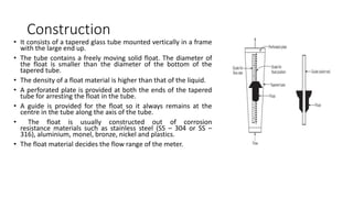
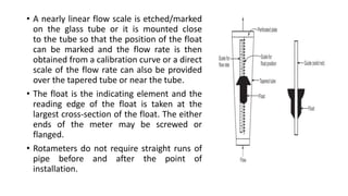
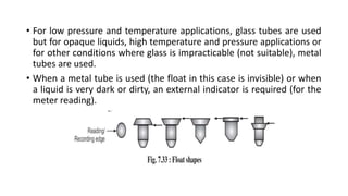
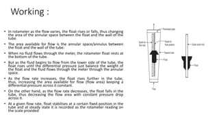
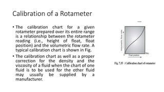
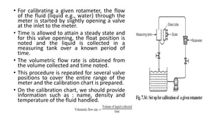
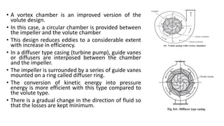
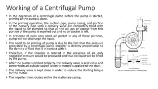
FLOW MEASUREMENTS &
MECHANICAL OPERATIONS
18BT33-MODULE 2
ROTAMETER
• In the orifice meter or venturi meter (variable head meters), the area
of constriction / area of flow is constant and the differential pressure
/ pressure drop across the meter varies with the flow rate / discharge,
while in the variable area meter, the pressure drop across the meter
is constant and the flow rate is a function of the area of constriction /
area of flow.
• Thus, any change in the flow rate can be measured in terms of the
change in the area of flow.
• The most important area meter is the rotameter.
Principle :
• Rotameter operates on the principle that there is a different
constriction / orifice area (flow area) for each flow rate and the
pressure drop across the meter is constant.
• In other words, the pressure drop across the meter is constant and
the area through which the fluid flows varies with the flow rate.
• This area is related, through a proper calibration, to the flow rate.
Construction
• It consists of a tapered glass tube mounted vertically in a frame
with the large end up.
• The tube contains a freely moving solid float. The diameter of
the float is smaller than the diameter of the bottom of the
tapered tube.
• The density of a float material is higher than that of the liquid.
• A perforated plate is provided at both the ends of the tapered
tube for arresting the float in the tube.
• A guide is provided for the float so it always remains at the
centre in the tube along the axis of the tube.
• The float is usually constructed out of corrosion
resistance materials such as stainless steel (SS – 304 or SS –
316), aluminium, monel, bronze, nickel and plastics.
• The float material decides the flow range of the meter.
• A nearly linear flow scale is etched/marked
on the glass tube or it is mounted close
to the tube so that the position of the float
can be marked and the flow rate is then
obtained from a calibration curve or a direct
scale of the flow rate can also be provided
over the tapered tube or near the tube.
• The float is the indicating element and the
reading edge of the float is taken at the
largest cross-section of the float. The either
ends of the meter may be screwed or
flanged.
• Rotameters do not require straight runs of
pipe before and after the point of
installation.
• For low pressure and temperature applications, glass tubes are used
but for opaque liquids, high temperature and pressure applications or
for other conditions where glass is impracticable (not suitable), metal
tubes are used.
• When a metal tube is used (the float in this case is invisible) or when
a liquid is very dark or dirty, an external indicator is required (for the
meter reading).
Working :
• In rotameter as the flow varies, the float rises or falls, thus changing
the area of the annular space between the float and the wall of the
tube.
• The area available for flow is the annular space/annulus between
the float and the wall of the tube.
• When no fluid flows through the meter, the rotameter float rests at
the bottom of the tube.
• But as the fluid begins to flow from the lower side of the tube, the
float rises until the differential pressure just balance the weight of
the float and the fluid flows through the meter through the annular
space.
• As the flow rate increases, the float rises further in the tube,
thus, increasing the area available for flow (flow area) keeping a
differential pressure across it constant.
• On the other hand, as the flow rate decreases, the float falls in the
tube, thus decreasing the flow area with constant pressure drop
across it.
• At a given flow rate, float stabilises at a certain fixed position in the
tube and at steady state it is recorded as the rotameter reading on
the scale provided
• The variation of the flow area with flow rate can be measured in
terms of change in the float position.
• A rotating motion of the float helps to keep it steady.
• Rotameters are widely used in the chemical industry for the
measurement of flow rates of compressible as well as incompressible
fluids.
• They provide a directing reading of the flow rate.
Calibration of a Rotameter
• The calibration chart for a given
rotameter prepared over its entire range
is a relationship between the rotameter
reading (i.e., height of float, float
position) and the volumetric flow rate. A
typical calibration chart is shown in Fig.
• The calibration chart as well as a proper
correction for the density and the
viscosity of a fluid when the chart of one
fluid is to be used for the other fluid
may usually be supplied by a
manufacturer.
• For calibrating a given rotameter, the flow
of the fluid (liquid e.g., water) through the
meter is started by slightly opening a valve
at the inlet to the meter.
• Time is allowed to attain a steady state and
for this valve opening, the float position is
noted and the liquid is collected in a
measuring tank over a known period of
time.
• The volumetric flow rate is obtained from
the volume collected and time noted.
• This procedure is repeated for several valve
positions to cover the entire range of the
meter and the calibration chart is prepared.
• On the calibration chart, we should provide
information such as : name, density and
temperature of the fluid handled.
PUMPING DEVICES FOR LIQUIDS
• A pump is a machine which converts mechanical energy supplied to it
from some external source into pressure energy which is used to lift a
liquid from a lower level to a higher level.
• A pump is a machine used for handling liquids, solution or slurries.
CLASSIFICATION OF PUMPS
• 1. Centrifugal pumps.
• 2. Positive displacement pumps.
• In centrifugal pumps, the kinetic energy of the liquid to be pumped is increased by
the action of centrifugal force and is then converted into pressure energy that is needed
to pump the liquid.
• In positive displacement pumps, a definite or fixed quantity of liquid is pumped in
every revolution. Since a fixed quantity of liquid is pumped after each revolution they can
develop a very high pressure if the delivery valve or line is closed.
• Positive displacement pumps are further classified as :
• 1. Reciprocating pumps, e.g., piston pump, plunger pump, etc.
• 2. Rotary pumps, e.g., gear pump, mono pump
• In reciprocating pumps, the displacement is by reciprocation of a piston or plunger,
while in rotary pumps, the displacement is by rotary action of a gear or vane.
Factors which influence the choice of pump for a
particular operation
• While selecting a pump for a particular duty we have to consider the
following factors :
• (i) The quantity of liquid to be handled.
• (ii) The head against which the liquid to be pumped/raised.
• (iii) The nature of liquid to be handled (viscosity, clear liquids, suspensions,
corrosive nature).
• (iv) The nature of power supply.
• (v) The method of operation – continuous or intermittent.
• (vi) The flow rate required.
• (vii) The pressure on delivery.
• (viii) Cost and mechanical efficiency
Measurement of performance
• (i) Capacity : It is the rate at which the fluid is pumped by a fluid
moving device.
• It is expressed in various units – based on the type of pumping device.
• For liquids, it is expressed in litres per minute or gallons per minute
and for gases, it is expressed in cubic feet per minute at inlet
conditions of gases to the machine.
• (ii) Overall efficiency : It is the ratio of the useful hydraulic work
performed to the actual work input, irrespective of the type of drive.
CENTRIFUGAL PUMPS
• A pump which lifts a liquid from a lower level to a higher level by the action
of a centrifugal force is called as a centrifugal pump.
• Centrifugal pumps are very widely used in the chemical and petroleum
industries because of its many advantages such as simplicity of design, low
initial cost, low maintenance and flexibility of operation.
• The centrifugal pump can handle liquids of a wide range of properties.
• It is equally suitable for handling suspensions with a high solid content.
• It may be constructed from a wide range of corrosion resistant materials
and it may be directly coupled to an electric motor as it operates at high
speeds.
• In a centrifugal pump, power from an outside
source is applied to the shaft, the impeller
then rotates within the stationary casing.
• The impeller blades in revolving produce a
reduction in pressure at the eye of the
impeller.
• Due to this, liquid flows into the impeller from
the suction pipe.
• The liquid is thrown outward by the centrifugal
action along the blades.
• As a result of high speed of rotation, the liquid
acquires a high kinetic energy.
• The kinetic energy acquired is then converted
into pressure energy when it leaves the blade
tips and the liquid passes into the volute
chamber and finally it is discharged through
the outlet (discharge) on the pump.
Construction or Component Parts of a
Centrifugal Pump
1. Impeller
• It is a wheel or rotor that is
provided with a series of curved
blades or vanes.
• It is mounted on a shaft which is
coupled to an electric motor (an
external source of energy).
• The blades/vanes are shaped in
such a way that the flow within
the pump is as smooth
as possible.
• The impeller is the heart of the
centrifugal pump.
• Impeller types :
• (i) Open impeller, (ii) Semi-open impeller, and (iii) Closed or shrouded
impeller.
• The open impeller has the blades fixed to a central hub. Such
impellers are suited for pumping liquids containing suspended solids,
e.g., paper pulp, sewage, etc.
• The closed impeller has the blades held between two supporting
plates / shrouds (crown plate and base plate). This impeller provides
better guidance for the liquid and is more efficient. This type of
impeller is suited for pumping clear liquids (liquids containing
no suspended particles, dirts, etc.).
• The semi-open impeller has only one plate (base plate) and no crown
plate (i.e., it has a plate on one side of the blades/vanes). Such
impellers are suitable for liquids containing some solid particles or
dirts.
• For viscous liquids or liquids containing solids, open or semi-open
type impellers are used.
• The most efficient impeller is the closed or shrouded type.
• The impeller may be a single suction type or double suction type. In
the former type, the liquid enters the impeller from one side; while in
the latter type, the liquid enters from both the sides.
casing
• It is an airtight chamber in which the impeller rotates.
• It is provided with an inlet (suction) and outlet
(discharge) for the liquid to be pumped.
• The function of the casing is to convert the kinetic
energy imparted to the liquid by the impeller into
useful pressure energy.
• Types of casing : (i) volute type casing and (ii) diffuser
type casing.
• In a volute type casing, the liquid is discharged by
the impeller into the volute – a chamber of gradually
increasing cross-sectional area towards the outlet .
• In the volute, the fluid velocity decreases gradually
thereby increasing fluid pressure, i.e., the volute
converts the kinetic energy of the liquid imparted by
the impeller into pressure energy.
• In this design, a considerable loss of energy takes place
due to formation of eddies.
• A vortex chamber is an improved version of the
volute design.
• In this case, a circular chamber is provided between
the impeller and the volute chamber
• This design reduces eddies to a considerable extent
with increase in efficiency.
• In a diffuser type casing (turbine pump), guide vanes
or diffusers are interposed between the chamber
and the impeller.
• The impeller is surrounded by a series of guide vanes
mounted on a ring called diffuser ring.
• The conversion of kinetic energy into pressure
energy is more efficient with this type compared to
the volute type.
• There is a gradual change in the direction of fluid so
that the losses are kept minimum.
• Other component parts of the centrifugal pump are : shaft, bearing,
stuffing box, or mechanical seal, etc.
• Shaft must be of a corrosion resistant material and must have
good mechanical properties.
• The shaft transmits power from the drive unit to the impeller.
• Sometimes, a shaft sleeve of corrosion resistant material is provided over
the corrosive shaft material from strength criteria.
• Shaft is mounted on bearings which handle shaft load without excessive
wear.
• Stuffing box is a means of reducing/avoiding leakage which would
otherwise occur at the point of entry of the shaft into the casing.
• With this the maintenance costs are high.
• A considerable reduction in expenditure on maintenance can be effected at
the price of a small increase in the initial cost by fitting the pump with a
mechanical seal. For high pressures and corrosive fluids, mechanical seals
are used.
Working of a Centrifugal Pump
• In the operation of a centrifugal pump before the pump is started,
priming of the pump is done.
• In the priming operation, the suction pipe, pump casing, and portion
of the delivery pipe upto a delivery valve are completely filled with
the liquid to be pumped so that all the air, gas or vapour from this
portion of the pump is expelled out and no air pocket is left.
• In presence of even very small air pocket in any of these portions,
pump will not discharge the liquid.
• The need to do priming of pump is due to the fact that the pressure
generated by a centrifugal pump impeller is directly proportional to
the density of fluid that is in contact with it.
• Therefore, if the impeller is rotated in the presence of air, only
negligible pressure would be produced and thus no liquid will be lifted
by the pump.
• After the pump is primed properly, the delivery valve is kept close and
power from an outside source (electric motor) is applied to the shaft.
• The delivery valve is kept close in order to reduce the starting torque
for the motor.
• The impeller then rotates within the stationary casing.
• The rotation of the impeller produces a forced vortex which imparts
a centrifugal head to the liquid and thus results in an increase of pressure
throughout the liquid mass.
• As long as the delivery valve is closed and impeller is rotated, there will be
just churning of the liquid within the casing.
• When the delivery valve is opened, the liquid is made to flow in an outward
radial direction thereby leaving the vanes of the impeller at the outer
circumference with high velocity and pressure.
• Due to centrifugal action, a partial vacuum is created at the eye of the
impeller.
• This causes the liquid from the sump/reservoir (at atmospheric pressure)
to flow through the suction pipe to the eye of the impeller
thereby replacing the liquid which is being discharged from the entire
circumference of the impeller.
• The high pressure of the liquid leaving the impeller is utilised in lifting the
liquid to the required height through the delivery pipe.
• During the operation, liquid receives energy from the vanes which
results in an increase in both pressure and velocity energy.
• As such the liquid leaves the impeller with a high absolute velocity.
Advantages of Centrifugal Pump :
• 1.It is simple in construction.
• 2. Due to its simplicity of construction, it can be made in a wide range of materials.
• 3. Low initial cost and simplicity of design.
• 4. It operates at high speed and hence, can be coupled directly to an electric motor. In
• general, higher the speed, smaller the pump and motor required for a given duty.
• 5. It gives a steady delivery / discharge.
• 6. Lower maintenance (compared to other pumps) costs.
• 7. It does not get damaged even if the delivery line becomes blocked, or the delivery
valve is closed, provided the pump does not run in this condition for a prolonged period.
• 8. It can handle readily liquids containing high proportions of suspended solids.
• 9. For equal capacity, the centrifugal pump is much smaller than any other type of pump.
Therefore, it can be made into a sealed unit with the driving motor and immersed in the
suction tank.
Disadvantages of Centrifugal Pump :
• 1. It is not usually self-priming.
• 2. It operates at low efficiencies (50 – 65%).
• 3. It cannot handle very viscous liquids efficiently.
• 4. It does not develop a high pressure. Multistage pumps will develop
greater pressure heads but they are much more expensive and
cannot be made into corrosion resistant materials because of their
greater complex construction.
• 5. If a non-return valve is not provided in the delivery or suction line,
the liquid will run back into the suction tank (reservoir) as soon as the
pump stops.
RECIPROCATING PUMPS
• Construction / Components of a Reciprocating Pump :
• A reciprocating pump essentially consists of a piston or plunger
which moves to and fro i.e., reciprocates back and forth in a close
fitting stationary cylinder.
• The cylinder is connected to suction and delivery pipes.
• Each of these pipes are provided with a non-return valve called
suction valve and delivery valve respectively.
• A non-return valve permits unidirectional flow.
• Thus, the suction valve allows the liquids only to enter the cylinder
and the delivery valve allows only its discharge from the cylinder.
• A piston or plunger is connected to a crank by means of a
connecting rod.
• The crank is rotated by a driving engine or electric motor. When the
crank is rotated by the drive, the piston or plunger moves to and
fro (forward and backward movement) in the cylinder.
The reciprocating pumps are provided with an air vessel at the
discharge
Working of a Reciprocating Pump :
• Assume that the piston or plunger is initially at its extremely left
position (i.e., completely inside the cylinder).
• If the crank rotates through 180o, then the piston or plunger moves
to its extreme right position (i.e., moves outwardly from the
cylinder).
• During the outward movement of the piston or plunger, a partial
vacuum is created in the cylinder, which enables the atmospheric
pressure acting on the liquid surface in the sump below to force the
liquid up the suction pipe and fill the cylinder by forcingly opening
the suction valve.
• As during this operation of the pump, the liquid is sucked from the
sump, it is known as a suction stroke.
• Hence, at the end of the suction stroke, the piston or plunger is at
its extreme right position, crank is at q = 180o, the cylinder is full of
liquid, the suction valve is closed and the delivery valve is just at the
point of opening
• When the crank rotates through further 180o (i.e., q =
180o to 360o), the piston or plunger moves inwardly
from its extreme right position towards left.
• The inward movement of the piston or plunger causes
the pressure of the liquid in the cylinder to rise
above atmospheric temperature, because of which
the suction valve closes and delivery valve opens.
• The liquid is then forced up the delivery pipe and
raised to the required height.
• As during this operation of the pump, the liquid is
actually delivered to the required height, it is known
as a delivery stroke.
• At the end of the delivery stroke, the piston or
plunger is at the extreme position, crank has one
complete revolution, and both the delivery and
suction valves are closed.
• The same cycle is repeated as the crank rotates.
• This is the working principle of a reciprocating pump
Types of Reciprocating Pumps
• Based on the reciprocating member (pressure component) piston,
plunger or diaphragm, there are three types of reciprocating pumps :
• 1. Piston pumps
• 2. Plunger pumps
• 3. Diaphragm pumps
• According to the liquid being in contact with one side or both the
sides of a piston or plunger, the reciprocating pumps may be classified
as :
• (i) Single acting pump and
• (ii) Double acting pump.
SIZE REDUCTION OF SOLIDS
CONCEPT OF SIZE REDUCTION
• Size reduction refers to an operation wherein particles of solids are
cut or broken into smaller pieces.
• Size reduction is a mechanical process of breakdown of solids into
smaller size particles without altering the state of aggregation of
solids. It is also called comminution.
• Solids are reduced in size by compression, impact, attrition and
cutting.
IMPORTANCE OF SIZE REDUCTION
• In the process industries, this operation is usually carried out in order –
• (i) to increase the surface in order to increase the rate of a physical or
chemical process. In most reactions and unit operations (e.g., leaching) involving
solid particles, the rate increases by increasing the area of contact between solid
and second phase since the rate is proportional to the area of contact between
the phases involved.
• In combustion process, the rate of combustion is proportional to the area
presented to the gas. Thus, the rate of combustion of solid particles is high if the
particles are of small size.
• In leaching, the rate of extraction increases because of the increased area of
contact between the solid and the solvent.
• (ii) to effect the separation of two constituents in cases where one is dispersed in
small isolated pockets.
• (iii) to meet stringent specifications regarding the size of commercial
products.
• (iv) to accomplish intimate mixing of solids in a solid-solid operation
since the mixing is more complete if the particle size is small.
• (v) to improve dissolution rate, solubility, binding strength and
dispersion properties.
• (vi) Many solid materials exist/present in sizes that are too large to be
used directly. Thus, such materials must be reduced in size before
use.
ENERGY & POWER REQUIREMENT FOR SIZE
REDUCTION EQUIPMENTS
• The cost of power is a major expense in the crushing and grinding operations.
Thus, an accurate estimation of the energy required is important in the design
and selection of size reduction equipment.
• During size reduction, the solid particles are first distorted and strained,
work required to strain them is stored temporarily in the solid particles as
mechanical energy of stress. By applying additional force, the stressed particles
are distorted beyond their ultimate strength and suddenly break into smaller
particles. Thus, new surface is generated.
• As a unit area of solid has a definite amount of surface energy, the generation of
new surface requires work, which is provided by the release of energy of stress
when the particles break. The energy of stress in excess of the new surface
energy created appears as heat.
• It is not possible to estimate accurately the power requirement of crushing
and grinding equipments to effect the size reduction of a given material, but a
number of empirical laws have been put forward, such as Rittinger's law, Kick's
law and Bond's law.
Ball Mill
• Principle :
• It works on the principle of impact, i.e., size reduction is
done by impact as the balls drop from near the top of
the shell.
• Construction :
• A ball mill consists of a hollow cylindrical shell rotating
about its axis. The axis of the shell may be either
horizontal or at a small angle to the horizontal. It is
partially filled with balls. The grinding medium is the
balls which may be made of steel, stainless steel or
rubber.
• The inner surface of the cylindrical shell is usually lined
with an abrasion-resistant material such as manganese
steel or rubber. The length of the mill is
approximately equal to its diameter
• The balls occupy about 30 to 50 percent
of the volume of the mill. The diameter
of ball used is/lies in between 12 mm
and 125 mm.
• The optimum diameter is approximately
proportional to the square root of the
size of the feed.
• The shell is rotated at low speed
through a drive gear (60-100 rpm) and
in a large ball mill, the shell might be 3
m in diameter and 4.25 m in length.
• The ball mill may be operated in a batch
or continuous fashion, wet or dry.
• In a continuously operated mill , the
outlet is normally covered with a coarse
screen to prevent the escape of the
balls.
• Working :
• In case of continuously operated ball mill, the
material to be ground is fed from the left through a
60o cone and the product is discharged through a
30o cone to the right.
• As the shell rotates, the balls are lifted up on the
rising side of the shell and then they cascade down
(or drop down on to the feed), from near the top of
the shell.
• In doing so, the solid particles in between the balls
are ground and reduced in size by impact.
• The mill contains balls of various ages and sizes
since the balls continually wear by attrition and are
replaced by new ones.
• As the shell rotates, the large balls segregate near
the feed end and small balls segregate near the
product end/discharge.
• The initial breaking of the feed particles is done by
the largest balls dropping from the largest distance
and small particles are ground by small balls
dropping from a much smaller distance.
• If the rate of feed is increased, a coarser product will be obtained and if the
speed of rotation is increased (less than critical speed), the fineness
for a given capacity increases.
• During grinding, balls themselves wear and are constantly replaced by new
ones so that mill contains balls of various ages and thus of various sizes.
• In case of batch operated mill, a known quantity of material to be ground
is charged into the mill through the opening in the shell.
• The opening is then closed and the mill is rotated for a predecided time. It
is then stopped and the product is discharged.
• Applications :
• The ball mill is used for grinding materials such as coal, pigments, and
felspar for pottery.
• Grinding can be carried out either wet or dry but the former is carried at
low speeds.
SIZE SEPARATION OF SOLIDS
• INTRODUCTION
• Solids may be separated from solids in the dry state by methods such as
screening (size separation-separation according to size), magnetic separation
and electrostatic separation.
• Screening :
• (i) A method of separating solid particles according to size alone is called
screening.
• (ii) Screening is an operation for separating solids on the basis of size alone.
• (iii) It refers to the separation of solid materials on the basis of size using
screens of known openings.
• (iv) Screening is the separation of a mixture of solid particles of various sizes
into two or more fractions by means of a screening surface.
Type of Screen Analysis
• There are two methods of reporting screen analysis : (1) Differential
analysis, (2) Cumulative analysis.
• Differential Analysis : The screen analysis in which the weight fraction
of the material retained on each screen is reported in a tabular or a
graphical form as a function of the mesh size/screen opening is called
differential analysis.
• Cumulative Analysis : The screen analysis in which the cumulative
weight fraction of the material retained (cumulative oversize) or
passing through (cumulative undersize) each screen is reported in a
tabular or a graphical form as a function of the screen opening is
called cumulative analysis
• The fine particles are generally specified according to their screen analysis.
• A screen analysis of a material is carried out by using testing sieves. A set of standard
screens is arranged serially in a stack in such a way that the coarsest of the screens is at
the top and the finest of the screens is at the bottom.
• An analysis is carried out by placing the sample on the top screen and shaking the stack
in a definite manner, either, manually or mechanically, for a definite length of time.
• The material retained on each screen is removed and weighed.
• For reporting the screen analysis, the amount of material retained on each screen
is expressed as the weight fraction of the total sample.
• The screen analysis of a sample is reported either in a tabular form or as graphs
• As the particles retained on any one screen are passed through the screen immediately
above it, two numbers are needed to specify the size, one for the screen through which
the fraction passes and the other for the screen on which that fraction is retained.
• Hence, the notation 10/14 means through 10 mesh and on 14 mesh (i.e., the material is
such that it passes through the screen of mesh number 10 and collects on the screen
of mesh number 14).
• An analysis reported in a tabular form in this manner is called a differential analysis.
• The material that is retained on the screen is
the oversize or plus (+) of that screen and
the material that passes it is the undersize or
minus (–). Thus, a – 10 + 14 fraction means
the fraction of the material that passes
through a 10-mesh screen but is retained on
a 14-mesh screen.
• The average particle size of the material
retained on any particular screen (cited
in Table 3.1) is calculated as the arithmetic
mean of two screen openings used to
obtain the fraction.
• The second method of
reporting screen analysis is
a cumulative analysis.
• The cumulative analysis is
obtained from the
differential analysis by
adding cumulatively, the
individual weight fractions
of material retained on
each screen, starting with
that retained on the
largest mesh, and
tabulating or plotting the
cumulative sums
against the screen opening
of the retaining screen
under consideration.
FILTRATION
• The separation of solids from a suspension in a liquid with the help of a porous medium or screen
which retains the solids and allows the liquid to pass is termed as filtration.
• The operation of separating a solid from a liquid by means of a porous medium (usually a wire or
fabric filter cloth) is called as filtration. The medium retains the solid in the form of a porous cake,
while the liquid passes through it.
• The mechanical separation of a solid from suspension in a liquid by passage through a porous
medium which retains the solid and allows the liquid to pass is called as filtration.
• In filtration operation, the volume of the suspensions to be handled may vary from extremely
large quantities (as in water purification) to relatively small quantities(as in the fine chemical
industry), the suspensions may contain small or large proportions of solids and the valuable
product may be the solid, the liquid, or both or sometimes none of them (e.g., the waste solids to
be separated from a waste liquid prior to the disposal).
• The driving force required for a separation by filtration based upon the nature of a suspension
may be divided into four categories, namely gravity, vacuum, pressure and centrifugal.
• Separation of suspended impurities from water (in water purification), separation of solid organic
and inorganic materials from their slurry such as calcium carbonate, ammonium sulphate, sugar,
paranitroaniline, etc. are some examples of filtration.
Types of Filtration : Cake Filtration and Deep
Bed Filtration
• Basically, there are two types of filtration.
• (i) Cake filtration, (ii) Deep bed filtration.
• In cake filtration, the proportion of solids in the suspension is large and most of the solid
particles are collected in the cake which can later be detached from the filter medium.
• In deep bed filtration, the proportion of solids is very small and the particles of the solid
being smaller than the pores of the filter medium will penetrate a considerable depth
and ultimately get trapped inside the filter medium and usually no layer of solids will
appear on the surface of the medium (e.g., water filtration).
• Thus, filters are divided into two main groups, clarifying filters and cake filters.
• Clarifying filters also called as deep bed filters are used to remove small amounts
of solids to produce sparkling clear liquids, whereas cake filters separate large
amounts of solids in the form of a cake of crystals.
• Clarifying filters find applications in water treatment.
Constant Rate and Constant Pressure Filtration
Types of filtration (based on the pressure drop across a filtering
medium) :
• There are two types of filtration :
• 1. Constant pressure filtration
• 2. Constant rate filtration.
• The method in which the pressure drop over the filter is held constant
throughout a run so that the rate of filtration is maximum at the start of
filtration and decreases continuously towards the end of the run is called
constant pressure filtration. If the outlet pressure is constant, constant
pressure filtration is carried out by applying a certain pressure at inlet and
maintaining it constant throughout the run.
• The method in which the pressure drop is varied usually from a minimum
at the start of filtration to a maximum at the end of filtration so that the
rate of filtration is constant throughout the run is called constant rate
filtration.
UO MODULE 2.pptx
UO MODULE 2.pptx
UO MODULE 2.pptx
UO MODULE 2.pptx

UO MODULE 2.pptx

  • 1.
    FLOW MEASUREMENTS & MECHANICALOPERATIONS 18BT33-MODULE 2
  • 2.
    ROTAMETER • In theorifice meter or venturi meter (variable head meters), the area of constriction / area of flow is constant and the differential pressure / pressure drop across the meter varies with the flow rate / discharge, while in the variable area meter, the pressure drop across the meter is constant and the flow rate is a function of the area of constriction / area of flow. • Thus, any change in the flow rate can be measured in terms of the change in the area of flow. • The most important area meter is the rotameter.
  • 3.
    Principle : • Rotameteroperates on the principle that there is a different constriction / orifice area (flow area) for each flow rate and the pressure drop across the meter is constant. • In other words, the pressure drop across the meter is constant and the area through which the fluid flows varies with the flow rate. • This area is related, through a proper calibration, to the flow rate.
  • 4.
    Construction • It consistsof a tapered glass tube mounted vertically in a frame with the large end up. • The tube contains a freely moving solid float. The diameter of the float is smaller than the diameter of the bottom of the tapered tube. • The density of a float material is higher than that of the liquid. • A perforated plate is provided at both the ends of the tapered tube for arresting the float in the tube. • A guide is provided for the float so it always remains at the centre in the tube along the axis of the tube. • The float is usually constructed out of corrosion resistance materials such as stainless steel (SS – 304 or SS – 316), aluminium, monel, bronze, nickel and plastics. • The float material decides the flow range of the meter.
  • 5.
    • A nearlylinear flow scale is etched/marked on the glass tube or it is mounted close to the tube so that the position of the float can be marked and the flow rate is then obtained from a calibration curve or a direct scale of the flow rate can also be provided over the tapered tube or near the tube. • The float is the indicating element and the reading edge of the float is taken at the largest cross-section of the float. The either ends of the meter may be screwed or flanged. • Rotameters do not require straight runs of pipe before and after the point of installation.
  • 6.
    • For lowpressure and temperature applications, glass tubes are used but for opaque liquids, high temperature and pressure applications or for other conditions where glass is impracticable (not suitable), metal tubes are used. • When a metal tube is used (the float in this case is invisible) or when a liquid is very dark or dirty, an external indicator is required (for the meter reading).
  • 7.
    Working : • Inrotameter as the flow varies, the float rises or falls, thus changing the area of the annular space between the float and the wall of the tube. • The area available for flow is the annular space/annulus between the float and the wall of the tube. • When no fluid flows through the meter, the rotameter float rests at the bottom of the tube. • But as the fluid begins to flow from the lower side of the tube, the float rises until the differential pressure just balance the weight of the float and the fluid flows through the meter through the annular space. • As the flow rate increases, the float rises further in the tube, thus, increasing the area available for flow (flow area) keeping a differential pressure across it constant. • On the other hand, as the flow rate decreases, the float falls in the tube, thus decreasing the flow area with constant pressure drop across it. • At a given flow rate, float stabilises at a certain fixed position in the tube and at steady state it is recorded as the rotameter reading on the scale provided
  • 8.
    • The variationof the flow area with flow rate can be measured in terms of change in the float position. • A rotating motion of the float helps to keep it steady. • Rotameters are widely used in the chemical industry for the measurement of flow rates of compressible as well as incompressible fluids. • They provide a directing reading of the flow rate.
  • 9.
    Calibration of aRotameter • The calibration chart for a given rotameter prepared over its entire range is a relationship between the rotameter reading (i.e., height of float, float position) and the volumetric flow rate. A typical calibration chart is shown in Fig. • The calibration chart as well as a proper correction for the density and the viscosity of a fluid when the chart of one fluid is to be used for the other fluid may usually be supplied by a manufacturer.
  • 10.
    • For calibratinga given rotameter, the flow of the fluid (liquid e.g., water) through the meter is started by slightly opening a valve at the inlet to the meter. • Time is allowed to attain a steady state and for this valve opening, the float position is noted and the liquid is collected in a measuring tank over a known period of time. • The volumetric flow rate is obtained from the volume collected and time noted. • This procedure is repeated for several valve positions to cover the entire range of the meter and the calibration chart is prepared. • On the calibration chart, we should provide information such as : name, density and temperature of the fluid handled.
  • 13.
    PUMPING DEVICES FORLIQUIDS • A pump is a machine which converts mechanical energy supplied to it from some external source into pressure energy which is used to lift a liquid from a lower level to a higher level. • A pump is a machine used for handling liquids, solution or slurries.
  • 14.
    CLASSIFICATION OF PUMPS •1. Centrifugal pumps. • 2. Positive displacement pumps. • In centrifugal pumps, the kinetic energy of the liquid to be pumped is increased by the action of centrifugal force and is then converted into pressure energy that is needed to pump the liquid. • In positive displacement pumps, a definite or fixed quantity of liquid is pumped in every revolution. Since a fixed quantity of liquid is pumped after each revolution they can develop a very high pressure if the delivery valve or line is closed. • Positive displacement pumps are further classified as : • 1. Reciprocating pumps, e.g., piston pump, plunger pump, etc. • 2. Rotary pumps, e.g., gear pump, mono pump • In reciprocating pumps, the displacement is by reciprocation of a piston or plunger, while in rotary pumps, the displacement is by rotary action of a gear or vane.
  • 15.
    Factors which influencethe choice of pump for a particular operation • While selecting a pump for a particular duty we have to consider the following factors : • (i) The quantity of liquid to be handled. • (ii) The head against which the liquid to be pumped/raised. • (iii) The nature of liquid to be handled (viscosity, clear liquids, suspensions, corrosive nature). • (iv) The nature of power supply. • (v) The method of operation – continuous or intermittent. • (vi) The flow rate required. • (vii) The pressure on delivery. • (viii) Cost and mechanical efficiency
  • 16.
    Measurement of performance •(i) Capacity : It is the rate at which the fluid is pumped by a fluid moving device. • It is expressed in various units – based on the type of pumping device. • For liquids, it is expressed in litres per minute or gallons per minute and for gases, it is expressed in cubic feet per minute at inlet conditions of gases to the machine. • (ii) Overall efficiency : It is the ratio of the useful hydraulic work performed to the actual work input, irrespective of the type of drive.
  • 17.
    CENTRIFUGAL PUMPS • Apump which lifts a liquid from a lower level to a higher level by the action of a centrifugal force is called as a centrifugal pump. • Centrifugal pumps are very widely used in the chemical and petroleum industries because of its many advantages such as simplicity of design, low initial cost, low maintenance and flexibility of operation. • The centrifugal pump can handle liquids of a wide range of properties. • It is equally suitable for handling suspensions with a high solid content. • It may be constructed from a wide range of corrosion resistant materials and it may be directly coupled to an electric motor as it operates at high speeds.
  • 18.
    • In acentrifugal pump, power from an outside source is applied to the shaft, the impeller then rotates within the stationary casing. • The impeller blades in revolving produce a reduction in pressure at the eye of the impeller. • Due to this, liquid flows into the impeller from the suction pipe. • The liquid is thrown outward by the centrifugal action along the blades. • As a result of high speed of rotation, the liquid acquires a high kinetic energy. • The kinetic energy acquired is then converted into pressure energy when it leaves the blade tips and the liquid passes into the volute chamber and finally it is discharged through the outlet (discharge) on the pump.
  • 19.
    Construction or ComponentParts of a Centrifugal Pump 1. Impeller • It is a wheel or rotor that is provided with a series of curved blades or vanes. • It is mounted on a shaft which is coupled to an electric motor (an external source of energy). • The blades/vanes are shaped in such a way that the flow within the pump is as smooth as possible. • The impeller is the heart of the centrifugal pump.
  • 20.
    • Impeller types: • (i) Open impeller, (ii) Semi-open impeller, and (iii) Closed or shrouded impeller. • The open impeller has the blades fixed to a central hub. Such impellers are suited for pumping liquids containing suspended solids, e.g., paper pulp, sewage, etc. • The closed impeller has the blades held between two supporting plates / shrouds (crown plate and base plate). This impeller provides better guidance for the liquid and is more efficient. This type of impeller is suited for pumping clear liquids (liquids containing no suspended particles, dirts, etc.). • The semi-open impeller has only one plate (base plate) and no crown plate (i.e., it has a plate on one side of the blades/vanes). Such impellers are suitable for liquids containing some solid particles or dirts. • For viscous liquids or liquids containing solids, open or semi-open type impellers are used. • The most efficient impeller is the closed or shrouded type. • The impeller may be a single suction type or double suction type. In the former type, the liquid enters the impeller from one side; while in the latter type, the liquid enters from both the sides.
  • 21.
    casing • It isan airtight chamber in which the impeller rotates. • It is provided with an inlet (suction) and outlet (discharge) for the liquid to be pumped. • The function of the casing is to convert the kinetic energy imparted to the liquid by the impeller into useful pressure energy. • Types of casing : (i) volute type casing and (ii) diffuser type casing. • In a volute type casing, the liquid is discharged by the impeller into the volute – a chamber of gradually increasing cross-sectional area towards the outlet . • In the volute, the fluid velocity decreases gradually thereby increasing fluid pressure, i.e., the volute converts the kinetic energy of the liquid imparted by the impeller into pressure energy. • In this design, a considerable loss of energy takes place due to formation of eddies.
  • 22.
    • A vortexchamber is an improved version of the volute design. • In this case, a circular chamber is provided between the impeller and the volute chamber • This design reduces eddies to a considerable extent with increase in efficiency. • In a diffuser type casing (turbine pump), guide vanes or diffusers are interposed between the chamber and the impeller. • The impeller is surrounded by a series of guide vanes mounted on a ring called diffuser ring. • The conversion of kinetic energy into pressure energy is more efficient with this type compared to the volute type. • There is a gradual change in the direction of fluid so that the losses are kept minimum.
  • 23.
    • Other componentparts of the centrifugal pump are : shaft, bearing, stuffing box, or mechanical seal, etc. • Shaft must be of a corrosion resistant material and must have good mechanical properties. • The shaft transmits power from the drive unit to the impeller. • Sometimes, a shaft sleeve of corrosion resistant material is provided over the corrosive shaft material from strength criteria. • Shaft is mounted on bearings which handle shaft load without excessive wear. • Stuffing box is a means of reducing/avoiding leakage which would otherwise occur at the point of entry of the shaft into the casing. • With this the maintenance costs are high. • A considerable reduction in expenditure on maintenance can be effected at the price of a small increase in the initial cost by fitting the pump with a mechanical seal. For high pressures and corrosive fluids, mechanical seals are used.
  • 24.
    Working of aCentrifugal Pump • In the operation of a centrifugal pump before the pump is started, priming of the pump is done. • In the priming operation, the suction pipe, pump casing, and portion of the delivery pipe upto a delivery valve are completely filled with the liquid to be pumped so that all the air, gas or vapour from this portion of the pump is expelled out and no air pocket is left. • In presence of even very small air pocket in any of these portions, pump will not discharge the liquid. • The need to do priming of pump is due to the fact that the pressure generated by a centrifugal pump impeller is directly proportional to the density of fluid that is in contact with it. • Therefore, if the impeller is rotated in the presence of air, only negligible pressure would be produced and thus no liquid will be lifted by the pump. • After the pump is primed properly, the delivery valve is kept close and power from an outside source (electric motor) is applied to the shaft. • The delivery valve is kept close in order to reduce the starting torque for the motor. • The impeller then rotates within the stationary casing.
  • 25.
    • The rotationof the impeller produces a forced vortex which imparts a centrifugal head to the liquid and thus results in an increase of pressure throughout the liquid mass. • As long as the delivery valve is closed and impeller is rotated, there will be just churning of the liquid within the casing. • When the delivery valve is opened, the liquid is made to flow in an outward radial direction thereby leaving the vanes of the impeller at the outer circumference with high velocity and pressure. • Due to centrifugal action, a partial vacuum is created at the eye of the impeller. • This causes the liquid from the sump/reservoir (at atmospheric pressure) to flow through the suction pipe to the eye of the impeller thereby replacing the liquid which is being discharged from the entire circumference of the impeller. • The high pressure of the liquid leaving the impeller is utilised in lifting the liquid to the required height through the delivery pipe.
  • 26.
    • During theoperation, liquid receives energy from the vanes which results in an increase in both pressure and velocity energy. • As such the liquid leaves the impeller with a high absolute velocity.
  • 27.
    Advantages of CentrifugalPump : • 1.It is simple in construction. • 2. Due to its simplicity of construction, it can be made in a wide range of materials. • 3. Low initial cost and simplicity of design. • 4. It operates at high speed and hence, can be coupled directly to an electric motor. In • general, higher the speed, smaller the pump and motor required for a given duty. • 5. It gives a steady delivery / discharge. • 6. Lower maintenance (compared to other pumps) costs. • 7. It does not get damaged even if the delivery line becomes blocked, or the delivery valve is closed, provided the pump does not run in this condition for a prolonged period. • 8. It can handle readily liquids containing high proportions of suspended solids. • 9. For equal capacity, the centrifugal pump is much smaller than any other type of pump. Therefore, it can be made into a sealed unit with the driving motor and immersed in the suction tank.
  • 28.
    Disadvantages of CentrifugalPump : • 1. It is not usually self-priming. • 2. It operates at low efficiencies (50 – 65%). • 3. It cannot handle very viscous liquids efficiently. • 4. It does not develop a high pressure. Multistage pumps will develop greater pressure heads but they are much more expensive and cannot be made into corrosion resistant materials because of their greater complex construction. • 5. If a non-return valve is not provided in the delivery or suction line, the liquid will run back into the suction tank (reservoir) as soon as the pump stops.
  • 29.
    RECIPROCATING PUMPS • Construction/ Components of a Reciprocating Pump : • A reciprocating pump essentially consists of a piston or plunger which moves to and fro i.e., reciprocates back and forth in a close fitting stationary cylinder. • The cylinder is connected to suction and delivery pipes. • Each of these pipes are provided with a non-return valve called suction valve and delivery valve respectively. • A non-return valve permits unidirectional flow. • Thus, the suction valve allows the liquids only to enter the cylinder and the delivery valve allows only its discharge from the cylinder. • A piston or plunger is connected to a crank by means of a connecting rod. • The crank is rotated by a driving engine or electric motor. When the crank is rotated by the drive, the piston or plunger moves to and fro (forward and backward movement) in the cylinder. The reciprocating pumps are provided with an air vessel at the discharge
  • 30.
    Working of aReciprocating Pump : • Assume that the piston or plunger is initially at its extremely left position (i.e., completely inside the cylinder). • If the crank rotates through 180o, then the piston or plunger moves to its extreme right position (i.e., moves outwardly from the cylinder). • During the outward movement of the piston or plunger, a partial vacuum is created in the cylinder, which enables the atmospheric pressure acting on the liquid surface in the sump below to force the liquid up the suction pipe and fill the cylinder by forcingly opening the suction valve. • As during this operation of the pump, the liquid is sucked from the sump, it is known as a suction stroke. • Hence, at the end of the suction stroke, the piston or plunger is at its extreme right position, crank is at q = 180o, the cylinder is full of liquid, the suction valve is closed and the delivery valve is just at the point of opening
  • 31.
    • When thecrank rotates through further 180o (i.e., q = 180o to 360o), the piston or plunger moves inwardly from its extreme right position towards left. • The inward movement of the piston or plunger causes the pressure of the liquid in the cylinder to rise above atmospheric temperature, because of which the suction valve closes and delivery valve opens. • The liquid is then forced up the delivery pipe and raised to the required height. • As during this operation of the pump, the liquid is actually delivered to the required height, it is known as a delivery stroke. • At the end of the delivery stroke, the piston or plunger is at the extreme position, crank has one complete revolution, and both the delivery and suction valves are closed. • The same cycle is repeated as the crank rotates. • This is the working principle of a reciprocating pump
  • 32.
    Types of ReciprocatingPumps • Based on the reciprocating member (pressure component) piston, plunger or diaphragm, there are three types of reciprocating pumps : • 1. Piston pumps • 2. Plunger pumps • 3. Diaphragm pumps • According to the liquid being in contact with one side or both the sides of a piston or plunger, the reciprocating pumps may be classified as : • (i) Single acting pump and • (ii) Double acting pump.
  • 33.
    SIZE REDUCTION OFSOLIDS CONCEPT OF SIZE REDUCTION • Size reduction refers to an operation wherein particles of solids are cut or broken into smaller pieces. • Size reduction is a mechanical process of breakdown of solids into smaller size particles without altering the state of aggregation of solids. It is also called comminution. • Solids are reduced in size by compression, impact, attrition and cutting.
  • 34.
    IMPORTANCE OF SIZEREDUCTION • In the process industries, this operation is usually carried out in order – • (i) to increase the surface in order to increase the rate of a physical or chemical process. In most reactions and unit operations (e.g., leaching) involving solid particles, the rate increases by increasing the area of contact between solid and second phase since the rate is proportional to the area of contact between the phases involved. • In combustion process, the rate of combustion is proportional to the area presented to the gas. Thus, the rate of combustion of solid particles is high if the particles are of small size. • In leaching, the rate of extraction increases because of the increased area of contact between the solid and the solvent. • (ii) to effect the separation of two constituents in cases where one is dispersed in small isolated pockets.
  • 35.
    • (iii) tomeet stringent specifications regarding the size of commercial products. • (iv) to accomplish intimate mixing of solids in a solid-solid operation since the mixing is more complete if the particle size is small. • (v) to improve dissolution rate, solubility, binding strength and dispersion properties. • (vi) Many solid materials exist/present in sizes that are too large to be used directly. Thus, such materials must be reduced in size before use.
  • 36.
    ENERGY & POWERREQUIREMENT FOR SIZE REDUCTION EQUIPMENTS • The cost of power is a major expense in the crushing and grinding operations. Thus, an accurate estimation of the energy required is important in the design and selection of size reduction equipment. • During size reduction, the solid particles are first distorted and strained, work required to strain them is stored temporarily in the solid particles as mechanical energy of stress. By applying additional force, the stressed particles are distorted beyond their ultimate strength and suddenly break into smaller particles. Thus, new surface is generated. • As a unit area of solid has a definite amount of surface energy, the generation of new surface requires work, which is provided by the release of energy of stress when the particles break. The energy of stress in excess of the new surface energy created appears as heat. • It is not possible to estimate accurately the power requirement of crushing and grinding equipments to effect the size reduction of a given material, but a number of empirical laws have been put forward, such as Rittinger's law, Kick's law and Bond's law.
  • 39.
    Ball Mill • Principle: • It works on the principle of impact, i.e., size reduction is done by impact as the balls drop from near the top of the shell. • Construction : • A ball mill consists of a hollow cylindrical shell rotating about its axis. The axis of the shell may be either horizontal or at a small angle to the horizontal. It is partially filled with balls. The grinding medium is the balls which may be made of steel, stainless steel or rubber. • The inner surface of the cylindrical shell is usually lined with an abrasion-resistant material such as manganese steel or rubber. The length of the mill is approximately equal to its diameter
  • 40.
    • The ballsoccupy about 30 to 50 percent of the volume of the mill. The diameter of ball used is/lies in between 12 mm and 125 mm. • The optimum diameter is approximately proportional to the square root of the size of the feed. • The shell is rotated at low speed through a drive gear (60-100 rpm) and in a large ball mill, the shell might be 3 m in diameter and 4.25 m in length. • The ball mill may be operated in a batch or continuous fashion, wet or dry. • In a continuously operated mill , the outlet is normally covered with a coarse screen to prevent the escape of the balls.
  • 41.
    • Working : •In case of continuously operated ball mill, the material to be ground is fed from the left through a 60o cone and the product is discharged through a 30o cone to the right. • As the shell rotates, the balls are lifted up on the rising side of the shell and then they cascade down (or drop down on to the feed), from near the top of the shell. • In doing so, the solid particles in between the balls are ground and reduced in size by impact. • The mill contains balls of various ages and sizes since the balls continually wear by attrition and are replaced by new ones. • As the shell rotates, the large balls segregate near the feed end and small balls segregate near the product end/discharge. • The initial breaking of the feed particles is done by the largest balls dropping from the largest distance and small particles are ground by small balls dropping from a much smaller distance.
  • 42.
    • If therate of feed is increased, a coarser product will be obtained and if the speed of rotation is increased (less than critical speed), the fineness for a given capacity increases. • During grinding, balls themselves wear and are constantly replaced by new ones so that mill contains balls of various ages and thus of various sizes. • In case of batch operated mill, a known quantity of material to be ground is charged into the mill through the opening in the shell. • The opening is then closed and the mill is rotated for a predecided time. It is then stopped and the product is discharged. • Applications : • The ball mill is used for grinding materials such as coal, pigments, and felspar for pottery. • Grinding can be carried out either wet or dry but the former is carried at low speeds.
  • 43.
    SIZE SEPARATION OFSOLIDS • INTRODUCTION • Solids may be separated from solids in the dry state by methods such as screening (size separation-separation according to size), magnetic separation and electrostatic separation. • Screening : • (i) A method of separating solid particles according to size alone is called screening. • (ii) Screening is an operation for separating solids on the basis of size alone. • (iii) It refers to the separation of solid materials on the basis of size using screens of known openings. • (iv) Screening is the separation of a mixture of solid particles of various sizes into two or more fractions by means of a screening surface.
  • 44.
    Type of ScreenAnalysis • There are two methods of reporting screen analysis : (1) Differential analysis, (2) Cumulative analysis. • Differential Analysis : The screen analysis in which the weight fraction of the material retained on each screen is reported in a tabular or a graphical form as a function of the mesh size/screen opening is called differential analysis. • Cumulative Analysis : The screen analysis in which the cumulative weight fraction of the material retained (cumulative oversize) or passing through (cumulative undersize) each screen is reported in a tabular or a graphical form as a function of the screen opening is called cumulative analysis
  • 45.
    • The fineparticles are generally specified according to their screen analysis. • A screen analysis of a material is carried out by using testing sieves. A set of standard screens is arranged serially in a stack in such a way that the coarsest of the screens is at the top and the finest of the screens is at the bottom. • An analysis is carried out by placing the sample on the top screen and shaking the stack in a definite manner, either, manually or mechanically, for a definite length of time. • The material retained on each screen is removed and weighed. • For reporting the screen analysis, the amount of material retained on each screen is expressed as the weight fraction of the total sample. • The screen analysis of a sample is reported either in a tabular form or as graphs • As the particles retained on any one screen are passed through the screen immediately above it, two numbers are needed to specify the size, one for the screen through which the fraction passes and the other for the screen on which that fraction is retained. • Hence, the notation 10/14 means through 10 mesh and on 14 mesh (i.e., the material is such that it passes through the screen of mesh number 10 and collects on the screen of mesh number 14). • An analysis reported in a tabular form in this manner is called a differential analysis.
  • 46.
    • The materialthat is retained on the screen is the oversize or plus (+) of that screen and the material that passes it is the undersize or minus (–). Thus, a – 10 + 14 fraction means the fraction of the material that passes through a 10-mesh screen but is retained on a 14-mesh screen. • The average particle size of the material retained on any particular screen (cited in Table 3.1) is calculated as the arithmetic mean of two screen openings used to obtain the fraction.
  • 47.
    • The secondmethod of reporting screen analysis is a cumulative analysis. • The cumulative analysis is obtained from the differential analysis by adding cumulatively, the individual weight fractions of material retained on each screen, starting with that retained on the largest mesh, and tabulating or plotting the cumulative sums against the screen opening of the retaining screen under consideration.
  • 49.
    FILTRATION • The separationof solids from a suspension in a liquid with the help of a porous medium or screen which retains the solids and allows the liquid to pass is termed as filtration. • The operation of separating a solid from a liquid by means of a porous medium (usually a wire or fabric filter cloth) is called as filtration. The medium retains the solid in the form of a porous cake, while the liquid passes through it. • The mechanical separation of a solid from suspension in a liquid by passage through a porous medium which retains the solid and allows the liquid to pass is called as filtration. • In filtration operation, the volume of the suspensions to be handled may vary from extremely large quantities (as in water purification) to relatively small quantities(as in the fine chemical industry), the suspensions may contain small or large proportions of solids and the valuable product may be the solid, the liquid, or both or sometimes none of them (e.g., the waste solids to be separated from a waste liquid prior to the disposal). • The driving force required for a separation by filtration based upon the nature of a suspension may be divided into four categories, namely gravity, vacuum, pressure and centrifugal. • Separation of suspended impurities from water (in water purification), separation of solid organic and inorganic materials from their slurry such as calcium carbonate, ammonium sulphate, sugar, paranitroaniline, etc. are some examples of filtration.
  • 50.
    Types of Filtration: Cake Filtration and Deep Bed Filtration • Basically, there are two types of filtration. • (i) Cake filtration, (ii) Deep bed filtration. • In cake filtration, the proportion of solids in the suspension is large and most of the solid particles are collected in the cake which can later be detached from the filter medium. • In deep bed filtration, the proportion of solids is very small and the particles of the solid being smaller than the pores of the filter medium will penetrate a considerable depth and ultimately get trapped inside the filter medium and usually no layer of solids will appear on the surface of the medium (e.g., water filtration). • Thus, filters are divided into two main groups, clarifying filters and cake filters. • Clarifying filters also called as deep bed filters are used to remove small amounts of solids to produce sparkling clear liquids, whereas cake filters separate large amounts of solids in the form of a cake of crystals. • Clarifying filters find applications in water treatment.
  • 51.
    Constant Rate andConstant Pressure Filtration Types of filtration (based on the pressure drop across a filtering medium) : • There are two types of filtration : • 1. Constant pressure filtration • 2. Constant rate filtration. • The method in which the pressure drop over the filter is held constant throughout a run so that the rate of filtration is maximum at the start of filtration and decreases continuously towards the end of the run is called constant pressure filtration. If the outlet pressure is constant, constant pressure filtration is carried out by applying a certain pressure at inlet and maintaining it constant throughout the run. • The method in which the pressure drop is varied usually from a minimum at the start of filtration to a maximum at the end of filtration so that the rate of filtration is constant throughout the run is called constant rate filtration.