Unit Operations: Introduction
UnitOperations: Introduction
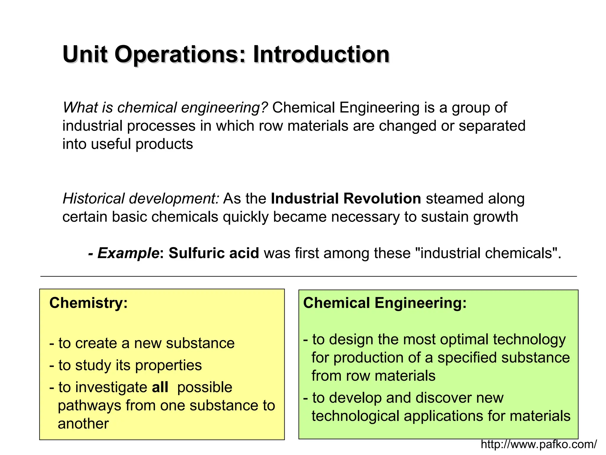
What is chemical engineering? Chemical Engineering is a group of
industrial processes in which row materials are changed or separated
into useful products
Historical development: As the Industrial Revolution steamed along
certain basic chemicals quickly became necessary to sustain growth
- Example: Sulfuric acid was first among these "industrial chemicals".
http://www.pafko.com/
Chemistry:
- to create a new substance
- to study its properties
- to investigate all possible
pathways from one substance to
another
Chemical Engineering:
- to design the most optimal technology
for production of a specified substance
from row materials
- to develop and discover new
technological applications for materials
Comparison of twoprocesses
Comparison of two processes
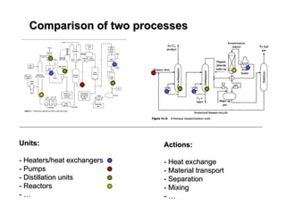
Units:
Units:
- Heaters/heat exchangers
- Heaters/heat exchangers
- Pumps
- Pumps
- Distillation units
- Distillation units
- Reactors
- Reactors
- …
- …
Actions:
Actions:
- Heat exchange
- Heat exchange
- Material transport
- Material transport
- Separation
- Separation
- Mixing
- Mixing
- …
- …
5.
Unit Operations:
Unit Operations:
-Unit Operations is a method of analysis and design of chemical
engineering processes in terms of individual tasks/operations
- It is a way of organizing chemical engineering knowledge into
groups of individual tasks/operations
- A unit operation: basic step in a chemical engineering process
Section Lectures Tutorial
1.Introduction, revision,
binary distillation with non-
constant molar overflow
2. Separation of
multicomponent mixtures
3. Separations in packed
columns. Absorption
4. Adsorption processes
5. Humidification processes
6. Drying processes
7. Revision and problems
1.1 Introduction to Unit Operations;
Equilibrium stage operations (L1)
1.2 Thermodynamics of distillation (L2)
1.3 Binary distillations review (L3)
2.1 Multicomponent Distillation: Flash
distillation (L4)
2.2 Multicomponent Distillation: Short
Cut Methods (L5)
2.3 Multicomponent Distillation: Short
Cut Methods (L6)
3.1 Mass transport theories review (L7)
3.2 Mass transport theories review (L8)
3.3 Packed bed columns (L9)
3.4 Packed bed columns (L10)
4.1 Principles of adsorption (L11)
4.2 Principles of adsorption (L12)
5.1 Principles of humidification (L13)
5.2 Methods of humidification (L14)
6.1 Principles of drying (L15)
6.2 Methods of drying (L16)
7.1 Revision (L17)
7.2 Revision (L18)
http://www.see.ed.ac.uk/~lsarkiso/UnitOps/syllabus.htm
8.
Total 18 lecturesand at least 6 tutorials
Tutorials We will have a number of tutorials
focusing on specific examples of unit
operations.
Assessment Unit operations 1.5h exam. 2
questions
Text books 1) Warren L. McCabe, Julian C. Smith and
Peter Harriot, Unit Operations
of Chemical Engineering,
(Seventh Edition). McGrawHill, 2005.
2) Robert E. Treybal, Mass Transfer
Operations (McGraw-Hill Classic
Textbook Reissue Series) (Paperback)
3) J.D. Seader and Ernest J. Henley,
Separation Process Principles, John Wiley
& Sons, 1998.
9.
Chemical separation processes:
Chemicalseparation processes:
required background
required background
B
B
V
V
D
D
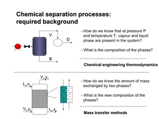
- How do we know that at pressure P
and temperature T, vapour and liquid
phase are present in the system?
- What is the composition of the phases?
Chemical engineering thermodynamics
Chemical engineering thermodynamics
La,xa
Va,ya
Vb,yb Lb,xb
- How do we know the amount of mass
exchanged by two phases?
- What is the new composition of the
phases?
Mass transfer methods
Mass transfer methods
10.
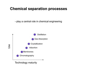
Chemical separation processes
Chemicalseparation processes
- play a central role in chemical engineering
Use
Technology maturity
Distillation
Gas Absorption
Crystallization
Adsortion
Membranes
Chromatography
11.
Chemical separation processes
Chemicalseparation processes
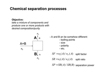
Objective:
take a mixture of components and
produce one or more products with
desired composition/purity
A+B
A B
B A
- A and B an be somehow different:
- boiling points
- size
- polarity
- etc.
)
(
/
)
(
1 A
n
A
n
SF F
nF
n1
n2 )
(
/
)
( 2
1 A
n
A
n
SR
split factor
split ratio
)
(
/
)
( B
SR
A
SR
SP separation power
12.
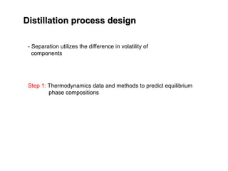
Distillation process design
Distillationprocess design
Step 1: Thermodynamics data and methods to predict equilibrium
phase compositions
- Separation utilizes the difference in volatility of
components
13.
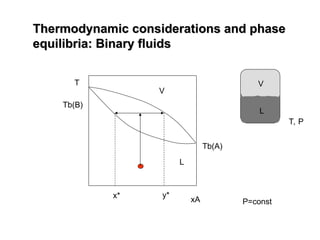
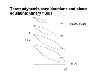
Thermodynamic considerations andphase
Thermodynamic considerations and phase
equilibria: Binary fluids
equilibria: Binary fluids
T
xA
Tb(B)
Tb(A)
V
L
y*
x*
T, P
V
L
14.
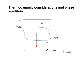
Thermodynamic considerations andphase
Thermodynamic considerations and phase
equilibria: Binary fluids
equilibria: Binary fluids
T
xA
Tb(B)
Tb(A)
V
L
y*
x*
T, P
V
L
P=const
15.
Thermodynamic considerations andphase
Thermodynamic considerations and phase
equilibria
equilibria
T
xA
Tb(B)
Tb(A)
V
L
y*
x*
P=const
16.
Thermodynamic considerations andphase
Thermodynamic considerations and phase
equilibria
equilibria
T
xA
Tb(B)
Tb(A)
V
L
y*
x*
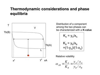
KA = yA/xA
KB = yB/xB
=(1-yA)/(1-xA)
Distribution of a component
among the two phases can
be characterized with a K-value
B
B
A
A
B
A
AB
x
y
x
y
K
K
/
/
Relative volatility
17.
Thermodynamic considerations andphase
Thermodynamic considerations and phase
equilibria: Binary fluids
equilibria: Binary fluids
T
xA
Tb(B)
Tb(A)
V
L
T1
T2
T3
T4
x1 y1
x2 y2
x3 y3
x4 y4
yA
xA
T1
T2
T3
T4
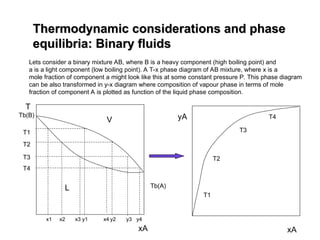
Lets consider a binary mixture AB, where B is a heavy component (high boiling point) and
a is a light component (low boiling point). A T-x phase diagram of AB mixture, where x is a
mole fraction of component a might look like this at some constant pressure P. This phase diagram
can be also transformed in y-x diagram where composition of vapour phase in terms of mole
fraction of component A is plotted as function of the liquid phase composition.
18.
Thermodynamic considerations andphase
Thermodynamic considerations and phase
equilibria: Binary fluids
equilibria: Binary fluids
T
xA
Tb(B)
Tb(A)
P1
P3
P2
P4 P1<P2<P3<P4
19.
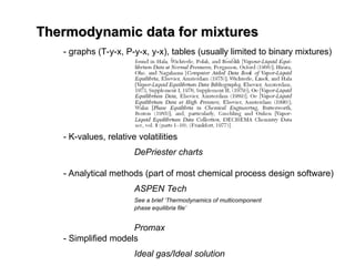
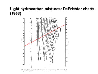
Thermodynamic data formixtures
Thermodynamic data for mixtures
- graphs (T-y-x, P-y-x, y-x), tables (usually limited to binary mixtures)
- K-values, relative volatilities
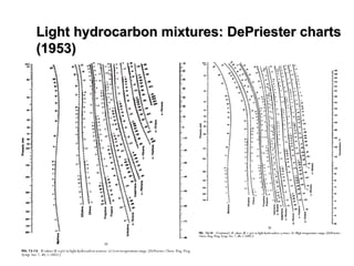
DePriester charts
- Analytical methods (part of most chemical process design software)
ASPEN Tech
See a brief ‘Thermodynamics of multicomponent
phase equilibria file’
Promax
- Simplified models
Ideal gas/Ideal solution
20.
Thermodynamic considerations andphase
Thermodynamic considerations and phase
equilibria: multicomponent mixtures
equilibria: multicomponent mixtures
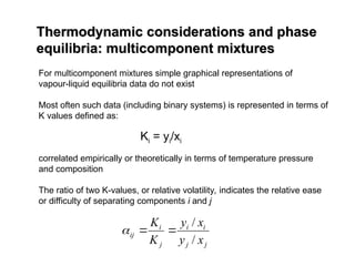
For multicomponent mixtures simple graphical representations of
vapour-liquid equilibria data do not exist
Most often such data (including binary systems) is represented in terms of
K values defined as:
correlated empirically or theoretically in terms of temperature pressure
and composition
The ratio of two K-values, or relative volatility, indicates the relative ease
or difficulty of separating components i and j
Ki = yi/xi
j
j
i
i
j
i
ij
x
y
x
y
K
K
/
/
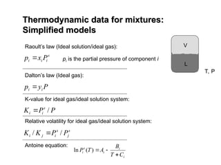
Thermodynamic data formixtures:
Thermodynamic data for mixtures:
Simplified models
Simplified models
Raoult’s law (Ideal solution/ideal gas):
s
i
i
i P
x
p pi is the partial pressure of component i
Dalton’s law (Ideal gas):
P
y
p i
i
K-value for ideal gas/ideal solution system:
P
P
K s
i
i /
Relative volatility for ideal gas/ideal solution system:
s
j
s
i
j
i P
P
K
K /
/
Antoine equation:
i
i
i
s
i
C
T
B
A
T
P
)
(
ln
T, P
V
L
24.
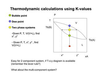
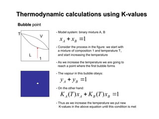
Thermodynamic calculations usingK-values
Thermodynamic calculations using K-values
Bubble
Bubble point
point
Dew point
Dew point
Two phase systems
Two phase systems
-Given P, T, V/(V+L), find
Given P, T, V/(V+L), find
x*, y*
x*, y*
- Given P, T, x*, y* , find
Given P, T, x*, y* , find
V/(V+L)
V/(V+L)
T
xA
Tb(B)
Tb(A)
V
L
y*
x*
P
Easy for 2 component system, if T-x-y diagram is available
(remember the lever rule?)
What about the multi-component system?
25.
Thermodynamic calculations usingK-values
Thermodynamic calculations using K-values
Bubble
Bubble point
point
T
V
L
- Model system: binary mixture A, B
- Consider the process in the figure: we start with
a mixture of composition 1 and temperature T1
and start increasing the temperature
- As we increase the temperature we are going to
reach a point where the first bubble forms
- The vapour in this bubble obeys:
- On the other hand:
- Thus as we increase the temperature we put new
K-values in the above equation until this condition is met
1
B
A x
x
1
B
A y
y
1
)
(
)
(
B
B
A
A x
T
K
x
T
K
1
26.
Thermodynamic calculations usingK-values
Thermodynamic calculations using K-values
Bubble point
Bubble point
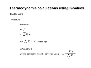
Procedure:
a) Select T
b) Ki(T)
c)
d) if T is too high
e) Adjusting T
g) Final composition can be corrected using
i
i
i x
K
1
i
i
i x
K
i
i
i
i
i
i
x
K
x
K
y
27.
Thermodynamic calculations usingK-values
Thermodynamic calculations using K-values
Dew
Dew point
point
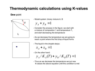
- Model system: binary mixture A, B
- Consider the process in the figure: we start with
a mixture of composition 1 and temperature T1
and start decreasing the temperature
- As we decrease the temperature we are going to
reach a point where the first drop of liquid forms
- The liquid in the droplet obeys:
- On the other hand:
- Thus as we decrease the temperature we put new
K-values the above equation until this condition is met
1
B
A y
y
1
B
A x
x
1
)
(
/
)
(
/
T
K
y
T
K
y B
B
A
A
T
V
L
1
28.
Thermodynamic calculations usingK-values
Thermodynamic calculations using K-values
Procedure:
a) Select T
b) Ki(T)
c)
d) if T is too low
e) Adjusting T
g) Final composition can be corrected using
i i
i
K
y
i
i
i
i
i
i
K
y
K
y
x
/
/
1
i i
i
K
y
Dew
Dew point
point
29.
Two phase system
Twophase system
F
i
z
1
1,T
P
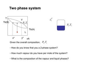
Given the overall composition,
- How do you know that you a 2-phase system?
- How much vapour do you have per mole of the system?
- What is the composition of the vapour and liquid phases?
T
xA
Tb(B)
Tb(A)
V
L
y*
x*
1
1,T
P
1
1,T
P
30.
B
i h
x
B ,
,
D
ih
y
D ,
,
F
F
i h
z
F ,
,
1
1,T
P
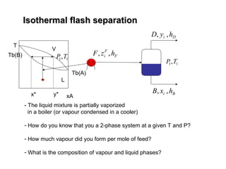
- The liquid mixture is partially vaporized
in a boiler (or vapour condensed in a cooler)
- How do you know that you a 2-phase system at a given T and P?
- How much vapour did you form per mole of feed?
- What is the composition of vapour and liquid phases?
T
xA
Tb(B)
Tb(A)
V
L
y*
x*
1
1,T
P
Isothermal flash separation
Isothermal flash separation
31.
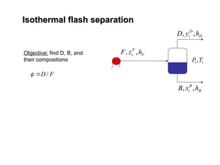
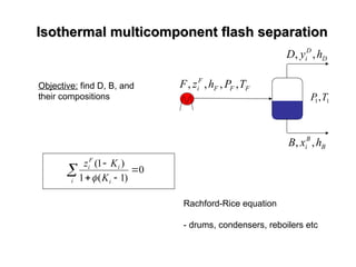
Isothermal flash separation
Isothermalflash separation
D
D
i h
y
D ,
,
F
F
i h
z
F ,
,
1
1,T
P
Objective: find D, B, and
their compositions
B
B
i h
x
B ,
,
F
D /
32.
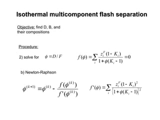
Isothermal multicomponent flashseparation
Isothermal multicomponent flash separation
D
D
i h
y
D ,
,
F
F
F
F
i T
P
h
z
F ,
,
,
,
1
1,T
P
Objective: find D, B, and
their compositions
B
B
i h
x
B ,
,
i i
i
F
i
K
K
z
0
)
1
(
1
)
1
(
Rachford-Rice equation
- drums, condensers, reboilers etc
33.
Isothermal multicomponent flashseparation
Isothermal multicomponent flash separation
Objective: find D, B, and
their compositions
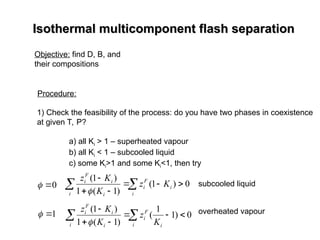
Procedure:
1) Check the feasibility of the process: do you have two phases in coexistence
at given T, P?
a) all Ki > 1 – superheated vapour
b) all Ki < 1 – subcooled liquid
c) some Ki>1 and some Ki<1, then try
0
0
)
1
(
)
1
(
1
)
1
(
i
i
F
i
i i
i
F
i
K
z
K
K
z
subcooled liquid
overheated vapour
1
0
)
1
1
(
)
1
(
1
)
1
(
i i
F
i
i i
i
F
i
K
z
K
K
z
34.
Isothermal multicomponent flashseparation
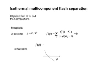
Isothermal multicomponent flash separation
Objective: find D, B, and
their compositions
Procedure:
i i
i
F
i
K
K
z
f 0
)
1
(
1
)
1
(
)
(
2) solve for F
D /
a) Guessing
)
(
f
35.
Isothermal multicomponent flashseparation
Isothermal multicomponent flash separation
Objective: find D, B, and
their compositions
Procedure:
i i
i
F
i
K
K
z
f 0
)
1
(
1
)
1
(
)
(
2) solve for F
D /
b) Newton-Raphson
)
(
'
)
(
)
(
)
(
)
(
)
1
(
k
k
k
k
f
f
i i
i
F
i
K
K
z
f 2
2
)
1
(
1
)
1
(
)
(
'
36.
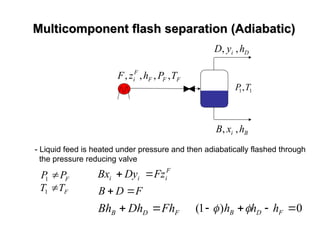
Multicomponent flash separation(Adiabatic)
Multicomponent flash separation (Adiabatic)
B
i h
x
B ,
,
D
i h
y
D ,
,
F
F
F
F
i T
P
h
z
F ,
,
,
,
1
1,T
P
- Liquid feed is heated under pressure and then adiabatically flashed through
the pressure reducing valve
F
F
T
T
P
P
1
1
F
i
i
i Fz
Dy
Bx
F
D
B
F
D
B Fh
Dh
Bh
0
)
1
(
F
D
B h
h
h
37.
Multicomponent flash separation(Adiabatic)
Multicomponent flash separation (Adiabatic)
B
i h
x
B ,
,
D
i h
y
D ,
,
F
F
F
F
i T
P
h
z
F ,
,
,
,
1
1,T
P
- Liquid feed is heated under pressure and then adiabatically flashed through
the pressure reducing valve
F
F
T
T
P
P
1
1
F
i
i
i Fz
Dy
Bx
F
D
B
F
D
B Fh
Dh
Bh
0
)
1
(
F
D
B h
h
h
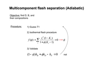
38.
Multicomponent flash separation(Adiabatic)
Multicomponent flash separation (Adiabatic)
Objective: find D, B, and
their compositions
Procedure: 1) Guess T1
2) Isothermal flash procedure
3) Validate
0
)
1
(
F
D
B h
h
h
not
i i
i
F
i
K
K
z
f 0
)
1
(
1
)
1
(
)
(
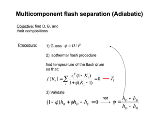
39.
Multicomponent flash separation(Adiabatic)
Multicomponent flash separation (Adiabatic)
Objective: find D, B, and
their compositions
Procedure: 1) Guess
2) Isothermal flash procedure
find temperature of the flash drum
so that:
3) Validate
0
)
1
(
F
D
B h
h
h
not
i i
i
F
i
i
K
K
z
K
f 0
)
1
(
1
)
1
(
)
(
F
D /
B
D
B
F
h
h
h
h
1
T
40.
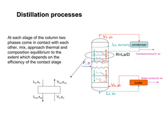
Distillation processes
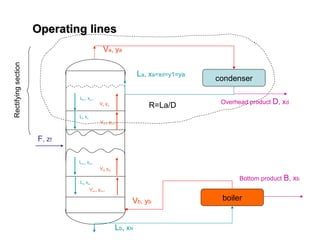
Distillation processes
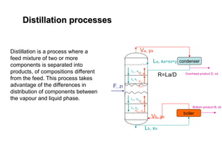
Distillationis a process where a
feed mixture of two or more
components is separated into
products, of compositions different
from the feed. This process takes
advantage of the differences in
distribution of components between
the vapour and liquid phase.
F, zf
Va, ya
La, xa=xd=y1=ya
Lb, xN
Ln-1 xn-1
Vn yn
Ln xn
Vn+1
yn+1
Lm-1 xm-1
Vm ym
Lm xm
Vm+1 ym+1
condenser
Overhead product D, xd
boiler
Vb, yb
Bottom product B, xb
R=La/D
41.
Distillation processes
Distillation processes
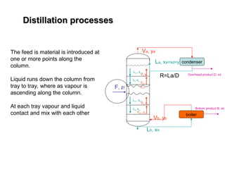
Thefeed is material is introduced at
one or more points along the
column.
Liquid runs down the column from
tray to tray, where as vapour is
ascending along the column.
At each tray vapour and liquid
contact and mix with each other
F, zf
Va, ya
La, xa=xd=y1=ya
Lb, xN
Ln-1 xn-1
Vn yn
Ln xn
Vn+1
yn+1
Lm-1 xm-1
Vm ym
Lm xm
Vm+1 ym+1
condenser
Overhead product D, xd
boiler
Vb, yb
Bottom product B, xb
R=La/D
42.
Distillation processes
Distillation processes
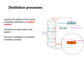
Liquidat the bottom of the column
is partially vaporized in a heated
reboiler.
The boil-up is send back to the
column.
The rest is withdrawn as bottoms,
or bottoms product
F, zf
Va, ya
La, xa=xd=y1=ya
Lb, xN
Ln-1 xn-1
Vn yn
Ln xn
Vn+1
yn+1
Lm-1 xm-1
Vm ym
Lm xm
Vm+1 ym+1
condenser
Overhead product D, xd
boiler
Vb, yb
Bottom product B, xb
R=La/D
43.
Distillation processes
Distillation processes
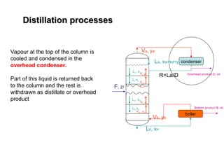
Vapourat the top of the column is
cooled and condensed in the
overhead condenser.
Part of this liquid is returned back
to the column and the rest is
withdrawn as distillate or overhead
product
F, zf
Va, ya
La, xa=xd=y1=ya
Lb, xN
Ln-1 xn-1
Vn yn
Ln xn
Vn+1
yn+1
Lm-1 xm-1
Vm ym
Lm xm
Vm+1 ym+1
condenser
Overhead product D, xd
boiler
Vb, yb
Bottom product B, xb
R=La/D
44.
Distillation processes
Distillation processes
Ateach stage of the column two
phases come in contact with each
other, mix, approach thermal and
composition equilibrium to the
extent which depends on the
efficiency of the contact stage F, zf
Va, ya
La, xa=xd=y1=ya
Lb, xN
Ln-1 xn-1
Vn yn
Ln xn
Vn+1
yn+1
Lm-1 xm-1
Vm ym
Lm xm
Vm+1 ym+1
condenser
Overhead product D, xd
boiler
Vb, yb
Bottom product B, xb
R=La/D
Lin,xin
Lout,xout
Vout,yout
Vin,yin
45.
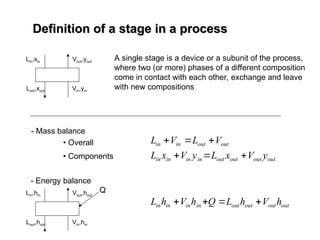
Definition of astage in a process
Definition of a stage in a process
A single stage is a device or a subunit of the process,
where two (or more) phases of a different composition
come in contact with each other, exchange and leave
with new compositions
Lin,xin
Lout,xout
Vout,yout
Vin,yin
- Mass balance
• Overall
• Components
out
out
in
in V
L
V
L
out
out
out
out
in
in
in
in y
V
x
L
y
V
x
L
- Energy balance
Lin,hin
Lout,hout
Vout,hout
Vin,hin
Q
out
out
out
out
in
in
in
in h
V
h
L
Q
h
V
h
L
46.
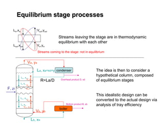
Equilibrium stage processes
Equilibriumstage processes
Streams leaving the stage are in thermodynamic
equilibrium with each other
Lin,xin
Lout,xout
Vout,yout
Vin,yin
Streams coming to the stage: not in equilibrium
F, zf
Va, ya
La, xa=xd=y1=ya
Lb, xN
Ln-1 xn-1
Vn yn
Ln xn
Vn+1
yn+1
Lm-1 xm-1
Vm ym
Lm xm
Vm+1 ym+1
condenser
Overhead product D, xd
boiler
Vb, yb
Bottom product B, xb
R=La/D
The idea is then to consider a
hypothetical column, composed
of equilibrium stages
This idealistic design can be
converted to the actual design via
analysis of tray efficiency
47.
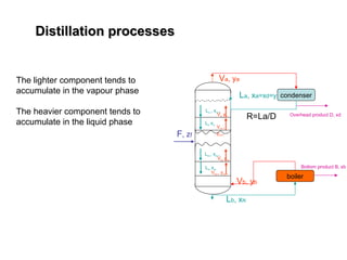
Distillation processes
Distillation processes
Thelighter component tends to
accumulate in the vapour phase
The heavier component tends to
accumulate in the liquid phase
F, zf
Va, ya
La, xa=xd=y1=ya
Lb, xN
Ln-1 xn-1
Vn yn
Ln xn
Vn+1
yn+1
Lm-1 xm-1
Vm ym
Lm xm
Vm+1 ym+1
condenser
Overhead product D, xd
boiler
Vb, yb
Bottom product B, xb
R=La/D
48.
Distillation processes
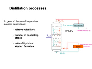
Distillation processes
Ingeneral, the overall separation
process depends on:
- relative volatilities
relative volatilities
- number of contacting
number of contacting
stages
stages
- ratio of liquid and
ratio of liquid and
vapour flowrates
vapour flowrates
F, zf
Va, ya
La, xa=xd=y1=ya
Lb, xN
Ln-1 xn-1
Vn yn
Ln xn
Vn+1
yn+1
Lm-1 xm-1
Vm ym
Lm xm
Vm+1 ym+1
condenser
Overhead product D, xd
boiler
Vb, yb
Bottom product B, xb
R=La/D
49.
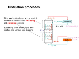
Distillation processes
Distillation processes
Ifthe feed is introduced at one point, it
divides the column into a rectifying
and stripping sections
But usually there are multiple feed
location and various side streams F, zf
Va, ya
La, xa=xd=y1=ya
Lb, xN
Ln-1 xn-1
Vn yn
Ln xn
Vn+1
yn+1
Lm-1 xm-1
Vm ym
Lm xm
Vm+1 ym+1
condenser
Overhead product D, xd
boiler
Vb, yb
Bottom product B, xb
R=La/D
50.
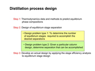
Distillation process design
Distillationprocess design
Step 1: Thermodynamics data and methods to predict equilibrium
phase compositions
Step 2: Design of equilibrium stage separation
• Design problem type 1: To determine the number
of equilibrium stages required to accomplish the
desired separations
• Design problem type 2: Given a particular column
design, determine separation that can be accomplished
Step 3: Develop an actual design by applying the stage efficiency analysis
to equilibrium stage design
51.
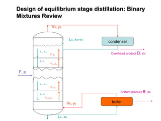
Design of equilibriumstage distillation: Binary
Design of equilibrium stage distillation: Binary
Mixtures Review
Mixtures Review
Va, ya
La, xa=xd
F, zf
Lb, xN
Ln-1 xn-1
Vn yn
Ln xn
Vn+1 yn+1
Lm-1 xm-1
Vm ym
Lm xm
Vm+1 ym+1
condenser
Overhead product D, xd
boiler
Vb, yb
Bottom product B, xb
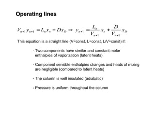
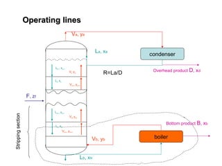
Operating lines
Operating lines
D
n
n
n
n
n
D
n
n
n
nx
V
D
x
V
L
y
Dx
x
L
y
V
1
1
1
1
1
This equation is a straight line (V=const, L=const, L/V=const) if:
- Two components have similar and constant molar
enthalpies of vaporization (latent heats)
- Component sensible enthalpies changes and heats of mixing
are negligible (compared to latent heats)
- The column is well insulated (adiabatic)
- Pressure is uniform throughout the column
54.
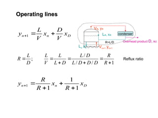
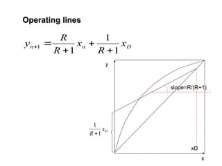
Operating lines
Operating lines
D
n
nx
V
D
x
V
L
y
1
1
/
/
/
;
R
R
D
D
D
L
D
L
D
L
L
V
L
D
L
R Reflux ratio
Va, ya
La, xa
Ln xn Vn+1 yn+1
condenser
Overhead product D, xd
R=L/D
D
n
n x
R
x
R
R
y
1
1
1
1
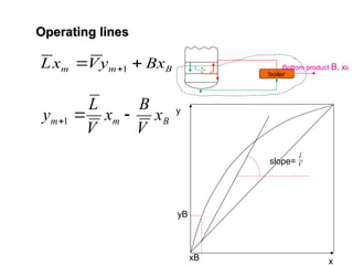
B
m
m Bx
y
V
x
L
1
Operating lines
Operating lines
Lm xm
Vm+1 ym+1
boiler
Bottom product B, xb
B
m
m x
V
B
x
V
L
y
1
y
x
xB
yB
slope= V
L
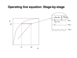
58.
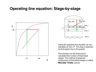
Operating line equation:Stage-by-stage
Operating line equation: Stage-by-stage
y
x
xa
ya
Va, ya
La, xa
Plate 1
Plate 2
Plate 3
L1, x1
x1
59.
Operating line equation:Stage-by-stage
Operating line equation: Stage-by-stage
y
x
xa
ya
Va, ya
La, xa
Plate 1
Plate 2
Plate 3
L1, x1
x1
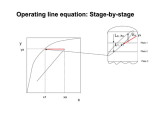
60.
Operating line equation:Stage-by-stage
Operating line equation: Stage-by-stage
y
x
xa
ya
Va, ya
La, xa
Plate 1
Plate 2
Plate 3
Using the operating line equation we can
calculate y2 from x1. This step is depicted
by think green line in the graphs.
This process can be continued to
calculated the number of theoretical
stages. This method of graphical
construction of theoretical stages is called
McCabe Thiele method
L1, x1
x1
V2, y2
61.
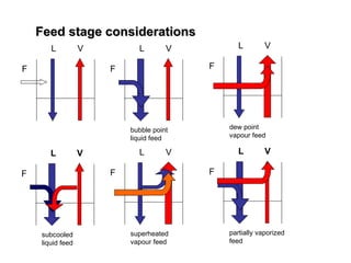
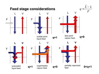
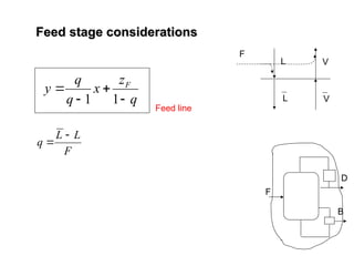
Feed stage considerations
Feedstage considerations
L V
F
L V
F
bubble point
liquid feed
L V
F
dew point
vapour feed
L V
F
subcooled
liquid feed
F
L V
superheated
vapour feed
L V
F
partially vaporized
feed
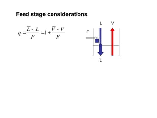
Feed stage considerations
Feedstage considerations
L V
F
L V
F
bubble point
liquid feed
L V
F
dew point
vapour feed
L V
F
subcooled
liquid feed
F
L V
superheated
vapour feed
L V
F
partially vaporized
feed
q=1 q=0
q>1 q<0 0<q<1
F
L
L
q
q
z
x
q
q
y F
1
1
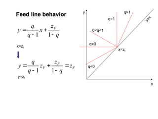
Feed linebehavior
Feed line behavior
x=zf
F
F
F z
q
z
z
q
q
y
1
1
y=zf
y
=
x
x=zf
q<0
q=0
0<q<1
q=1
q>1
y
x
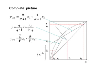
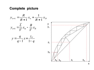
66.
Complete picture
Complete picture
D
n
nx
R
x
R
R
y
1
1
1
1
B
m
n x
V
B
x
V
L
y
1
q
z
x
q
q
y F
1
1
y
x
zf
zf
xB xD
y1
yB
xN
D
x
R 1
1
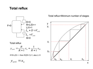
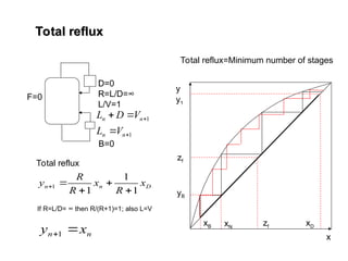
Total reflux
Total reflux
F=0
D=0
R=L/D=∞
L/V=1
B=0
Totalreflux
D
n
n x
R
x
R
R
y
1
1
1
1
If R=L/D= ∞ then R/(R+1)=1; also L=V
n
n x
y
1
y
x
zf
zf
xB xD
y1
yB
xN
Total reflux=Minimum number of stages
1
1
n
n
n
n
V
L
V
D
L
71.
Total reflux
Total reflux
F=0
D=0
R=L/D=∞
L/V=1
B=0
Totalreflux
D
n
n x
R
x
R
R
y
1
1
1
1
If R=L/D= ∞ then R/(R+1)=1; also L=V
n
n x
y
1
y
x
zf
zf
xB xD
y1
yB
xN
Total reflux=Minimum number of stages
1
1
n
n
n
n
V
L
V
D
L
72.
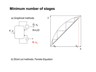
Minimum number ofstages
Minimum number of stages
a) Graphical methods
R=L/D
F, z
D, xD
B, xB
y
x
xB xD
b) Short cut methods: Fenske Equation
y
x
zf
zf
xB xD
y1
yB
xN
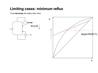
If wedecrease the reflux ratio, then
D
n
n x
R
x
R
R
y
1
1
1
1
B
m
n x
V
B
x
V
L
y
1
q
z
x
q
q
y F
1
1
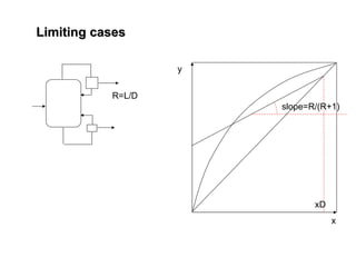
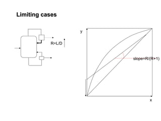
Limiting cases: minimum reflux
Limiting cases: minimum reflux
77.
Limiting cases: minimumreflux
Limiting cases: minimum reflux
y
x
zf
zf
xB xD
y1
yB
xN
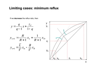
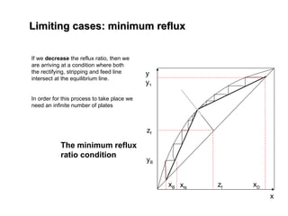
If we decrease the reflux ratio, then we
are arriving at a condition where both
the rectifying, stripping and feed line
intersect at the equilibrium line.
In order for this process to take place we
need an infinite number of plates
The minimum reflux
ratio condition
78.
Limiting cases: minimumreflux
Limiting cases: minimum reflux
D
n
n x
R
x
R
R
y
1
1
1
1
y
x
zf
zf
xB xD
y1
yB
xN
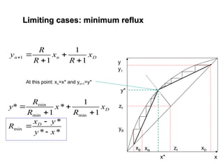
At this point: xn=x* and yn+1=y*
x*
y*
*
*
*
1
1
*
1
*
min
min
min
min
x
y
y
x
R
x
R
x
R
R
y
D
D


![Fenske Equation
Fenske Equation
B
B
AB
N
AB
AB
D
D
x
x
x
x
1
1
,
1
,
2
,
1
B
B
N
D
D
x
x
x
x
1
)
(
1
1
min
1
ln
)]
1
(
/
)
1
(
ln[
min
AB
D
B
B
D x
x
x
x
N
Fenske equation](https://image.slidesharecdn.com/l1-2-3-4-250901200512-b80cf1ad/85/Unit-Operation-and-Separation-Process-Basic-73-320.jpg)