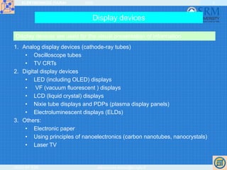
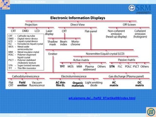
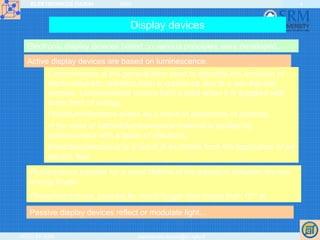
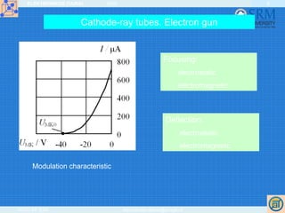
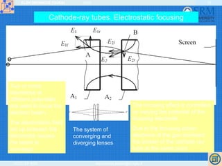
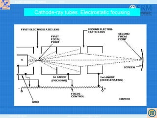
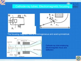
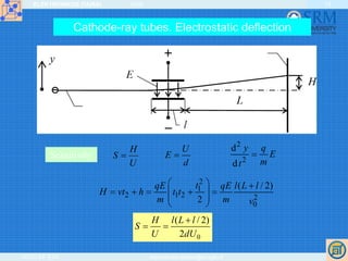
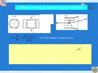
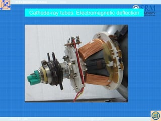
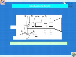
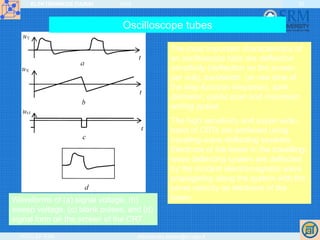
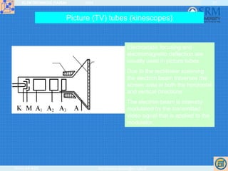
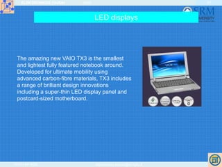
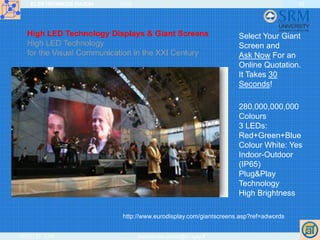
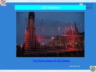
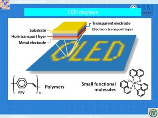
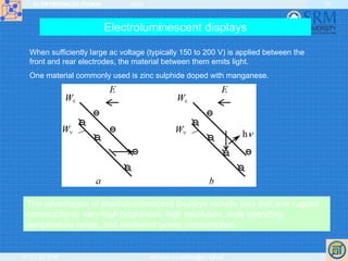
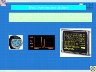
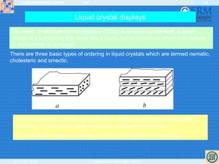
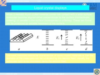
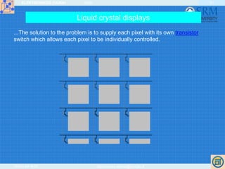
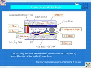
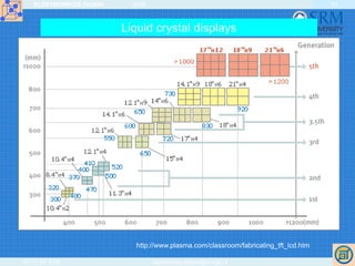
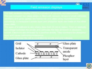
SlideShare a Scribd company logo
ELEKTRONIKOS ĮTAISAI 2009
VGTU EF ESK stanislovas.staras@el.vgtu.lt
1
DISPLAY DEVICES
ELEKTRONIKOS ĮTAISAI 2009
VGTU EF ESK stanislovas.staras@el.vgtu.lt
2
Display devices
Display devices are used for the visual presentation of information.
1. Analog display devices (cathode-ray tubes)
• Oscilloscope tubes
• TV CRTs
2. Digital display devices
• LED (including OLED) displays
• VF (vacuum fluorescent ) displays
• LCD (liquid crystal) displays
• Nixie tube displays and PDPs (plasma display panels)
• Electroluminescent displays (ELDs)
3. Others:
• Electronic paper
• Using principles of nanoelectronics (carbon nanotubes, nanocrystals)
• Laser TV
ELEKTRONIKOS ĮTAISAI 2009
VGTU EF ESK stanislovas.staras@el.vgtu.lt
3
Classification of electronic information technologies with high information content; highlighted technologies are treated in this article
w4.siemens.de/.../heft2_97/artikel08/index.html
ELEKTRONIKOS ĮTAISAI 2009
VGTU EF ESK stanislovas.staras@el.vgtu.lt
4
Display devices
Electronic display devices based on various principles were developed.
Active display devices are based on luminescence.
Luminescence is the general term used to describe the emission of
electromagnetic radiation from a substance due to a non-thermal
process. Luminescence occurs from a solid when it is supplied with
some form of energy.
Photoluminescence arises as a result of absorption of photons.
In the case of cathodoluminescence material is excited by
bombardment with a beam of electrons.
Electroluminescence is a result of excitation from the application of an
electric field.
Fluorescence persists for a short lifetime of the transition between the two
energy levels.
Phosphorescence persists for much longer time (more than 10-8 s).
Passive display devices reflect or modulate light…
ELEKTRONIKOS ĮTAISAI 2009
VGTU EF ESK stanislovas.staras@el.vgtu.lt
5
Display devices. Content and objectives
Cathode ray tubes
Electron gun
Principles of focusing
Deflection of the beam
Cathodoluminescence
Oscilloscope tubes
Picture tubes
Flat panel displays
LED displays
Vacuum fluorescent displays
Gas discharge displays and plasma display panels
Electroluminescent displays
Liquid crystal displays
Field emission displays
Other displays
Objectives: overview structures, principles of operation and
general properties of display devices.
ELEKTRONIKOS ĮTAISAI 2009
VGTU EF ESK stanislovas.staras@el.vgtu.lt
6
Karl Ferdinand Braun a German physicist, interested in the just discovered
Cathode rays, … developed the first cold Cathode Ray tube with magnetically
beam deflection … and a mica screen covered with phosphor to produce a
visible spot. This tube, build for him by Franz Müller … was called after its
inventor, the Braun tube. JJ.Thomson used a similar tube design in his
experiments to show the existence of the electron almost at the same time.
Braun used this tube as an indicator tube for studying the effects of Cathode rays
and described this 1897, this was in fact the first oscilloscope. Harris J Ryan
introduced this tube in 1903 in the USA as an alternating current wave indicator,
known as the Braun-Ryan tube.
Cathode-ray tubes
The Braun tube, this early 1900
tube is in fact a cold Cathode
Crookes tube with an internal
mica screen covered with
phosphorescent paint. The neck
contains glass diaphragm with a
small 2mm hole to let only a tiny
electron beam go through
(focus) which can be deflected by
an (electro) magnet to produce a
spot on the screen.
ELEKTRONIKOS ĮTAISAI 2009
VGTU EF ESK stanislovas.staras@el.vgtu.lt
7
Cathode-ray tubes
The cathode ray tube (CRT), invented by German physicist Karl Ferdinand
Braun in 1897, is an evacuated glass envelope containing an electron gun (a
source of electrons) and a fluorescent screen, usually with internal or external
means to accelerate and deflect the electrons. When electrons strike the
fluorescent screen, light is emitted.
The electron beam is deflected and modulated in a way which causes it to
display an image on the screen. The image may represent electrical
waveforms (oscilloscope), pictures (television, computer monitor), echoes of
aircraft detected by radar, etc.
A cathode ray tube (CRT) contains four basic parts:
• electron gun,
• focusing and accelerating systems,
• deflecting systems, and
• evacuated glass envelope with a phosphorescent screen that glows
visibly when struck by the electron beam.
ELEKTRONIKOS ĮTAISAI 2009
VGTU EF ESK stanislovas.staras@el.vgtu.lt
8
Cathode-ray tubes. Electron gun
An electron gun consists of a series of electrodes
producing a narrow beam of high-velocity electrons.
Electrons are released from the indirectly heated
cathode.
The intensity of the beam is controlled by variation of
the negative potential of the cylindrical control grid
surrounding the cathode. This electrode is called the
modulator.
The control grid has a hole in the front to allow passage
of the electron beam.
The electrons are accelerated and focused.
ELEKTRONIKOS ĮTAISAI 2009
VGTU EF ESK stanislovas.staras@el.vgtu.lt
9
Cathode-ray tubes. Electron gun
Modulation characteristic
Focusing:
electrostatic
electromagnetic
Deflection:
electrostatic
electromagnetic
ELEKTRONIKOS ĮTAISAI 2009
VGTU EF ESK stanislovas.staras@el.vgtu.lt
10
Cathode-ray tubes. Electrostatic focusing
The focusing effect is controlled
by varying the potential of the
focusing electrode.
Due to the focusing action
electrons of the gun bombard
the screen of the cathode ray
tube at the same point.
Two or more
electrodes at
different potentials
are used to focus the
electron beam.
The electrostatic field
set up between the
electrodes causes
the beam to
converge.
The system of
converging and
diverging lenses
ELEKTRONIKOS ĮTAISAI 2009
VGTU EF ESK stanislovas.staras@el.vgtu.lt
11
Cathode-ray tubes. Electrostatic focusing
ELEKTRONIKOS ĮTAISAI 2009
VGTU EF ESK stanislovas.staras@el.vgtu.lt
12
Cathode-ray tubes. Electromagnetic focusing
Focus coil
The focusing magnetic field is inhomogeneous and axial symmetrical.
Cathode ray tube employing
electromagnetic focus and
deflection
ELEKTRONIKOS ĮTAISAI 2009
VGTU EF ESK stanislovas.staras@el.vgtu.lt
13
Cathode-ray tubes. Electrostatic deflection
Electron
beam
Screen
H
S
U
=
U
E
d
=
2
2
d
d
y q
E
mt
=
2
1
2 1 2 2
0
( / 2)
2
tqE qE l L l
H vt h t t
m m v
⎛ ⎞ +
= + = + =⎜ ⎟
⎜ ⎟
⎝ ⎠
02
)2/(
dU
lLl
U
H
S
+
==
Sensitivity
ELEKTRONIKOS ĮTAISAI 2009
VGTU EF ESK stanislovas.staras@el.vgtu.lt
14
Cathode-ray tubes. Electromagnetic deflection
Vertical
deflection
coil
Glass
balloon
0
)2/(
U
lLl
k
NI
H
S
+
== NI is the number of ampere-turns
The sensitivity of a CRT with electrostatic deflecting system is in inverse ratio to
U0. In the case of electromagnetic deflection it is in inverse ratio to .
Using electromagnetic deflection we can obtain relatively great sensitivity and
great deflection angle at high accelerating voltage . For this reason
electromagnetic deflection is used in television picture tubes, requiring high-
velocity electron beams necessary for bright display.
0U
ELEKTRONIKOS ĮTAISAI 2009
VGTU EF ESK stanislovas.staras@el.vgtu.lt
15
Cathode-ray tubes. Electromagnetic deflection
ELEKTRONIKOS ĮTAISAI 2009
VGTU EF ESK stanislovas.staras@el.vgtu.lt
16
Cathode-ray tubes. Electromagnetic deflection
ELEKTRONIKOS ĮTAISAI 2009
VGTU EF ESK stanislovas.staras@el.vgtu.lt
17
Cathode-ray tubes. Electromagnetic deflection
ELEKTRONIKOS ĮTAISAI 2009
VGTU EF ESK stanislovas.staras@el.vgtu.lt
18
Cathode-ray tubes. Cathodoluminescence
The deflected and accelerated electron beam strikes a phosphorescent
material on the inside face of the tube. The phosphor glows and the visible
glow can be seen at the front of the tube. So cathodoluminescence is used in
cathode ray tubes.
Cathodoluminescent efficiency increases with increasing beam voltage.
As a result of the screen bombardment free electrons are knocked out. To
collect these electrons the inside surface of the glass balloon is coated by
conducting aquadag layer. Usually this layer is connected to the accelerating
anode.
The screen of the CRT may be coated with aluminium on the inside and this
coating is held at anode potential. Such an aluminized screen prevents the
accumulation of charge on the phosphor and improves its performance
increasing the visible output and reducing the effects of ion bombardment.
ELEKTRONIKOS ĮTAISAI 2009
VGTU EF ESK stanislovas.staras@el.vgtu.lt
19
Oscilloscope tubes
Brightness
Focus
Electrostatic focusing and electrostatic deflection
ELEKTRONIKOS ĮTAISAI 2009
VGTU EF ESK stanislovas.staras@el.vgtu.lt
20
Waveforms of (a) signal voltage, (b)
sweep voltage, (c) blank pulses, and (d)
signal form on the screen of the CRT
The most important characteristics of
an oscilloscope tube are deflection
sensitivity (deflection on the screen
per volt), bandwidth (or rise time of
the step-function response), spot
diameter, useful scan and maximum
writing speed.
The high sensitivity and super-wide-
band of CRTs are achieved using
traveling-wave deflecting systems.
Electrons of the beam in the travelling-
wave deflecting system are deflected
by the incident electromagnetic wave
propagating along the system with the
same velocity as electrons of the
beam.
Oscilloscope tubes
ELEKTRONIKOS ĮTAISAI 2009
VGTU EF ESK stanislovas.staras@el.vgtu.lt
21
Picture (TV) tubes (kinescopes)
Deflecting
system
Deflecting system
Phosphor
Electrostatic focusing and
electromagnetic deflection are
usually used in picture tubes.
Due to the rectilinear scanning
the electron beam traverses the
screen area in both the horizontal
and vertical directions.
The electron beam is intensity
modulated by the transmitted
video signal that is applied to the
modulator.
ELEKTRONIKOS ĮTAISAI 2009
VGTU EF ESK stanislovas.staras@el.vgtu.lt
22
Picture (TV) tubes (kinescopes)
The horizontal direction is termed the line and the vertical direction the field.
Saw-tooth current waveforms are used to produce the deflection of the beam.
The fly-back period is blanked out.
The number of lines traversed per second is the line frequency.
The number of vertical scans per second is the field frequency.
A method of scanning that produces the entire picture in a single field (or raster)
is termed sequential scanning.
Most broadcast television systems use a system of interlaced scanning. In this
system the lines of successive rasters are not superimposed on each other but
are interlaced.
Two rasters constitute a complete picture or frame. The number of complete
pictures per second is the frame frequency which is half the number of rasters
per second, i. e. half the field frequency.
The field frequency needs to be relatively slow to allow as many horizontal lines
as possible but sufficiently fast to eliminate flicker.
ELEKTRONIKOS ĮTAISAI 2009
VGTU EF ESK stanislovas.staras@el.vgtu.lt
23
The sequential (progressive) and interlaced scanning
Picture (TV) tubes (kinescopes)
ELEKTRONIKOS ĮTAISAI 2009
VGTU EF ESK stanislovas.staras@el.vgtu.lt
24
Color picture tubes
The colored image is produced varying the intensity of excitation of the three
different phosphors that produce the three primary colors (red, green and blue)
and reproduce the original colors of the image by an additive color process.
Electron
beam
Mask
Screen
The triangular arrangement of electron guns are used. The phosphors are
arranged as triangular sets of coloured dots.
A metal shadow mask is placed directly behind the screen in the plane of
intersection of the electron beams to ensure that each beam hits the correct
phosphor. The mask acts as a physical barrier to the beams as they progress
from one location to the next and minimizes the generation of spurious colours
by excitation of the wrong phosphor.
ELEKTRONIKOS ĮTAISAI 2009
VGTU EF ESK stanislovas.staras@el.vgtu.lt
25
Color picture tubes
Screen
Mask
Electron
gun
Slot matrix tube
ELEKTRONIKOS ĮTAISAI 2009
VGTU EF ESK stanislovas.staras@el.vgtu.lt
26
ELEKTRONIKOS ĮTAISAI 2009
VGTU EF ESK stanislovas.staras@el.vgtu.lt
27
ELEKTRONIKOS ĮTAISAI 2009
VGTU EF ESK stanislovas.staras@el.vgtu.lt
28
FLAT PANEL DISPLAYS
CRTs are relatively fragile and bulky.
Other types of thinner displays were developed. They are often called flat
panel displays.
Most flat-panel displays form digits or characters with combination of
segments or dots. The arrangement of these elements is called the display
font.
The most common format for numeric display is the seven-segment font.
Graphic displays are like very large dot matrices. Each dot in a graphic
display is called picture element, pixel or pel. The capabilities of a graphic
display depend on number of pixels horizontally and vertically.
ELEKTRONIKOS ĮTAISAI 2009
VGTU EF ESK stanislovas.staras@el.vgtu.lt
29
Flat panel displays requiring continuous refresh:
DLP (Digital Light Processing)
Plasma displays
Liquid crystal displays (LCDs)
Organic light-emitting diode displays (OLEDs)
Light-emitting diode display (LED)
Electroluminescent displays (ELDs)
Surface-conduction electron-emitter displays (SEDs)
Field emission displays (FEDs)
Nano-emissive display (NEDs)
Only the first five of these displays are
commercially available today, though OLED
displays are beginning deployment only in small
sizes (mainly in cellular telephones).
http://en.wikipedia.org/wiki/Flat_panel_display
Flat panel displays
ELEKTRONIKOS ĮTAISAI 2009
VGTU EF ESK stanislovas.staras@el.vgtu.lt
30
LED displays
Light emitting diodes are used in LED displays.
Operation of the LED displays is based on the injection luminescence.
LED displays are available in many different sizes and shapes.
Usually LED displays radiate red, orange, yellow or green light.
They have a wide operating temperature range, are inexpensive, easily
interfaced to digital logic, easily multiplexed, do not require high voltages
and have fast response time.
The viewing angle is good and display of arbitrary numbers of digits is
easily assembled.
ELEKTRONIKOS ĮTAISAI 2009
VGTU EF ESK stanislovas.staras@el.vgtu.lt
31
The amazing new VAIO TX3 is the smallest
and lightest fully featured notebook around.
Developed for ultimate mobility using
advanced carbon-fibre materials, TX3 includes
a range of brilliant design innovations
including a super-thin LED display panel and
postcard-sized motherboard.
LED displays
ELEKTRONIKOS ĮTAISAI 2009
VGTU EF ESK stanislovas.staras@el.vgtu.lt
32
High LED Technology Displays & Giant Screens
High LED Technology
for the Visual Communication in the XXI Century
http://www.eurodisplay.com/giantscreens.asp?ref=adwords
Select Your Giant
Screen and
Ask Now For an
Online Quotation.
It Takes 30
Seconds!
280,000,000,000
Colours
3 LEDs:
Red+Green+Blue
Colour White: Yes
Indoor-Outdoor
(IP65)
Plug&Play
Technology
High Brightness
ELEKTRONIKOS ĮTAISAI 2009
VGTU EF ESK stanislovas.staras@el.vgtu.lt
33
LED displays
The World Largest 3D LED Display
static.flickr.com
ELEKTRONIKOS ĮTAISAI 2009
VGTU EF ESK stanislovas.staras@el.vgtu.lt
34
LED displays
ELEKTRONIKOS ĮTAISAI 2009
VGTU EF ESK stanislovas.staras@el.vgtu.lt
35
Some displays can show only digits or alphanumeric characters. They are
called segment displays, because they are composed of several segments
that switch on and off. There are several types:
Seven segment display (most common, digits only)
Fourteen segment display
Sixteen segment display
Vacuum fluorescent displays
ELEKTRONIKOS ĮTAISAI 2009
VGTU EF ESK stanislovas.staras@el.vgtu.lt
36
A grid of tiny electrodes applies an electric current to the individual
cells, causing the gas (a mix of neon and xenon) in the cells to ionize.
This ionized gas (plasma) emits high-frequency UV rays, which
stimulate the cells' phosphors, causing them to glow the desired color.
Gas discharge displays and plasma display panels
ELEKTRONIKOS ĮTAISAI 2009
VGTU EF ESK stanislovas.staras@el.vgtu.lt
37
Gas discharge displays and plasma display panels
ELEKTRONIKOS ĮTAISAI 2009
VGTU EF ESK stanislovas.staras@el.vgtu.lt
38
Electroluminescent displays
EL was first observed in 1907 by Captain Henry Joseph Round in silicon carbide (SiC),
although ELD technology was not made commercially available until the 1980s.
http://www.indiana.edu/~hightech/fpd/papers/ELDs.html
The electroluminescent display is similar in idea to an ac plasma display, except
that the gas-filled area is replaced by a thin film of electroluminescent material.
ELEKTRONIKOS ĮTAISAI 2009
VGTU EF ESK stanislovas.staras@el.vgtu.lt
39
The advantages of electroluminescent displays include very thin and rugged
constructions, very high brightness, high resolution, wide operating
temperature range, and moderate power consumption.
When sufficiently large ac voltage (typically 150 to 200 V) is applied between the
front and rear electrodes, the material between them emits light.
One material commonly used is zinc sulphide doped with manganese.
Electroluminescent displays
ELEKTRONIKOS ĮTAISAI 2009
VGTU EF ESK stanislovas.staras@el.vgtu.lt
40
ELDs are particularly useful in applications where full color is not required
but where ruggedness, speed, brightness, high contrast, and a wide angle of
vision is needed.
Electroluminescent displays
ELEKTRONIKOS ĮTAISAI 2009
VGTU EF ESK stanislovas.staras@el.vgtu.lt
41
Liquid crystal displays
The heart of all liquid crystal displays (LCDs) is a liquid crystal itself. A liquid
crystal is a substance that flows like a liquid, but its molecules orient themselves
in the manner of a crystal.
In the cholesteric crystals molecules form planes. A plane has nematic-like
structure, but with each plane molecules change their direction.
As a result the molecules display a helical twist through the material.
There are three basic types of ordering in liquid crystals which are termed nematic,
cholesteric and smectic.
ELEKTRONIKOS ĮTAISAI 2009
VGTU EF ESK stanislovas.staras@el.vgtu.lt
42
Liquid crystal displays
When a nematic liquid crystal material comes into contact with a solid surface
molecules become aligned either perpendicular to the surface (homeotropic
ordering) or parallel to the surface (homogeneous ordering). These two forms
can be produced by suitable treatment of the surface.
The most important electrical characteristic of liquid crystal materials is that the
direction of the molecules can be controlled by the electric field. Usually the
molecules tend to be orientated along the electric field.
ELEKTRONIKOS ĮTAISAI 2009
VGTU EF ESK stanislovas.staras@el.vgtu.lt
43
Liquid crystal displays
Most of the LCDs use twisted nematic cells.
When a beam of polarised light is incident on the cell the liquid causes
rotation of polarisation plane.
A strong enough electric field changes orientation of molecules and in this
state the molecules have no effect on an incident light beam.
ELEKTRONIKOS ĮTAISAI 2009
VGTU EF ESK stanislovas.staras@el.vgtu.lt
44
Liquid crystal displays
In the most common type of LCD cell based on twisted nematic field effect, two
sheets of glass form the main structure. Between the sheets of glass there is a
very thin layer of liquid crystal material. The inner surface of each piece of glass
is coated with a transparent, conductive layer of metal oxide. The sandwich is
completed with a polarizer on the outside of each piece of glass and a reflector
on the back of the display.
ELEKTRONIKOS ĮTAISAI 2009
VGTU EF ESK stanislovas.staras@el.vgtu.lt
45
Liquid crystal displays
Transmission LCD displays do not have the reflector and
must be provided with rear illumination. They operate in a
very similar fashion to the reflective displays.
Colour displays are possible by incorporating colour filters.
An LCD cell consumes only microwatts of power over a
thousand times less than LED displays.
LCDs can operate on voltages as low as 2 to 3 V and are
easily driven by MOS IC drivers.
LCDs also have their disadvantages. They cannot be seen
in the dark, have a limited viewing angle and a limited
temperature range.
ELEKTRONIKOS ĮTAISAI 2009
VGTU EF ESK stanislovas.staras@el.vgtu.lt
46
Liquid crystal displays
ELEKTRONIKOS ĮTAISAI 2009
VGTU EF ESK stanislovas.staras@el.vgtu.lt
47
The left column electrode is at the same
potential level as the row electrode. To the
right column electrode (red), a different
voltage is applied. In this way, an electric field
is generated in the right pixel oriented
perpendicular to the glass surfaces.
On the picture one can see that the rubbing
direction of the alignment layers (green) on
top and bottom substrate are chosen
perpendicular to each other. Due to this
choice, the director in the left pixel makes a
homogeneous turn of 90° from bottom to top.
Therefore, this type of LCD is called a
'Twisted Nematic LCD' (TN-LCD). If a voltage
is applied to the electrode, the director
reorients to become perpendicular to the
surfaces (right pixel).
http://www.elis.ugent.be/ELISgroups/lcd/lc/lc3.php
Liquid crystal displays
ELEKTRONIKOS ĮTAISAI 2009
VGTU EF ESK stanislovas.staras@el.vgtu.lt
48
Liquid crystal displays
ELEKTRONIKOS ĮTAISAI 2009
VGTU EF ESK stanislovas.staras@el.vgtu.lt
49
The very first types of LCDs were called DSM (dynamic scattering mode), but
TN (twisted nematic) has become the standard today. Almost all active matrix
drive displays use TN type LCDs, and numerous types of active elements are
being developed. The use of TN type LCDs in simple matrix drive displays
causes the contrast to drop as the number of scan lines of the image
displayed is increased.
To compensate for this, new types of LCDs are being researched and
developed. Advances in LCD R&D have already led to the development of
STN (super twisted nematic) type LCDs, which offer high contrast, even on
large screens; and TSTN (triple STN) and FSTN (film STN) LCDs, which
feature a lightweight and thin body design that are optimal for large black-and-
white LCDs and precise color imaging when equipped with a color filter.
http://sharp-world.com/sc/library/lcd_e/s2_4_4e.htm
Liquid crystal displays
From TN to STN, TSTN, and FSTN
ELEKTRONIKOS ĮTAISAI 2009
VGTU EF ESK stanislovas.staras@el.vgtu.lt
50
Normal Liquid Crystal Displays like those found in calculators have
direct driven image elements – a voltage can be applied across one
segment without interfering with other segments of the display. This is
impractical for a large display with a large number of picture elements
(pixels), since it would require millions of connections - top and bottom
connections for each one of the three colors (red, green and blue) of
every pixel.
To avoid this issue, the pixels are addressed in rows and columns
which reduce the connection count from millions to thousands.
Liquid crystal displays
TFT-LCD (Thin Film Transistor-Liquid Crystal Display) is a variant of
Liquid Crystal Display (LCD) which uses Thin-Film Transistor (TFT)
technology to improve image quality. TFT LCD is one type of active
matrix LCD, though it is usually synonymous with LCD. It is used in
both flat panel displays and projectors.
ELEKTRONIKOS ĮTAISAI 2009
VGTU EF ESK stanislovas.staras@el.vgtu.lt
51
...The solution to the problem is to supply each pixel with its own transistor
switch which allows each pixel to be individually controlled.
Liquid crystal displays
ELEKTRONIKOS ĮTAISAI 2009
VGTU EF ESK stanislovas.staras@el.vgtu.lt
52
The TFT-array and color-filter substrates are made into an LCD panel by
assembling them with a sealant (hermetikas).
http://www.plasma.com/classroom/fabricating_tft_lcd.htm
Liquid crystal displays
ELEKTRONIKOS ĮTAISAI 2009
VGTU EF ESK stanislovas.staras@el.vgtu.lt
53
http://www.plasma.com/classroom/fabricating_tft_lcd.htm
Liquid crystal displays
ELEKTRONIKOS ĮTAISAI 2009
VGTU EF ESK stanislovas.staras@el.vgtu.lt
54
Field emission displays
The field emission display (FED) is a product of vacuum microelectronics.
The gap between two glass plates is filled with vacuum. Arrays of small cathodes
(emitters) and grids (gates) are formed on one plate using microelectronics
technology. A transparent anode layer and phosphor layer are made on the other
glass plate.
The apex of a cathode is very sharp, less than 20 nm in radius. Then at relatively
low voltage between the anode and cathodes the field emission of electrons
occurs. Electrons are attracted by a positive anode. They bombard the phosphor
layer and cause cathodoluminescence.
The current across the cell is controlled by anode and grid voltages.
ELEKTRONIKOS ĮTAISAI 2009
VGTU EF ESK stanislovas.staras@el.vgtu.lt
55
The application of a small voltage to a metal or
semiconductor surface containing nanometer
scale protrusions produces a large electric field
which causes electrons to be emitted. Using an
extractor grid, less than 80 volts is sufficient to
produce up to 5m A of emission current from a
single tip.
A single tip in
girded
configuration. An
array of such a
unit cell forms a
pixel in a display
application
Field emission displays
ELEKTRONIKOS ĮTAISAI 2009
VGTU EF ESK stanislovas.staras@el.vgtu.lt
56
Works like a CRT with multiple electron guns at each
pixel.
Field emission displays
ELEKTRONIKOS ĮTAISAI 2009
VGTU EF ESK stanislovas.staras@el.vgtu.lt
57
CNT can be metallic or
semiconducting and offers
amazing possibilities to create
future nanoelectronics devices,
circuits, and computers.
Carbon nanotube displays
ELEKTRONIKOS ĮTAISAI 2009
VGTU EF ESK stanislovas.staras@el.vgtu.lt
58
November 28, 2003
Carbon Nanotube Display
Source: Samsung Display Technology, courtesy of Choi et. al.
www.nanopicoft
heday.org
ELEKTRONIKOS ĮTAISAI 2009
VGTU EF ESK stanislovas.staras@el.vgtu.lt
59
The promise of Motorola's new Nano Emissive Display (NED)
technology is sweet for anyone that covets a flat screen HDTV, but
doesn't want to pony up big bucks.
Imagine a 40 inch HDTV panel less than an inch thick.
Now imagine it costing less than $400.
Motorola Labs unveiled a prototype of NED technology in the form of a
functioning 5-inch color segment of a 1280 x 720, 16:9, 42-inch HDTV.
A prototype model was demonstrated by Motorola in May
2005. Nano-emissive display (NED) is Motorola's term for
their Carbon Nanotubes (CNTs)-based display technology.
Carbon nanotube displays
ELEKTRONIKOS ĮTAISAI 2009
VGTU EF ESK stanislovas.staras@el.vgtu.lt
60
Laser TV
ELEKTRONIKOS ĮTAISAI 2009
VGTU EF ESK stanislovas.staras@el.vgtu.lt
61
E-paper
Electronic paper, also sometimes called e-paper or electronic ink, is a
display technology designed to mimic the appearance of regular ink on
paper. Unlike a conventional flat panel display, which uses a backlight to
illuminate its pixels, electronic paper reflects light like ordinary paper and is
capable of holding text and images indefinitely without drawing electricity,
while allowing the image to be changed later.
ELEKTRONIKOS ĮTAISAI 2009
VGTU EF ESK stanislovas.staras@el.vgtu.lt
62
E-paper
ELEKTRONIKOS ĮTAISAI 2009
VGTU EF ESK stanislovas.staras@el.vgtu.lt
63
THE END

More Related Content

Similar to Unit iv DISPLAY DEVICE

cathode ray oscilloscope
cathode ray oscilloscopecathode ray oscilloscope
cathode ray oscilloscope
hajahrokiah
 
Understanding Lab Instruments
Understanding Lab InstrumentsUnderstanding Lab Instruments
Understanding Lab Instruments
Dattaraj Vidyasagar
 
Thermionic emission
Thermionic emissionThermionic emission
Thermionic emission
KAZEMBETVOnline
 
Display devices
Display devicesDisplay devices
Display devices
LingalaSowjanya
 
cathode ray oscilloscope
cathode ray oscilloscopecathode ray oscilloscope
cathode ray oscilloscope
prapti borthakur
 
Introduction to cathode Ray Tube.pptx
Introduction   to   cathode Ray Tube.pptxIntroduction   to   cathode Ray Tube.pptx
Introduction to cathode Ray Tube.pptx
RevathiJ10
 
Cathode Ray Oscilloscope (CRO)
Cathode Ray Oscilloscope (CRO)Cathode Ray Oscilloscope (CRO)
Cathode Ray Oscilloscope (CRO)
Tushar Swami
 
Cathode ray tube technology
Cathode ray tube technologyCathode ray tube technology
X ray machine- ppt
X ray machine- pptX ray machine- ppt
X ray machine- ppt
SUCHITHRAKS3
 
WEPG35_poster
WEPG35_posterWEPG35_poster
WEPG35_poster
Stephen Barrett
 
Crt
CrtCrt
Crt
BCET
 
Cathoderaytube final
Cathoderaytube finalCathoderaytube final
Cathoderaytube final
mahmudul haque Jishan
 
LASER,FIBER OPTICS & ULTRASONIC……
LASER,FIBER OPTICS  & ULTRASONIC……LASER,FIBER OPTICS  & ULTRASONIC……
LASER,FIBER OPTICS & ULTRASONIC……
Smit Shah
 
X Ray Production
X Ray ProductionX Ray Production
X Ray Production
Anees Muhammed
 
Unit 1 cro ppt
Unit 1  cro pptUnit 1  cro ppt
Unit 1 cro ppt
Abhinay Potlabathini
 
Cro (cathod ray oscilloscope)
Cro (cathod ray oscilloscope)Cro (cathod ray oscilloscope)
Cro (cathod ray oscilloscope)
noble group og institute,junagadh
 
Mw day 1
Mw day 1Mw day 1
Mw day 1
AJAL A J
 
THE PHOTOMULTIPLIER TUBE-Biosensors and Transducers
THE PHOTOMULTIPLIER TUBE-Biosensors and TransducersTHE PHOTOMULTIPLIER TUBE-Biosensors and Transducers
THE PHOTOMULTIPLIER TUBE-Biosensors and Transducers
MUKESH SUNDARARAJAN
 
A Review On WO3 Films Prepared By Various Methods
A Review On WO3 Films Prepared By Various MethodsA Review On WO3 Films Prepared By Various Methods
A Review On WO3 Films Prepared By Various Methods
Lori Mitchell
 
X ray tube
X ray tube X ray tube
X ray tube
DrMansi Mehta
 

Similar to Unit iv DISPLAY DEVICE (20)

cathode ray oscilloscope
cathode ray oscilloscopecathode ray oscilloscope
cathode ray oscilloscope
 
Understanding Lab Instruments
Understanding Lab InstrumentsUnderstanding Lab Instruments
Understanding Lab Instruments
 
Thermionic emission
Thermionic emissionThermionic emission
Thermionic emission
 
Display devices
Display devicesDisplay devices
Display devices
 
cathode ray oscilloscope
cathode ray oscilloscopecathode ray oscilloscope
cathode ray oscilloscope
 
Introduction to cathode Ray Tube.pptx
Introduction   to   cathode Ray Tube.pptxIntroduction   to   cathode Ray Tube.pptx
Introduction to cathode Ray Tube.pptx
 
Cathode Ray Oscilloscope (CRO)
Cathode Ray Oscilloscope (CRO)Cathode Ray Oscilloscope (CRO)
Cathode Ray Oscilloscope (CRO)
 
Cathode ray tube technology
Cathode ray tube technologyCathode ray tube technology
Cathode ray tube technology
 
X ray machine- ppt
X ray machine- pptX ray machine- ppt
X ray machine- ppt
 
WEPG35_poster
WEPG35_posterWEPG35_poster
WEPG35_poster
 
Crt
CrtCrt
Crt
 
Cathoderaytube final
Cathoderaytube finalCathoderaytube final
Cathoderaytube final
 
LASER,FIBER OPTICS & ULTRASONIC……
LASER,FIBER OPTICS  & ULTRASONIC……LASER,FIBER OPTICS  & ULTRASONIC……
LASER,FIBER OPTICS & ULTRASONIC……
 
X Ray Production
X Ray ProductionX Ray Production
X Ray Production
 
Unit 1 cro ppt
Unit 1  cro pptUnit 1  cro ppt
Unit 1 cro ppt
 
Cro (cathod ray oscilloscope)
Cro (cathod ray oscilloscope)Cro (cathod ray oscilloscope)
Cro (cathod ray oscilloscope)
 
Mw day 1
Mw day 1Mw day 1
Mw day 1
 
THE PHOTOMULTIPLIER TUBE-Biosensors and Transducers
THE PHOTOMULTIPLIER TUBE-Biosensors and TransducersTHE PHOTOMULTIPLIER TUBE-Biosensors and Transducers
THE PHOTOMULTIPLIER TUBE-Biosensors and Transducers
 
A Review On WO3 Films Prepared By Various Methods
A Review On WO3 Films Prepared By Various MethodsA Review On WO3 Films Prepared By Various Methods
A Review On WO3 Films Prepared By Various Methods
 
X ray tube
X ray tube X ray tube
X ray tube
 

Recently uploaded

一比一原版(TheAuckland毕业证书)新西兰奥克兰大学毕业证如何办理
一比一原版(TheAuckland毕业证书)新西兰奥克兰大学毕业证如何办理一比一原版(TheAuckland毕业证书)新西兰奥克兰大学毕业证如何办理
一比一原版(TheAuckland毕业证书)新西兰奥克兰大学毕业证如何办理
xuqdabu
 
一比一原版(UQ文凭证书)昆士兰大学毕业证如何办理
一比一原版(UQ文凭证书)昆士兰大学毕业证如何办理一比一原版(UQ文凭证书)昆士兰大学毕业证如何办理
一比一原版(UQ文凭证书)昆士兰大学毕业证如何办理
xuqdabu
 
按照学校原版(SUT文凭证书)斯威本科技大学毕业证快速办理
按照学校原版(SUT文凭证书)斯威本科技大学毕业证快速办理按照学校原版(SUT文凭证书)斯威本科技大学毕业证快速办理
按照学校原版(SUT文凭证书)斯威本科技大学毕业证快速办理
1jtj7yul
 
Production.pptxd dddddddddddddddddddddddddddddddddd
Production.pptxd ddddddddddddddddddddddddddddddddddProduction.pptxd dddddddddddddddddddddddddddddddddd
Production.pptxd dddddddddddddddddddddddddddddddddd
DanielOliver74
 
按照学校原版(KCL文凭证书)伦敦国王学院毕业证快速办理
按照学校原版(KCL文凭证书)伦敦国王学院毕业证快速办理按照学校原版(KCL文凭证书)伦敦国王学院毕业证快速办理
按照学校原版(KCL文凭证书)伦敦国王学院毕业证快速办理
terpt4iu
 
一比一原版(Adelaide文凭证书)阿德莱德大学毕业证如何办理
一比一原版(Adelaide文凭证书)阿德莱德大学毕业证如何办理一比一原版(Adelaide文凭证书)阿德莱德大学毕业证如何办理
一比一原版(Adelaide文凭证书)阿德莱德大学毕业证如何办理
xuqdabu
 
按照学校原版(Adelaide文凭证书)阿德莱德大学毕业证快速办理
按照学校原版(Adelaide文凭证书)阿德莱德大学毕业证快速办理按照学校原版(Adelaide文凭证书)阿德莱德大学毕业证快速办理
按照学校原版(Adelaide文凭证书)阿德莱德大学毕业证快速办理
terpt4iu
 
一比一原版(UOL文凭证书)利物浦大学毕业证如何办理
一比一原版(UOL文凭证书)利物浦大学毕业证如何办理一比一原版(UOL文凭证书)利物浦大学毕业证如何办理
一比一原版(UOL文凭证书)利物浦大学毕业证如何办理
eydeofo
 
按照学校原版(Greenwich文凭证书)格林威治大学毕业证快速办理
按照学校原版(Greenwich文凭证书)格林威治大学毕业证快速办理按照学校原版(Greenwich文凭证书)格林威治大学毕业证快速办理
按照学校原版(Greenwich文凭证书)格林威治大学毕业证快速办理
yizxn4sx
 
SOLIDWORKS 2024 Enhancements eBook.pdf for beginners
SOLIDWORKS 2024 Enhancements eBook.pdf for beginnersSOLIDWORKS 2024 Enhancements eBook.pdf for beginners
SOLIDWORKS 2024 Enhancements eBook.pdf for beginners
SethiLilu
 
按照学校原版(AU文凭证书)英国阿伯丁大学毕业证快速办理
按照学校原版(AU文凭证书)英国阿伯丁大学毕业证快速办理按照学校原版(AU文凭证书)英国阿伯丁大学毕业证快速办理
按照学校原版(AU文凭证书)英国阿伯丁大学毕业证快速办理
ei8c4cba
 
一比一原版(Greenwich文凭证书)格林威治大学毕业证如何办理
一比一原版(Greenwich文凭证书)格林威治大学毕业证如何办理一比一原版(Greenwich文凭证书)格林威治大学毕业证如何办理
一比一原版(Greenwich文凭证书)格林威治大学毕业证如何办理
byfazef
 
加急办理美国南加州大学毕业证文凭毕业证原版一模一样
加急办理美国南加州大学毕业证文凭毕业证原版一模一样加急办理美国南加州大学毕业证文凭毕业证原版一模一样
加急办理美国南加州大学毕业证文凭毕业证原版一模一样
u0g33km
 
Building a Raspberry Pi Robot with Dot NET 8, Blazor and SignalR
Building a Raspberry Pi Robot with Dot NET 8, Blazor and SignalRBuilding a Raspberry Pi Robot with Dot NET 8, Blazor and SignalR
Building a Raspberry Pi Robot with Dot NET 8, Blazor and SignalR
Peter Gallagher
 
按照学校原版(Columbia文凭证书)哥伦比亚大学毕业证快速办理
按照学校原版(Columbia文凭证书)哥伦比亚大学毕业证快速办理按照学校原版(Columbia文凭证书)哥伦比亚大学毕业证快速办理
按照学校原版(Columbia文凭证书)哥伦比亚大学毕业证快速办理
uyesp1a
 
买(usyd毕业证书)澳洲悉尼大学毕业证研究生文凭证书原版一模一样
买(usyd毕业证书)澳洲悉尼大学毕业证研究生文凭证书原版一模一样买(usyd毕业证书)澳洲悉尼大学毕业证研究生文凭证书原版一模一样
买(usyd毕业证书)澳洲悉尼大学毕业证研究生文凭证书原版一模一样
nvoyobt
 
按照学校原版(UST文凭证书)圣托马斯大学毕业证快速办理
按照学校原版(UST文凭证书)圣托马斯大学毕业证快速办理按照学校原版(UST文凭证书)圣托马斯大学毕业证快速办理
按照学校原版(UST文凭证书)圣托马斯大学毕业证快速办理
zpc0z12
 
1比1复刻澳洲皇家墨尔本理工大学毕业证本科学位原版一模一样
1比1复刻澳洲皇家墨尔本理工大学毕业证本科学位原版一模一样1比1复刻澳洲皇家墨尔本理工大学毕业证本科学位原版一模一样
1比1复刻澳洲皇家墨尔本理工大学毕业证本科学位原版一模一样
2g3om49r
 
按照学校原版(USD文凭证书)圣地亚哥大学毕业证快速办理
按照学校原版(USD文凭证书)圣地亚哥大学毕业证快速办理按照学校原版(USD文凭证书)圣地亚哥大学毕业证快速办理
按照学校原版(USD文凭证书)圣地亚哥大学毕业证快速办理
snfdnzl7
 
按照学校原版(UOL文凭证书)利物浦大学毕业证快速办理
按照学校原版(UOL文凭证书)利物浦大学毕业证快速办理按照学校原版(UOL文凭证书)利物浦大学毕业证快速办理
按照学校原版(UOL文凭证书)利物浦大学毕业证快速办理
terpt4iu
 

Recently uploaded (20)

一比一原版(TheAuckland毕业证书)新西兰奥克兰大学毕业证如何办理
一比一原版(TheAuckland毕业证书)新西兰奥克兰大学毕业证如何办理一比一原版(TheAuckland毕业证书)新西兰奥克兰大学毕业证如何办理
一比一原版(TheAuckland毕业证书)新西兰奥克兰大学毕业证如何办理
 
一比一原版(UQ文凭证书)昆士兰大学毕业证如何办理
一比一原版(UQ文凭证书)昆士兰大学毕业证如何办理一比一原版(UQ文凭证书)昆士兰大学毕业证如何办理
一比一原版(UQ文凭证书)昆士兰大学毕业证如何办理
 
按照学校原版(SUT文凭证书)斯威本科技大学毕业证快速办理
按照学校原版(SUT文凭证书)斯威本科技大学毕业证快速办理按照学校原版(SUT文凭证书)斯威本科技大学毕业证快速办理
按照学校原版(SUT文凭证书)斯威本科技大学毕业证快速办理
 
Production.pptxd dddddddddddddddddddddddddddddddddd
Production.pptxd ddddddddddddddddddddddddddddddddddProduction.pptxd dddddddddddddddddddddddddddddddddd
Production.pptxd dddddddddddddddddddddddddddddddddd
 
按照学校原版(KCL文凭证书)伦敦国王学院毕业证快速办理
按照学校原版(KCL文凭证书)伦敦国王学院毕业证快速办理按照学校原版(KCL文凭证书)伦敦国王学院毕业证快速办理
按照学校原版(KCL文凭证书)伦敦国王学院毕业证快速办理
 
一比一原版(Adelaide文凭证书)阿德莱德大学毕业证如何办理
一比一原版(Adelaide文凭证书)阿德莱德大学毕业证如何办理一比一原版(Adelaide文凭证书)阿德莱德大学毕业证如何办理
一比一原版(Adelaide文凭证书)阿德莱德大学毕业证如何办理
 
按照学校原版(Adelaide文凭证书)阿德莱德大学毕业证快速办理
按照学校原版(Adelaide文凭证书)阿德莱德大学毕业证快速办理按照学校原版(Adelaide文凭证书)阿德莱德大学毕业证快速办理
按照学校原版(Adelaide文凭证书)阿德莱德大学毕业证快速办理
 
一比一原版(UOL文凭证书)利物浦大学毕业证如何办理
一比一原版(UOL文凭证书)利物浦大学毕业证如何办理一比一原版(UOL文凭证书)利物浦大学毕业证如何办理
一比一原版(UOL文凭证书)利物浦大学毕业证如何办理
 
按照学校原版(Greenwich文凭证书)格林威治大学毕业证快速办理
按照学校原版(Greenwich文凭证书)格林威治大学毕业证快速办理按照学校原版(Greenwich文凭证书)格林威治大学毕业证快速办理
按照学校原版(Greenwich文凭证书)格林威治大学毕业证快速办理
 
SOLIDWORKS 2024 Enhancements eBook.pdf for beginners
SOLIDWORKS 2024 Enhancements eBook.pdf for beginnersSOLIDWORKS 2024 Enhancements eBook.pdf for beginners
SOLIDWORKS 2024 Enhancements eBook.pdf for beginners
 
按照学校原版(AU文凭证书)英国阿伯丁大学毕业证快速办理
按照学校原版(AU文凭证书)英国阿伯丁大学毕业证快速办理按照学校原版(AU文凭证书)英国阿伯丁大学毕业证快速办理
按照学校原版(AU文凭证书)英国阿伯丁大学毕业证快速办理
 
一比一原版(Greenwich文凭证书)格林威治大学毕业证如何办理
一比一原版(Greenwich文凭证书)格林威治大学毕业证如何办理一比一原版(Greenwich文凭证书)格林威治大学毕业证如何办理
一比一原版(Greenwich文凭证书)格林威治大学毕业证如何办理
 
加急办理美国南加州大学毕业证文凭毕业证原版一模一样
加急办理美国南加州大学毕业证文凭毕业证原版一模一样加急办理美国南加州大学毕业证文凭毕业证原版一模一样
加急办理美国南加州大学毕业证文凭毕业证原版一模一样
 
Building a Raspberry Pi Robot with Dot NET 8, Blazor and SignalR
Building a Raspberry Pi Robot with Dot NET 8, Blazor and SignalRBuilding a Raspberry Pi Robot with Dot NET 8, Blazor and SignalR
Building a Raspberry Pi Robot with Dot NET 8, Blazor and SignalR
 
按照学校原版(Columbia文凭证书)哥伦比亚大学毕业证快速办理
按照学校原版(Columbia文凭证书)哥伦比亚大学毕业证快速办理按照学校原版(Columbia文凭证书)哥伦比亚大学毕业证快速办理
按照学校原版(Columbia文凭证书)哥伦比亚大学毕业证快速办理
 
买(usyd毕业证书)澳洲悉尼大学毕业证研究生文凭证书原版一模一样
买(usyd毕业证书)澳洲悉尼大学毕业证研究生文凭证书原版一模一样买(usyd毕业证书)澳洲悉尼大学毕业证研究生文凭证书原版一模一样
买(usyd毕业证书)澳洲悉尼大学毕业证研究生文凭证书原版一模一样
 
按照学校原版(UST文凭证书)圣托马斯大学毕业证快速办理
按照学校原版(UST文凭证书)圣托马斯大学毕业证快速办理按照学校原版(UST文凭证书)圣托马斯大学毕业证快速办理
按照学校原版(UST文凭证书)圣托马斯大学毕业证快速办理
 
1比1复刻澳洲皇家墨尔本理工大学毕业证本科学位原版一模一样
1比1复刻澳洲皇家墨尔本理工大学毕业证本科学位原版一模一样1比1复刻澳洲皇家墨尔本理工大学毕业证本科学位原版一模一样
1比1复刻澳洲皇家墨尔本理工大学毕业证本科学位原版一模一样
 
按照学校原版(USD文凭证书)圣地亚哥大学毕业证快速办理
按照学校原版(USD文凭证书)圣地亚哥大学毕业证快速办理按照学校原版(USD文凭证书)圣地亚哥大学毕业证快速办理
按照学校原版(USD文凭证书)圣地亚哥大学毕业证快速办理
 
按照学校原版(UOL文凭证书)利物浦大学毕业证快速办理
按照学校原版(UOL文凭证书)利物浦大学毕业证快速办理按照学校原版(UOL文凭证书)利物浦大学毕业证快速办理
按照学校原版(UOL文凭证书)利物浦大学毕业证快速办理
 

Unit iv DISPLAY DEVICE

  • 1. ELEKTRONIKOS ĮTAISAI 2009 VGTU EF ESK stanislovas.staras@el.vgtu.lt 1 DISPLAY DEVICES
  • 2. ELEKTRONIKOS ĮTAISAI 2009 VGTU EF ESK stanislovas.staras@el.vgtu.lt 2 Display devices Display devices are used for the visual presentation of information. 1. Analog display devices (cathode-ray tubes) • Oscilloscope tubes • TV CRTs 2. Digital display devices • LED (including OLED) displays • VF (vacuum fluorescent ) displays • LCD (liquid crystal) displays • Nixie tube displays and PDPs (plasma display panels) • Electroluminescent displays (ELDs) 3. Others: • Electronic paper • Using principles of nanoelectronics (carbon nanotubes, nanocrystals) • Laser TV
  • 3. ELEKTRONIKOS ĮTAISAI 2009 VGTU EF ESK stanislovas.staras@el.vgtu.lt 3 Classification of electronic information technologies with high information content; highlighted technologies are treated in this article w4.siemens.de/.../heft2_97/artikel08/index.html
  • 4. ELEKTRONIKOS ĮTAISAI 2009 VGTU EF ESK stanislovas.staras@el.vgtu.lt 4 Display devices Electronic display devices based on various principles were developed. Active display devices are based on luminescence. Luminescence is the general term used to describe the emission of electromagnetic radiation from a substance due to a non-thermal process. Luminescence occurs from a solid when it is supplied with some form of energy. Photoluminescence arises as a result of absorption of photons. In the case of cathodoluminescence material is excited by bombardment with a beam of electrons. Electroluminescence is a result of excitation from the application of an electric field. Fluorescence persists for a short lifetime of the transition between the two energy levels. Phosphorescence persists for much longer time (more than 10-8 s). Passive display devices reflect or modulate light…
  • 5. ELEKTRONIKOS ĮTAISAI 2009 VGTU EF ESK stanislovas.staras@el.vgtu.lt 5 Display devices. Content and objectives Cathode ray tubes Electron gun Principles of focusing Deflection of the beam Cathodoluminescence Oscilloscope tubes Picture tubes Flat panel displays LED displays Vacuum fluorescent displays Gas discharge displays and plasma display panels Electroluminescent displays Liquid crystal displays Field emission displays Other displays Objectives: overview structures, principles of operation and general properties of display devices.
  • 6. ELEKTRONIKOS ĮTAISAI 2009 VGTU EF ESK stanislovas.staras@el.vgtu.lt 6 Karl Ferdinand Braun a German physicist, interested in the just discovered Cathode rays, … developed the first cold Cathode Ray tube with magnetically beam deflection … and a mica screen covered with phosphor to produce a visible spot. This tube, build for him by Franz Müller … was called after its inventor, the Braun tube. JJ.Thomson used a similar tube design in his experiments to show the existence of the electron almost at the same time. Braun used this tube as an indicator tube for studying the effects of Cathode rays and described this 1897, this was in fact the first oscilloscope. Harris J Ryan introduced this tube in 1903 in the USA as an alternating current wave indicator, known as the Braun-Ryan tube. Cathode-ray tubes The Braun tube, this early 1900 tube is in fact a cold Cathode Crookes tube with an internal mica screen covered with phosphorescent paint. The neck contains glass diaphragm with a small 2mm hole to let only a tiny electron beam go through (focus) which can be deflected by an (electro) magnet to produce a spot on the screen.
  • 7. ELEKTRONIKOS ĮTAISAI 2009 VGTU EF ESK stanislovas.staras@el.vgtu.lt 7 Cathode-ray tubes The cathode ray tube (CRT), invented by German physicist Karl Ferdinand Braun in 1897, is an evacuated glass envelope containing an electron gun (a source of electrons) and a fluorescent screen, usually with internal or external means to accelerate and deflect the electrons. When electrons strike the fluorescent screen, light is emitted. The electron beam is deflected and modulated in a way which causes it to display an image on the screen. The image may represent electrical waveforms (oscilloscope), pictures (television, computer monitor), echoes of aircraft detected by radar, etc. A cathode ray tube (CRT) contains four basic parts: • electron gun, • focusing and accelerating systems, • deflecting systems, and • evacuated glass envelope with a phosphorescent screen that glows visibly when struck by the electron beam.
  • 8. ELEKTRONIKOS ĮTAISAI 2009 VGTU EF ESK stanislovas.staras@el.vgtu.lt 8 Cathode-ray tubes. Electron gun An electron gun consists of a series of electrodes producing a narrow beam of high-velocity electrons. Electrons are released from the indirectly heated cathode. The intensity of the beam is controlled by variation of the negative potential of the cylindrical control grid surrounding the cathode. This electrode is called the modulator. The control grid has a hole in the front to allow passage of the electron beam. The electrons are accelerated and focused.
  • 9. ELEKTRONIKOS ĮTAISAI 2009 VGTU EF ESK stanislovas.staras@el.vgtu.lt 9 Cathode-ray tubes. Electron gun Modulation characteristic Focusing: electrostatic electromagnetic Deflection: electrostatic electromagnetic
  • 10. ELEKTRONIKOS ĮTAISAI 2009 VGTU EF ESK stanislovas.staras@el.vgtu.lt 10 Cathode-ray tubes. Electrostatic focusing The focusing effect is controlled by varying the potential of the focusing electrode. Due to the focusing action electrons of the gun bombard the screen of the cathode ray tube at the same point. Two or more electrodes at different potentials are used to focus the electron beam. The electrostatic field set up between the electrodes causes the beam to converge. The system of converging and diverging lenses
  • 11. ELEKTRONIKOS ĮTAISAI 2009 VGTU EF ESK stanislovas.staras@el.vgtu.lt 11 Cathode-ray tubes. Electrostatic focusing
  • 12. ELEKTRONIKOS ĮTAISAI 2009 VGTU EF ESK stanislovas.staras@el.vgtu.lt 12 Cathode-ray tubes. Electromagnetic focusing Focus coil The focusing magnetic field is inhomogeneous and axial symmetrical. Cathode ray tube employing electromagnetic focus and deflection
  • 13. ELEKTRONIKOS ĮTAISAI 2009 VGTU EF ESK stanislovas.staras@el.vgtu.lt 13 Cathode-ray tubes. Electrostatic deflection Electron beam Screen H S U = U E d = 2 2 d d y q E mt = 2 1 2 1 2 2 0 ( / 2) 2 tqE qE l L l H vt h t t m m v ⎛ ⎞ + = + = + =⎜ ⎟ ⎜ ⎟ ⎝ ⎠ 02 )2/( dU lLl U H S + == Sensitivity
  • 14. ELEKTRONIKOS ĮTAISAI 2009 VGTU EF ESK stanislovas.staras@el.vgtu.lt 14 Cathode-ray tubes. Electromagnetic deflection Vertical deflection coil Glass balloon 0 )2/( U lLl k NI H S + == NI is the number of ampere-turns The sensitivity of a CRT with electrostatic deflecting system is in inverse ratio to U0. In the case of electromagnetic deflection it is in inverse ratio to . Using electromagnetic deflection we can obtain relatively great sensitivity and great deflection angle at high accelerating voltage . For this reason electromagnetic deflection is used in television picture tubes, requiring high- velocity electron beams necessary for bright display. 0U
  • 15. ELEKTRONIKOS ĮTAISAI 2009 VGTU EF ESK stanislovas.staras@el.vgtu.lt 15 Cathode-ray tubes. Electromagnetic deflection
  • 16. ELEKTRONIKOS ĮTAISAI 2009 VGTU EF ESK stanislovas.staras@el.vgtu.lt 16 Cathode-ray tubes. Electromagnetic deflection
  • 17. ELEKTRONIKOS ĮTAISAI 2009 VGTU EF ESK stanislovas.staras@el.vgtu.lt 17 Cathode-ray tubes. Electromagnetic deflection
  • 18. ELEKTRONIKOS ĮTAISAI 2009 VGTU EF ESK stanislovas.staras@el.vgtu.lt 18 Cathode-ray tubes. Cathodoluminescence The deflected and accelerated electron beam strikes a phosphorescent material on the inside face of the tube. The phosphor glows and the visible glow can be seen at the front of the tube. So cathodoluminescence is used in cathode ray tubes. Cathodoluminescent efficiency increases with increasing beam voltage. As a result of the screen bombardment free electrons are knocked out. To collect these electrons the inside surface of the glass balloon is coated by conducting aquadag layer. Usually this layer is connected to the accelerating anode. The screen of the CRT may be coated with aluminium on the inside and this coating is held at anode potential. Such an aluminized screen prevents the accumulation of charge on the phosphor and improves its performance increasing the visible output and reducing the effects of ion bombardment.
  • 19. ELEKTRONIKOS ĮTAISAI 2009 VGTU EF ESK stanislovas.staras@el.vgtu.lt 19 Oscilloscope tubes Brightness Focus Electrostatic focusing and electrostatic deflection
  • 20. ELEKTRONIKOS ĮTAISAI 2009 VGTU EF ESK stanislovas.staras@el.vgtu.lt 20 Waveforms of (a) signal voltage, (b) sweep voltage, (c) blank pulses, and (d) signal form on the screen of the CRT The most important characteristics of an oscilloscope tube are deflection sensitivity (deflection on the screen per volt), bandwidth (or rise time of the step-function response), spot diameter, useful scan and maximum writing speed. The high sensitivity and super-wide- band of CRTs are achieved using traveling-wave deflecting systems. Electrons of the beam in the travelling- wave deflecting system are deflected by the incident electromagnetic wave propagating along the system with the same velocity as electrons of the beam. Oscilloscope tubes
  • 21. ELEKTRONIKOS ĮTAISAI 2009 VGTU EF ESK stanislovas.staras@el.vgtu.lt 21 Picture (TV) tubes (kinescopes) Deflecting system Deflecting system Phosphor Electrostatic focusing and electromagnetic deflection are usually used in picture tubes. Due to the rectilinear scanning the electron beam traverses the screen area in both the horizontal and vertical directions. The electron beam is intensity modulated by the transmitted video signal that is applied to the modulator.
  • 22. ELEKTRONIKOS ĮTAISAI 2009 VGTU EF ESK stanislovas.staras@el.vgtu.lt 22 Picture (TV) tubes (kinescopes) The horizontal direction is termed the line and the vertical direction the field. Saw-tooth current waveforms are used to produce the deflection of the beam. The fly-back period is blanked out. The number of lines traversed per second is the line frequency. The number of vertical scans per second is the field frequency. A method of scanning that produces the entire picture in a single field (or raster) is termed sequential scanning. Most broadcast television systems use a system of interlaced scanning. In this system the lines of successive rasters are not superimposed on each other but are interlaced. Two rasters constitute a complete picture or frame. The number of complete pictures per second is the frame frequency which is half the number of rasters per second, i. e. half the field frequency. The field frequency needs to be relatively slow to allow as many horizontal lines as possible but sufficiently fast to eliminate flicker.
  • 23. ELEKTRONIKOS ĮTAISAI 2009 VGTU EF ESK stanislovas.staras@el.vgtu.lt 23 The sequential (progressive) and interlaced scanning Picture (TV) tubes (kinescopes)
  • 24. ELEKTRONIKOS ĮTAISAI 2009 VGTU EF ESK stanislovas.staras@el.vgtu.lt 24 Color picture tubes The colored image is produced varying the intensity of excitation of the three different phosphors that produce the three primary colors (red, green and blue) and reproduce the original colors of the image by an additive color process. Electron beam Mask Screen The triangular arrangement of electron guns are used. The phosphors are arranged as triangular sets of coloured dots. A metal shadow mask is placed directly behind the screen in the plane of intersection of the electron beams to ensure that each beam hits the correct phosphor. The mask acts as a physical barrier to the beams as they progress from one location to the next and minimizes the generation of spurious colours by excitation of the wrong phosphor.
  • 25. ELEKTRONIKOS ĮTAISAI 2009 VGTU EF ESK stanislovas.staras@el.vgtu.lt 25 Color picture tubes Screen Mask Electron gun Slot matrix tube
  • 26. ELEKTRONIKOS ĮTAISAI 2009 VGTU EF ESK stanislovas.staras@el.vgtu.lt 26
  • 27. ELEKTRONIKOS ĮTAISAI 2009 VGTU EF ESK stanislovas.staras@el.vgtu.lt 27
  • 28. ELEKTRONIKOS ĮTAISAI 2009 VGTU EF ESK stanislovas.staras@el.vgtu.lt 28 FLAT PANEL DISPLAYS CRTs are relatively fragile and bulky. Other types of thinner displays were developed. They are often called flat panel displays. Most flat-panel displays form digits or characters with combination of segments or dots. The arrangement of these elements is called the display font. The most common format for numeric display is the seven-segment font. Graphic displays are like very large dot matrices. Each dot in a graphic display is called picture element, pixel or pel. The capabilities of a graphic display depend on number of pixels horizontally and vertically.
  • 29. ELEKTRONIKOS ĮTAISAI 2009 VGTU EF ESK stanislovas.staras@el.vgtu.lt 29 Flat panel displays requiring continuous refresh: DLP (Digital Light Processing) Plasma displays Liquid crystal displays (LCDs) Organic light-emitting diode displays (OLEDs) Light-emitting diode display (LED) Electroluminescent displays (ELDs) Surface-conduction electron-emitter displays (SEDs) Field emission displays (FEDs) Nano-emissive display (NEDs) Only the first five of these displays are commercially available today, though OLED displays are beginning deployment only in small sizes (mainly in cellular telephones). http://en.wikipedia.org/wiki/Flat_panel_display Flat panel displays
  • 30. ELEKTRONIKOS ĮTAISAI 2009 VGTU EF ESK stanislovas.staras@el.vgtu.lt 30 LED displays Light emitting diodes are used in LED displays. Operation of the LED displays is based on the injection luminescence. LED displays are available in many different sizes and shapes. Usually LED displays radiate red, orange, yellow or green light. They have a wide operating temperature range, are inexpensive, easily interfaced to digital logic, easily multiplexed, do not require high voltages and have fast response time. The viewing angle is good and display of arbitrary numbers of digits is easily assembled.
  • 31. ELEKTRONIKOS ĮTAISAI 2009 VGTU EF ESK stanislovas.staras@el.vgtu.lt 31 The amazing new VAIO TX3 is the smallest and lightest fully featured notebook around. Developed for ultimate mobility using advanced carbon-fibre materials, TX3 includes a range of brilliant design innovations including a super-thin LED display panel and postcard-sized motherboard. LED displays
  • 32. ELEKTRONIKOS ĮTAISAI 2009 VGTU EF ESK stanislovas.staras@el.vgtu.lt 32 High LED Technology Displays & Giant Screens High LED Technology for the Visual Communication in the XXI Century http://www.eurodisplay.com/giantscreens.asp?ref=adwords Select Your Giant Screen and Ask Now For an Online Quotation. It Takes 30 Seconds! 280,000,000,000 Colours 3 LEDs: Red+Green+Blue Colour White: Yes Indoor-Outdoor (IP65) Plug&Play Technology High Brightness
  • 33. ELEKTRONIKOS ĮTAISAI 2009 VGTU EF ESK stanislovas.staras@el.vgtu.lt 33 LED displays The World Largest 3D LED Display static.flickr.com
  • 34. ELEKTRONIKOS ĮTAISAI 2009 VGTU EF ESK stanislovas.staras@el.vgtu.lt 34 LED displays
  • 35. ELEKTRONIKOS ĮTAISAI 2009 VGTU EF ESK stanislovas.staras@el.vgtu.lt 35 Some displays can show only digits or alphanumeric characters. They are called segment displays, because they are composed of several segments that switch on and off. There are several types: Seven segment display (most common, digits only) Fourteen segment display Sixteen segment display Vacuum fluorescent displays
  • 36. ELEKTRONIKOS ĮTAISAI 2009 VGTU EF ESK stanislovas.staras@el.vgtu.lt 36 A grid of tiny electrodes applies an electric current to the individual cells, causing the gas (a mix of neon and xenon) in the cells to ionize. This ionized gas (plasma) emits high-frequency UV rays, which stimulate the cells' phosphors, causing them to glow the desired color. Gas discharge displays and plasma display panels
  • 37. ELEKTRONIKOS ĮTAISAI 2009 VGTU EF ESK stanislovas.staras@el.vgtu.lt 37 Gas discharge displays and plasma display panels
  • 38. ELEKTRONIKOS ĮTAISAI 2009 VGTU EF ESK stanislovas.staras@el.vgtu.lt 38 Electroluminescent displays EL was first observed in 1907 by Captain Henry Joseph Round in silicon carbide (SiC), although ELD technology was not made commercially available until the 1980s. http://www.indiana.edu/~hightech/fpd/papers/ELDs.html The electroluminescent display is similar in idea to an ac plasma display, except that the gas-filled area is replaced by a thin film of electroluminescent material.
  • 39. ELEKTRONIKOS ĮTAISAI 2009 VGTU EF ESK stanislovas.staras@el.vgtu.lt 39 The advantages of electroluminescent displays include very thin and rugged constructions, very high brightness, high resolution, wide operating temperature range, and moderate power consumption. When sufficiently large ac voltage (typically 150 to 200 V) is applied between the front and rear electrodes, the material between them emits light. One material commonly used is zinc sulphide doped with manganese. Electroluminescent displays
  • 40. ELEKTRONIKOS ĮTAISAI 2009 VGTU EF ESK stanislovas.staras@el.vgtu.lt 40 ELDs are particularly useful in applications where full color is not required but where ruggedness, speed, brightness, high contrast, and a wide angle of vision is needed. Electroluminescent displays
  • 41. ELEKTRONIKOS ĮTAISAI 2009 VGTU EF ESK stanislovas.staras@el.vgtu.lt 41 Liquid crystal displays The heart of all liquid crystal displays (LCDs) is a liquid crystal itself. A liquid crystal is a substance that flows like a liquid, but its molecules orient themselves in the manner of a crystal. In the cholesteric crystals molecules form planes. A plane has nematic-like structure, but with each plane molecules change their direction. As a result the molecules display a helical twist through the material. There are three basic types of ordering in liquid crystals which are termed nematic, cholesteric and smectic.
  • 42. ELEKTRONIKOS ĮTAISAI 2009 VGTU EF ESK stanislovas.staras@el.vgtu.lt 42 Liquid crystal displays When a nematic liquid crystal material comes into contact with a solid surface molecules become aligned either perpendicular to the surface (homeotropic ordering) or parallel to the surface (homogeneous ordering). These two forms can be produced by suitable treatment of the surface. The most important electrical characteristic of liquid crystal materials is that the direction of the molecules can be controlled by the electric field. Usually the molecules tend to be orientated along the electric field.
  • 43. ELEKTRONIKOS ĮTAISAI 2009 VGTU EF ESK stanislovas.staras@el.vgtu.lt 43 Liquid crystal displays Most of the LCDs use twisted nematic cells. When a beam of polarised light is incident on the cell the liquid causes rotation of polarisation plane. A strong enough electric field changes orientation of molecules and in this state the molecules have no effect on an incident light beam.
  • 44. ELEKTRONIKOS ĮTAISAI 2009 VGTU EF ESK stanislovas.staras@el.vgtu.lt 44 Liquid crystal displays In the most common type of LCD cell based on twisted nematic field effect, two sheets of glass form the main structure. Between the sheets of glass there is a very thin layer of liquid crystal material. The inner surface of each piece of glass is coated with a transparent, conductive layer of metal oxide. The sandwich is completed with a polarizer on the outside of each piece of glass and a reflector on the back of the display.
  • 45. ELEKTRONIKOS ĮTAISAI 2009 VGTU EF ESK stanislovas.staras@el.vgtu.lt 45 Liquid crystal displays Transmission LCD displays do not have the reflector and must be provided with rear illumination. They operate in a very similar fashion to the reflective displays. Colour displays are possible by incorporating colour filters. An LCD cell consumes only microwatts of power over a thousand times less than LED displays. LCDs can operate on voltages as low as 2 to 3 V and are easily driven by MOS IC drivers. LCDs also have their disadvantages. They cannot be seen in the dark, have a limited viewing angle and a limited temperature range.
  • 46. ELEKTRONIKOS ĮTAISAI 2009 VGTU EF ESK stanislovas.staras@el.vgtu.lt 46 Liquid crystal displays
  • 47. ELEKTRONIKOS ĮTAISAI 2009 VGTU EF ESK stanislovas.staras@el.vgtu.lt 47 The left column electrode is at the same potential level as the row electrode. To the right column electrode (red), a different voltage is applied. In this way, an electric field is generated in the right pixel oriented perpendicular to the glass surfaces. On the picture one can see that the rubbing direction of the alignment layers (green) on top and bottom substrate are chosen perpendicular to each other. Due to this choice, the director in the left pixel makes a homogeneous turn of 90° from bottom to top. Therefore, this type of LCD is called a 'Twisted Nematic LCD' (TN-LCD). If a voltage is applied to the electrode, the director reorients to become perpendicular to the surfaces (right pixel). http://www.elis.ugent.be/ELISgroups/lcd/lc/lc3.php Liquid crystal displays
  • 48. ELEKTRONIKOS ĮTAISAI 2009 VGTU EF ESK stanislovas.staras@el.vgtu.lt 48 Liquid crystal displays
  • 49. ELEKTRONIKOS ĮTAISAI 2009 VGTU EF ESK stanislovas.staras@el.vgtu.lt 49 The very first types of LCDs were called DSM (dynamic scattering mode), but TN (twisted nematic) has become the standard today. Almost all active matrix drive displays use TN type LCDs, and numerous types of active elements are being developed. The use of TN type LCDs in simple matrix drive displays causes the contrast to drop as the number of scan lines of the image displayed is increased. To compensate for this, new types of LCDs are being researched and developed. Advances in LCD R&D have already led to the development of STN (super twisted nematic) type LCDs, which offer high contrast, even on large screens; and TSTN (triple STN) and FSTN (film STN) LCDs, which feature a lightweight and thin body design that are optimal for large black-and- white LCDs and precise color imaging when equipped with a color filter. http://sharp-world.com/sc/library/lcd_e/s2_4_4e.htm Liquid crystal displays From TN to STN, TSTN, and FSTN
  • 50. ELEKTRONIKOS ĮTAISAI 2009 VGTU EF ESK stanislovas.staras@el.vgtu.lt 50 Normal Liquid Crystal Displays like those found in calculators have direct driven image elements – a voltage can be applied across one segment without interfering with other segments of the display. This is impractical for a large display with a large number of picture elements (pixels), since it would require millions of connections - top and bottom connections for each one of the three colors (red, green and blue) of every pixel. To avoid this issue, the pixels are addressed in rows and columns which reduce the connection count from millions to thousands. Liquid crystal displays TFT-LCD (Thin Film Transistor-Liquid Crystal Display) is a variant of Liquid Crystal Display (LCD) which uses Thin-Film Transistor (TFT) technology to improve image quality. TFT LCD is one type of active matrix LCD, though it is usually synonymous with LCD. It is used in both flat panel displays and projectors.
  • 51. ELEKTRONIKOS ĮTAISAI 2009 VGTU EF ESK stanislovas.staras@el.vgtu.lt 51 ...The solution to the problem is to supply each pixel with its own transistor switch which allows each pixel to be individually controlled. Liquid crystal displays
  • 52. ELEKTRONIKOS ĮTAISAI 2009 VGTU EF ESK stanislovas.staras@el.vgtu.lt 52 The TFT-array and color-filter substrates are made into an LCD panel by assembling them with a sealant (hermetikas). http://www.plasma.com/classroom/fabricating_tft_lcd.htm Liquid crystal displays
  • 53. ELEKTRONIKOS ĮTAISAI 2009 VGTU EF ESK stanislovas.staras@el.vgtu.lt 53 http://www.plasma.com/classroom/fabricating_tft_lcd.htm Liquid crystal displays
  • 54. ELEKTRONIKOS ĮTAISAI 2009 VGTU EF ESK stanislovas.staras@el.vgtu.lt 54 Field emission displays The field emission display (FED) is a product of vacuum microelectronics. The gap between two glass plates is filled with vacuum. Arrays of small cathodes (emitters) and grids (gates) are formed on one plate using microelectronics technology. A transparent anode layer and phosphor layer are made on the other glass plate. The apex of a cathode is very sharp, less than 20 nm in radius. Then at relatively low voltage between the anode and cathodes the field emission of electrons occurs. Electrons are attracted by a positive anode. They bombard the phosphor layer and cause cathodoluminescence. The current across the cell is controlled by anode and grid voltages.
  • 55. ELEKTRONIKOS ĮTAISAI 2009 VGTU EF ESK stanislovas.staras@el.vgtu.lt 55 The application of a small voltage to a metal or semiconductor surface containing nanometer scale protrusions produces a large electric field which causes electrons to be emitted. Using an extractor grid, less than 80 volts is sufficient to produce up to 5m A of emission current from a single tip. A single tip in girded configuration. An array of such a unit cell forms a pixel in a display application Field emission displays
  • 56. ELEKTRONIKOS ĮTAISAI 2009 VGTU EF ESK stanislovas.staras@el.vgtu.lt 56 Works like a CRT with multiple electron guns at each pixel. Field emission displays
  • 57. ELEKTRONIKOS ĮTAISAI 2009 VGTU EF ESK stanislovas.staras@el.vgtu.lt 57 CNT can be metallic or semiconducting and offers amazing possibilities to create future nanoelectronics devices, circuits, and computers. Carbon nanotube displays
  • 58. ELEKTRONIKOS ĮTAISAI 2009 VGTU EF ESK stanislovas.staras@el.vgtu.lt 58 November 28, 2003 Carbon Nanotube Display Source: Samsung Display Technology, courtesy of Choi et. al. www.nanopicoft heday.org
  • 59. ELEKTRONIKOS ĮTAISAI 2009 VGTU EF ESK stanislovas.staras@el.vgtu.lt 59 The promise of Motorola's new Nano Emissive Display (NED) technology is sweet for anyone that covets a flat screen HDTV, but doesn't want to pony up big bucks. Imagine a 40 inch HDTV panel less than an inch thick. Now imagine it costing less than $400. Motorola Labs unveiled a prototype of NED technology in the form of a functioning 5-inch color segment of a 1280 x 720, 16:9, 42-inch HDTV. A prototype model was demonstrated by Motorola in May 2005. Nano-emissive display (NED) is Motorola's term for their Carbon Nanotubes (CNTs)-based display technology. Carbon nanotube displays
  • 60. ELEKTRONIKOS ĮTAISAI 2009 VGTU EF ESK stanislovas.staras@el.vgtu.lt 60 Laser TV
  • 61. ELEKTRONIKOS ĮTAISAI 2009 VGTU EF ESK stanislovas.staras@el.vgtu.lt 61 E-paper Electronic paper, also sometimes called e-paper or electronic ink, is a display technology designed to mimic the appearance of regular ink on paper. Unlike a conventional flat panel display, which uses a backlight to illuminate its pixels, electronic paper reflects light like ordinary paper and is capable of holding text and images indefinitely without drawing electricity, while allowing the image to be changed later.
  • 62. ELEKTRONIKOS ĮTAISAI 2009 VGTU EF ESK stanislovas.staras@el.vgtu.lt 62 E-paper
  • 63. ELEKTRONIKOS ĮTAISAI 2009 VGTU EF ESK stanislovas.staras@el.vgtu.lt 63 THE END