SlideShare a Scribd company logo
1 of 51
Unit -4 Transport Layer Protocols.
Total Marks-18
Topics and Sub-topics
4.1 User Datagram Protocol: User Datagram, UDP Services, UDP
Applications.
4.2 Transmission Control Protocol: TCP Services, TCP features,
Segment, A TCP Connection, State Transition Diagram, Windows in
TCP, Flow Control, Error Control, TCP Congestion Control,TCP timers,
Options.
4.3 SCTP: SCTP Services, SCTP features, Packet Format, An SCTP
Association, Flow control, Error Control.
• Transport Layer:
• The Transport layer is the layer-4 of the OSI reference model. The transport layer
is mainly responsible for the process-to-process delivery of the entire message. A
process is basically an application program that is running on the host.
• The basic function of the Transport layer is to accept data from the layer above,
split it up into smaller units, pass these data units to the Network layer, and
ensure that all the pieces arrive correctly at the other end.
• Functions of Transport Layer
1. Service Point Addressing: Transport Layer header includes service point address
which is the port address. This layer gets the message to the correct process on
the computer unlike Network Layer, which gets each packet to the correct
computer.
• Functions of Transport Layer:
2. Segmentation and Reassembling: A message is divided into segments(that are
transmittable); each segment contains a sequence number, which enables this
layer in reassembling the message. The message is reassembled correctly upon
arrival at the destination and replaces packets that were lost in transmission.
3. Connection Control: It includes 2 types:
– Connectionless Transport Layer: Each segment is considered as an
independent packet and delivered to the transport layer at the destination
machine.
– Connection-Oriented Transport Layer: Before delivering packets, the
connection is made with the transport layer at the destination machine.
4. Flow Control: In this layer, flow control is performed end to end rather than
across a single link.
5. Error Control: Error Control is performed end to end in this layer to ensure that
the complete message arrives at the receiving transport layer without any error.
Error Correction is done through retransmission.
• Transport Layer Protocol:
• Transport Layer Protocol
1. TCP (Transmission Control Protocol)
2. UDP (User Datagram Protocol)
3. SCTP (Stream Control Transmission Protocol)
4.1 UDP:
• It is the simplest transport layer protocol.
• It has been designed to send data packets over the Internet.
• It simply takes the datagram from the network layer, attaches its header and sends it
to the user.
• Need of UDP-
• TCP proves to be an overhead for certain kinds of applications.
• The Connection Establishment Phase, Connection Termination Phase etc of
TCP are time consuming.
• To avoid this overhead, certain applications which require fast speed and less
overhead use UDP.
4.1 UDP (User Datagram Protocol): Continue……….
4.1.1 Characteristics / Features of UDP-
1. It is a connectionless protocol.
2. It is a stateless protocol.
3. It is an unreliable protocol.
4. It is a fast protocol.
5. It offers the minimal transport service.
6. It is almost a null protocol.
7. It does not guarantee in order delivery.
8. It does not provide congestion control mechanism.
9. It is a good protocol for data flowing in one direction.
• UDP (User Datagram Protocol) (Continue….)
4.1.2 UDP Datagram:
• UDP Header:
• UDP (User Datagram Protocol) (Continued….)
1. Source Port-
• Source Port is a 16 bit field.
• It identifies the port of the sending application.
2. Destination Port-
• Destination Port is a 16 bit field.
• It identifies the port of the receiving application.
3. Length-
• Length is a 16 bit field.
• It identifies the combined length of UDP Header and Encapsulated data.
Length = Length of UDP Header + Length of encapsulated data
4. Checksum-
• Checksum is a 16 bit field used for error control.
• It is calculated on UDP Header, encapsulated data and IP pseudo header.
• Checksum calculation is not mandatory in UDP.
• UDP (User Datagram Protocol) (Continued….)
4.1.3 UDP Services / Operations:
1. Connectionless Services :
• The User datagram protocol offers Connectionless Services which simply means
that each user datagram that is sent by the UDP is an independent datagram.
• In different datagrams, there is no relationship, even if they are coming from the
same source process and also going to the same destination program.
• User datagrams are not numbered, there is no connection establishment and no
connection termination.
• Each datagram mainly travels through different paths.
2. Flow Control and Error Control :
• User datagram is a very simple and unreliable transport protocol. I
• t does not provide any flow control mechanism and hence there is no window
mechanism. Due to which the receiver may overflow with the incoming
messages.
• UDP (User Datagram Protocol) (Continued….)
• No error control mechanism is provided by UDP except checksum. Due to which
the sender does not know if any message is has been lost or duplicated.
• As there is a lack of flow control and error control it means that the process that
uses the UDP should provide these mechanisms.
3. Encapsulation and decapsulation:
• In order to send the message from one process to another, the user datagram
protocol encapsulates and decapsulates the message in the form of an IP
datagram.
4. Queuing:
• In UDP, queues are associated with ports. At the client site, when a process
starts, it requests a port number from the operating system.
• Some implementations create both an incoming and an outgoing queue
associated with each process. Other implementations create only an incoming
queue associated with each process.
• UDP (User Datagram Protocol) (Continued….)
5. Process to Process Communication:
• UDP provides process to process communication using sockets, a combination of
IP addresses and port numbers.
• Well known port numbers used by UDP are as follows:
6. Multiplexing and Demultiplexing:
• UDP (User Datagram Protocol) (Continued….)
4.1.4 Applications Using UDP-
• Applications which require one response for one request use UDP. Example- DNS.
• Routing Protocols like RIP and OSPF use UDP because they have very small amount of
data to be transmitted.
• Trivial File Transfer Protocol (TFTP) uses UDP to send very small sized files.
• Broadcasting and multicasting applications use UDP.
• Streaming applications like multimedia, video conferencing etc use UDP since they
require speed over reliability.
• Real time applications like chatting and online games use UDP.
• Management protocols like SNMP (Simple Network Management Protocol) use UDP.
• Bootp / DHCP uses UDP.
• Other protocols that use UDP are- Kerberos, Network Time Protocol (NTP), Network
News Protocol (NNP), Quote of the day protocol etc.
4. 2 TCP- (Transmission Control Protocol)
• It is a transport layer protocol.
• It has been designed to send data packets over the Internet.
• It establishes a reliable end to end connection before sending any data.
4.2.1 Characteristics Of TCP:
1. TCP is a reliable protocol.
• This is because-
• It guarantees the delivery of data packets to its correct destination.
• After receiving the data packet, receiver sends an acknowledgement to the
sender.
• It tells the sender whether data packet has reached its destination safely or not.
• TCP employs retransmission to compensate for packet loss.
• TCP (Continued…)
2. TCP is a connection oriented protocol.
• This is because-
• TCP establishes an end to end connection between the source and destination.
• The connection is established before exchanging the data.
• The connection is maintained until the application programs at each end finishes
exchanging the data.
3. TCP handles both congestion and flow control.
• TCP handles congestion and flow control by controlling the window size.
• TCP reacts to congestion by reducing the sender window size.
4. TCP ensures in-order delivery.
• TCP ensures that the data packets get deliver to the destination in the same
order they are sent by the sender.
• Sequence Numbers are used to coordinate which data has been transmitted and
received.
5. TCP connections are full duplex.
• TCP connection allows to send data in both the directions at the same time.
• So, TCP connections are Full Duplex.
• TCP (Continued…)
6. TCP works in collaboration with Internet Protocol.
• A TCP connection is uniquely identified by using-
• Combination of port numbers and IP Addresses of sender and receiver.
• IP Addresses indicate which systems are communicating.
• Port numbers indicate which end to end sockets are communicating.
• Port numbers are contained in the TCP header and IP Addresses are contained in
the IP header.
• TCP segments are encapsulated into an IP datagram.
• So, TCP header immediately follows the IP header during transmission.
7. TCP can use both selective & cumulative acknowledgements.
• TCP uses a combination of Selective Repeat and Go back N protocols.
• In TCP, sender window size = receiver window size.
• In TCP, out of order packets are accepted by the receiver.
• When receiver receives an out of order packet, it accepts that packet but sends
an acknowledgement for the expected packet.
• Receiver may choose to send independent acknowledgements or cumulative
acknowledgement.
• To sum up, TCP is a combination of 75% SR protocol and 25% Go back N protocol.
• TCP (Continued…)
8. TCP is a byte stream protocol.
• Application layer sends data to the transport layer without any limitation.
• TCP divides the data into chunks where each chunk is a collection of bytes.
• Then, it creates a TCP segment by adding IP header to the data chunk.
• TCP segment = TCP header + Data chunk.
9. TCP provides error checking & recovery mechanism.
• TCP provides error checking and recovery using three simple techniques:
1. Checksum
2. Acknowledgement
3. Retransmission
4.2.2 TCP Segment and TCP Header:
• The following diagram represents the TCP Segment and Header format-
Header Data
• TCP Header:(Continued….)
1. Source Port-
• Source Port is a 16 bit field.
• It identifies the port of the sending application.
2. Destination Port-
• Destination Port is a 16 bit field.
• It identifies the port of the receiving application.
NOTE
• It is important to note-
• A TCP connection is uniquely identified by using-
• Combination of port numbers and IP Addresses of sender and receiver
• IP Addresses indicate which systems are communicating.
• Port numbers indicate which end to end sockets are communicating.
• TCP Header:(Continued….)
3. Sequence Number-
• Sequence number is a 32 bit field.
• TCP assigns a unique sequence number to each byte of data contained in the TCP
segment.
• This field contains the sequence number of the first data byte.
4. Acknowledgement Number-
• Acknowledgment number is a 32 bit field.
• It contains sequence number of the data byte that receiver expects to receive
next from the sender.
• It is always sequence number of the last received data byte incremented by 1.
5. Header Length-
• Header length is a 4 bit field.
• It contains the length of TCP header.
• It helps in knowing from where the actual data begins.
• Minimum and Maximum Header length-
• The length of TCP header always lies in the range- [20 bytes , 60 bytes]
• TCP Header:(Continued….)
• The initial 5 rows of the TCP header are always used.
• So, minimum length of TCP header = 5 x 4 bytes = 20 bytes.
• The size of the 6th row representing the Options field vary.
• The size of Options field can go up to 40 bytes.
• So, maximum length of TCP header = 20 bytes + 40 bytes = 60 bytes.
• Concept of Scaling Factor-
• Header length is a 4 bit field.
• So, the range of decimal values that can be represented is [0, 15].
• But the range of header length is [20, 60].
• So, to represent the header length, we use a scaling factor of 4.
• In general, Header length = Header length field value x 4 bytes
• Examples-
• If header length field contains decimal value 5 (represented as 0101), then-
Header length = 5 x 4 = 20 bytes
• If header length field contains decimal value 10 (represented as 1010), then-
Header length = 10 x 4 = 40 bytes
• If header length field contains decimal value 15 (represented as 1111), then-
Header length = 15 x 4 = 60 bytes
• TCP Header:(Continued….)
6. Reserved Bits-
• The 6 bits are reserved.
• These bits are not used.
7. Control Field- This field defines 6 different control bits or flags as shown in Figure
4.2.2. One or more of these bits can be set at a time.
Control field : URG: Urgent pointer is valid.
ACK: Acknowledgment is valid. PSH: Request for push.
RST: Reset the connection. SYN: Synchronize sequence numbers
FIN: Terminate the connection.
Figure 4.2.2 Flags in TCP Header
URG ACK PSH RST SYN FIN
• TCP Header:(Continued….)
•
Flag Description
URG The value of the urgent pointer field is valid.
ACK The value of the acknowledgment field is
valid
PSH Push the data.
RST Reset the connection
SYN Synchronize sequence numbers during
connection.
FIN Terminate the connection
• TCP Header:(Continued….)
8. Window Size-
• Window size is a 16 bit field.
• It contains the size of the receiving window of the sender.
• It advertises how much data (in bytes) the sender can receive without
acknowledgement.
• Thus, window size is used for Flow Control.
NOTE
• It is important to note-
• The window size changes dynamically during data transmission.
• It usually increases during TCP transmission up to a point where congestion is
detected.
• After congestion is detected, the window size is reduced to avoid having to drop
packets.
• TCP Header:(Continued….)
9. Checksum-
• Checksum is a 16 bit field used for error control.
• It verifies the integrity of data in the TCP payload.
• Sender adds CRC checksum to the checksum field before sending the data.
• Receiver rejects the data that fails the CRC check.
10. Urgent Pointer-
• Urgent pointer is a 16 bit field.
• It indicates how much data in the current segment counting from the first data
byte is urgent.
• Urgent pointer added to the sequence number indicates the end of urgent data
byte.
• This field is considered valid and evaluated only if the URG bit is set to 1.
• TCP Header:(Continued….)
11. Options-
• Options field is used for several purposes.
• The size of options field vary from 0 bytes to 40 bytes.
• Options field is generally used for the following purposes-
1. Time stamp
2. Window size extension
3. Parameter negotiation
4. Padding
• 4.2.3 Three Way Handshake/TCP connection Establishment
• Three Way Handshake is a process used for establishing a TCP connection.
Consider-
• Client wants to establish a connection with the server.
• Before Three Way Handshake, both client and server are in closed state.
• TCP Handshake involves the following steps in establishing the connection-
Step-01: SYN-
For establishing a connection,
• Client sends a request segment to the server.
• Request segment consists only of TCP Header with an empty payload.
• Then, it waits for a reply segment from the server.
• Three Way Handshake/TCP connection (Continued….)
• Request segment contains the following information in TCP header-
1. Initial sequence number
2. SYN bit set to 1
3. Maximum segment size
4. Receiving window size
1. Initial Sequence Number-
• Client sends the initial sequence number to the server.
• It is contained in the sequence number field.
• It is a randomly chosen 32 bit value.
2. SYN Bit Set To 1-
Client sets SYN bit to 1 which indicates the server-
• This segment contains the initial sequence number used by the client.
• It has been sent for synchronizing the sequence numbers.
• Three Way Handshake/TCP connection (Continued….)
3. Maximum Segment Size (MSS)-
• Client sends its MSS to the server.
• It dictates the size of the largest data chunk that client can send and receive from
the server.
• It is contained in the Options field.
4. Receiving Window Size-
• Client sends its receiving window size to the server.
• It dictates the limit of unacknowledged data that can be sent to the client.
• It is contained in the window size field.
Step-02: SYN + ACK-
After receiving the request segment,
• Server responds to the client by sending the reply segment.
• It informs the client of the parameters at the server side.
• Three Way Handshake/TCP connection (Continued….)
• Reply segment contains the following information in TCP header-
1. Initial sequence number
2. SYN bit set to 1
3. Maximum segment size
4. Receiving window size
5. Acknowledgment number
6. ACK bit set to 1
1. Initial Sequence Number-
• Server sends the initial sequence number to the client.
• It is contained in the sequence number field.
• It is a randomly chosen 32 bit value.
2. SYN Bit Set To 1-
• Server sets SYN bit to 1 which indicates the client-
• This segment contains the initial sequence number used by the server.
• It has been sent for synchronizing the sequence numbers.
• Three Way Handshake/TCP connection (Continued….)
3. Maximum Segment Size (MSS)-
• Server sends its MSS to the client.
• It dictates the size of the largest data chunk that server can send and receive
from the client.
• It is contained in the Options field.
4. Receiving Window Size-
• Server sends its receiving window size to the client.
• It dictates the limit of unacknowledged data that can be sent to the server.
• It is contained in the window size field.
5. Acknowledgement Number-
• Server sends the initial sequence number incremented by 1 as an
acknowledgement number.
• It dictates the sequence number of the next data byte that server expects to
receive from the client.
6. ACK Bit Set To 1-
• Server sets ACK bit to 1.
• It indicates the client that the acknowledgement number field in the current
segment is valid.
• Three Way Handshake/TCP connection (Continued….)
Step-03: ACK-
• After receiving the reply segment,
• Client acknowledges the response of server.
• It acknowledges the server by sending a pure
acknowledgement.
With these, a Full Duplex connection is established.
Important Points-
Point-01:
In step-01 and step-02-
• The connection parameters are established for the first side.
• They are acknowledged by the second side.
In step-02 and step-03-
• The connection parameters are established for the second side.
• They are acknowledged by the first side.
• 4.2.4 Four Way Handshake/TCP connection Release:
• Suppose, the client needs to send some data to the server, it will be sent through
a TCP.
• TCP create a connection between the client and the server. Once the connection
is successfully established and the data is transferred to the server. Thus, the
next step will be to close the connection.
• To terminate an established TCP connection, TCP uses Four Way Handshake
method.
• The following 4 TCP packets are needed to be exchanged.
1. Host A → Host B: FIN flag set.
2. Host B → Host A: ACK flag set.
3. Host B → Host A: FIN flag set.
4. Host A → Host B: ACK flag set.
• Four Way Handshake/TCP connection Release: (Continue….)
• These 4 steps are known as a TCP 4-way handshake, which is necessary
to terminate a TCP connection.
• For the termination of the established TCP connection, the following steps are
necessary for the process. Which are given down below:
Step 1: Firstly, from one side of the connection, either from the client or the server
the FIN flag will be sent as the request for the termination of the connection.
Step 2: In the second step, whoever receives the FIN flag will then be sending an ACK
flag as the acknowledgment for the closing request to the other side.
Step3 : And, at the Later step, the server will also send a FIN flag as the closing signal
to the other side.
Step 4: In the final step, the TCP, who received the final FIN flag, will be sending an
ACK flag as the final Acknowledgement for the suggested connection closing.
• Four Way Handshake/TCP connection Release: (Continue….)
• Since the Four main steps are required to close an active connection, so,
it is called a four-way handshake. The process is as shown in following
figure.
Figure: Four Way Handshake in TCP
Q. Explain what happens when 2 hosts simultaneously try to
establish a connection in tcp.
• If two hosts try to establish a connection simultaneously between the
same two sockets, then the events sequence is demonstrated in the
figure under such circumstances. Only one connection is established. It
cannot select both the links because their endpoints identify
connections.
4.2.5 TCP State Transition Diagram:
• To observe the events happening during connection establishment, connection
termination, and data transfer, TCP is specified as the finite state machine (FSM)
as shown in Figure 4.2.5.1.
• Here two FSMs used by the TCP client and server combined in one diagram.
• The rounded-corner rectangles represent the states. The transition from one
state to another is shown using directed lines. Each line has two strings
separated by a slash. The first string is the input, what TCP receives. The second
is the output, what TCP sends.
• The dotted black lines in the figure represent the transition that a server
normally goes through; the solid black lines show the transitions that a client
normally goes through. In some situations, a server transitions through a solid
line or a client transitions through a dotted line.
4.2.5 TCP State Transition Diagram: (Continue……)
• The colored lines show special situations. The rounded-corner rectangle marked
ESTABLISHED has two sets of states, a set for the client and another for the server, that are
used for flow and error control.
• The total eleven states in such a state machine are given in following table.
Sr. No. State Description
1 CLOSED No connection exists
2 LISTEN Passive open received; waiting for SYN
3 SYN-SENT SYN sent; waiting for ACK
4 SYN-RCVD SYN + ACK sent; waiting for ACK
5 ESTABLISHED Connection established; data transfer in progress
6 FIN-WAIT-1 First FIN sent; waiting for ACK
7 FIN-WAIT-2 ACK to first FIN received; waiting for second FIN
8 CLOSE-WAIT First FIN received, ACK sent; waiting for application to close.
9 TIME-WAIT Second FIN received, ACK sent; waiting for 2MSL time-out.
10 LAST-ACK Second FIN sent; waiting for ACK.
11 CLOSING Both sides decided to close simultaneous.
4.2.5 TCP State Transition Diagram: (Continue……)
Figure 4.2.5.1 TCP State Transition Diagram.
4.2.5 TCP State Transition Diagram: (Continue……)
• Consider the scenario. Figure 4.2.5.2 shows the state transition diagram for this
scenario. The client process issues an active open command to its TCP to request a
connection to a specific socket address.
• TCP sends a SYN segment and moves to the SYN-SENT state.
• After receiving the SYN +ACK segment, TCP sends an ACK segment and goes to the
ESTABLISHED state. Data are transferred, possibly in both directions, and
acknowledged.
• When the client process has no more data to send, it issues a command called an
active close. The TCP sends a FIN segment and goes to the FINWAIT1 state. When it
receives the ACK segment, it goes to the FIN-WAIT-2 state.
• When the client receives a FIN segment, it sends an ACK segment and goes to the
TIME-WAIT state. The client remains in this state for 2 MSL .MSL is the maximum time
a TCP segment is expected to live, or stay in the network. When the corresponding
timer expires, the client goes to the CLOSED state. The server process issues a passive
open command. The server TCP goes to the LISTEN state and remains there passively
until it receives a SYN segment.
4.2.5 TCP State Transition Diagram: (Continue……)
• The TCP then sends a SYN +ACK segment and goes to the SYN-RCVD state,
waiting for the client to send an ACK segment. After receiving the ACK segment,
TCP goes to the ESTABLISHED state, where data transfer can take place. TCP
remains in this state until it receives a FIN segment from the client signifying that
there are no more data to be exchanged and the connection can be closed.The
server, upon receiving the FIN segment, sends all queued data to the server with
a virtual EOF marker, which means that the connection must be closed. It sends
an ACK segment and goes to the CLOSEWAIT state, but postpones acknowledging
the FIN segment received from the client until it receives a passive close
command from its process. After receiving the passive close command, the
server sends a FIN segment to the client and goes to the LASTACK state, waiting
for the final ACK. When the ACK segment is received from the client,the server
goes to the CLOSE state.
4.2.5 TCP State Transition Diagram: (Continue……)
• Figure 4.2.5.2 Separate TCP State Transition Diagram for Client and Server.
4.2.6 TCP Services
1. Process-to-Process Communication:
• TCP provides process-to-process communication i.e. the transfer of data takes place
between individual processes executing on end systems. This is done using port
numbers or port addresses.
• Port numbers are 16-bit long that help to identify which process is sending or
receiving data on a host. The following table 4.2.4.1 lists some well-known port
numbers used by TCP.
2. Stream Delivery Service:
• TCP is a stream-oriented protocol. TCP, allows the sending process to deliver data as a
stream of bytes and allows the receiving process to obtain data as a stream of bytes.
• TCP creates an environment in which the two processes seem to be connected by an
imaginary "tube" that carries their data across the Internet. This imaginary
environment is shown in the following figure 4.2.4.1. The sending process produces
(writes to) the stream of bytes, and the receiving process consumes (reads from)
them.
4.2.6 TCP Services (Continue…..)
• Table 4.2.4.1 Well Known Ports of TCP
4.2.6 TCP Services (Continue…..)
Figure 4.2.4.1 Stream Delivery
4.2.6 TCP Services (Continue…..)
3. Sending and Receiving Buffers:
• Because the sending and the receiving processes may not write or read data at
the same speed, TCP needs buffers for storage.
• There are two buffers, the sending buffer and the receiving buffer, one for each
direction and these buffers are also necessary for flow and error control
mechanisms used by TCP.
4. Bytes and Segments:
• The buffering handles the disparity between the speed of the producing and
consuming processes, we need one more step before we can send data.
• The IP layer, as a service provider for TCP, needs to send data in packets, not as a
stream of bytes. At the transport layer, TCP groups a number of bytes together
into a packet called a segment. TCP adds a header to each segment (for control
purposes) and delivers the segment to the IP layer for transmission.
4.2.6 TCP Services (Continue…..)
• The segments are encapsulated in IP datagrams and transmitted.
• This entire operation is transparent to the receiving process. The segments may
be received out of order, lost, or corrupted and resent.
• All these are handled by TCP with the receiving process unaware of any activities.
5. Full-Duplex Communication:
• TCP offers full-duplex service, in which data can flow in both directions at the
same time.
• Each TCP then has a sending and receiving buffer, and segments move in both
directions.
6. Connection-Oriented Service:
• TCP is a connection-oriented protocol. When a process at site A wants to send
and receive data from another process at site B, the following occurs:
4.2.6 TCP Services (Continue…..)
1. The two TCPs establish a connection between them.
2. Data are exchanged in both directions.
3. The connection is terminated.
(Note: This is a logical connection, not physical).
7. Reliable Service:
• TCP is a reliable transport protocol. It uses an acknowledgment mechanism to
check the safe and sound arrival of data.
• TCP uses checksum for error control.
4.2.7 Flow Control in TCP:
• In flow control TCP will ensure that a sender is not overwhelming a receiver by
sending packets faster than it can consume.
• Flow control regulates the amount of data a source can send before receiving
an acknowledgment from the destination.
Figure Flow Control in TCP
4.2.7 Flow Control in TCP: (Continue…..)
• In communication at the transport layer, we are dealing with four entities:
sender process, sender transport layer, receiver transport layer, and receiver
process.
1. The sending process at the application layer is only a producer. It produces
message chunks and pushes them to the transport layer.
2. The sending transport layer has a double role: it is both a consumer and the
producer. It consumes the messages pushed by the producer. It encapsulates the
messages in packets and pushes them to the receiving transport layer.
3. The receiving transport layer has also a double role: it is the consumer for the
packets received from the sender. It is also a producer; it needs to decapsulate
the messages and deliver them to the application layer.
4. The last delivery, however, is normally a pulling delivery; the transport layer
waits until the application-layer process asks for messages.
4.2.8 Error Control in TCP:
• TCP is a reliable transport layer protocol. This means that an application program
that delivers a stream of data to TCP relies on TCP to deliver the entire stream to
the application program on the other end in order, without error, and without
any part lost or duplicated.
• TCP protocol has methods for finding out corrupted segments, missing segments,
out-of-order segments and duplicated segments.
• Error control in TCP is mainly done through the use of three simple techniques :
1. Checksum – Every segment contains a checksum field which is used to find
corrupted segments. If the segment is corrupted, then that segment is discarded
by the destination TCP and is considered lost.
2. Acknowledgement – TCP has another mechanism called acknowledgement to
affirm that the data segments have been delivered. Control segments that
contain no data but have sequence numbers will be acknowledged as well but
ACK segments are not acknowledged.
4.2.8 Error Control in TCP: (Continue…….)
3. Retransmission – When a segment is missing, delayed to deliver to a receiver,
corrupted when it is checked by the receiver then that segment is retransmitted
again.
• Segments are retransmitted only during two events:
a) When the sender receives three duplicate acknowledgements (ACK) or
b) When a retransmission timer expires.
i) Retransmission after RTO: TCP always preserves one Retransmission Time-Out
(RTO) timer for all sent but not acknowledged segments.
• When the timer runs out of time, the earliest segment is retransmitted. Here no
timer is set for acknowledgement.
• In TCP, the RTO value is dynamic in nature and it is updated using the Round Trip
Time (RTT) of segments.
• RTT is the time duration needed for a segment to reach the receiver and an
acknowledgement to be received by the sender.
4.2.8 Error Control in TCP: (Continue…….)
ii) Retransmission after Three duplicate ACK segments:
• RTO method works well when the value of RTO is small. If it is large, more
time is needed to get confirmation about whether a segment has been
delivered or not.
• Sometimes one segment is lost and the receiver receives so many out-of-
order segments that they cannot be saved.
• In order to solve this situation, three duplicate acknowledgement method is
used and missing segment is retransmitted immediately instead of
retransmitting already delivered segment.
• This is a fast retransmission because it makes it possible to quickly
retransmit lost segments instead of waiting for timer to end.

More Related Content

What's hot

Routing protocols-network-layer
Routing protocols-network-layerRouting protocols-network-layer
Routing protocols-network-layerNitesh Singh
 
transport layer protocols
transport layer protocolstransport layer protocols
transport layer protocolsBE Smârt
 
User datagram protocol (udp)
User datagram protocol (udp)User datagram protocol (udp)
User datagram protocol (udp)Ramola Dhande
 
Transmission Control Protocol (TCP)
Transmission Control Protocol (TCP)Transmission Control Protocol (TCP)
Transmission Control Protocol (TCP)k33a
 
Computer Network - Network Layer
Computer Network - Network LayerComputer Network - Network Layer
Computer Network - Network LayerManoj Kumar
 
Multiple Access Protocal
Multiple Access ProtocalMultiple Access Protocal
Multiple Access Protocaltes31
 
ALOHA Protocol (in detail)
ALOHA Protocol (in detail)ALOHA Protocol (in detail)
ALOHA Protocol (in detail)Hinal Lunagariya
 
TCP protocol flow control
TCP protocol flow control TCP protocol flow control
TCP protocol flow control anuragjagetiya
 
Chapter 4 data link layer
Chapter 4 data link layerChapter 4 data link layer
Chapter 4 data link layerNaiyan Noor
 
CSMA /CD PPT ON SLIDESHARE
CSMA /CD PPT ON SLIDESHARECSMA /CD PPT ON SLIDESHARE
CSMA /CD PPT ON SLIDESHAREKhushboo Pal
 
TCP - IP Presentation
TCP - IP PresentationTCP - IP Presentation
TCP - IP PresentationHarish Chand
 

What's hot (20)

Signaling system 7
Signaling system 7 Signaling system 7
Signaling system 7
 
Routing protocols-network-layer
Routing protocols-network-layerRouting protocols-network-layer
Routing protocols-network-layer
 
transport layer protocols
transport layer protocolstransport layer protocols
transport layer protocols
 
The medium access sublayer
 The medium  access sublayer The medium  access sublayer
The medium access sublayer
 
User datagram protocol (udp)
User datagram protocol (udp)User datagram protocol (udp)
User datagram protocol (udp)
 
Dcs unit 2
Dcs unit 2Dcs unit 2
Dcs unit 2
 
Flow control main
Flow control mainFlow control main
Flow control main
 
Multicast routing
Multicast routingMulticast routing
Multicast routing
 
Transmission Control Protocol (TCP)
Transmission Control Protocol (TCP)Transmission Control Protocol (TCP)
Transmission Control Protocol (TCP)
 
Transport layer protocol
Transport layer protocolTransport layer protocol
Transport layer protocol
 
Computer Network - Network Layer
Computer Network - Network LayerComputer Network - Network Layer
Computer Network - Network Layer
 
Multiple Access Protocal
Multiple Access ProtocalMultiple Access Protocal
Multiple Access Protocal
 
ALOHA Protocol (in detail)
ALOHA Protocol (in detail)ALOHA Protocol (in detail)
ALOHA Protocol (in detail)
 
Tcp and udp
Tcp and udpTcp and udp
Tcp and udp
 
TCP protocol flow control
TCP protocol flow control TCP protocol flow control
TCP protocol flow control
 
5. protocol layering
5. protocol layering5. protocol layering
5. protocol layering
 
Chapter 4 data link layer
Chapter 4 data link layerChapter 4 data link layer
Chapter 4 data link layer
 
CSMA /CD PPT ON SLIDESHARE
CSMA /CD PPT ON SLIDESHARECSMA /CD PPT ON SLIDESHARE
CSMA /CD PPT ON SLIDESHARE
 
TCP - IP Presentation
TCP - IP PresentationTCP - IP Presentation
TCP - IP Presentation
 
Network layer logical addressing
Network layer logical addressingNetwork layer logical addressing
Network layer logical addressing
 

Similar to Unit 4-Transport Layer Protocols.pptx

Transport layer services
Transport layer servicesTransport layer services
Transport layer servicesMelvin Cabatuan
 
Computer networks transport layer
Computer networks  transport layerComputer networks  transport layer
Computer networks transport layerjamunaashok
 
Mobile computing unit-5
Mobile computing unit-5Mobile computing unit-5
Mobile computing unit-5Ramesh Babu
 
presentation on TCP/IP protocols data comunications
presentation on TCP/IP protocols data comunicationspresentation on TCP/IP protocols data comunications
presentation on TCP/IP protocols data comunicationsAnyapuPranav
 
tcp-ippresentation-150614172243-lva1-app6892.pptx
tcp-ippresentation-150614172243-lva1-app6892.pptxtcp-ippresentation-150614172243-lva1-app6892.pptx
tcp-ippresentation-150614172243-lva1-app6892.pptxAlphaKoiSylvester
 
Networking essentials lect3
Networking essentials lect3Networking essentials lect3
Networking essentials lect3Roman Brovko
 
TRANSPORT LAYER ppt.pptx
TRANSPORT LAYER ppt.pptxTRANSPORT LAYER ppt.pptx
TRANSPORT LAYER ppt.pptxutkarshlodhi4
 
Unit-4 (1).pptx
Unit-4 (1).pptxUnit-4 (1).pptx
Unit-4 (1).pptxpoonamsngr
 
LECTURE-Transport-Layer_lec.ppt
LECTURE-Transport-Layer_lec.pptLECTURE-Transport-Layer_lec.ppt
LECTURE-Transport-Layer_lec.pptMonirHossain707319
 
Transport protocols
Transport protocolsTransport protocols
Transport protocolsOnline
 
Chapter Five - Transport Layer.pptx
Chapter Five - Transport Layer.pptxChapter Five - Transport Layer.pptx
Chapter Five - Transport Layer.pptxGirT2
 
TCP_NISCHAYBAHL.pptx
TCP_NISCHAYBAHL.pptxTCP_NISCHAYBAHL.pptx
TCP_NISCHAYBAHL.pptxNischayBahl1
 
TCPIP SLIDES.ppt
TCPIP SLIDES.pptTCPIP SLIDES.ppt
TCPIP SLIDES.pptaymenshykh
 

Similar to Unit 4-Transport Layer Protocols.pptx (20)

Transport layer services
Transport layer servicesTransport layer services
Transport layer services
 
Unit 5.Transport Layer.pptx
Unit 5.Transport Layer.pptxUnit 5.Transport Layer.pptx
Unit 5.Transport Layer.pptx
 
Computer networks transport layer
Computer networks  transport layerComputer networks  transport layer
Computer networks transport layer
 
Transport layer.pptx
Transport layer.pptxTransport layer.pptx
Transport layer.pptx
 
Mobile computing unit-5
Mobile computing unit-5Mobile computing unit-5
Mobile computing unit-5
 
presentation on TCP/IP protocols data comunications
presentation on TCP/IP protocols data comunicationspresentation on TCP/IP protocols data comunications
presentation on TCP/IP protocols data comunications
 
tcp-ippresentation-150614172243-lva1-app6892.pptx
tcp-ippresentation-150614172243-lva1-app6892.pptxtcp-ippresentation-150614172243-lva1-app6892.pptx
tcp-ippresentation-150614172243-lva1-app6892.pptx
 
Tcp ip presentation
Tcp ip presentationTcp ip presentation
Tcp ip presentation
 
User Datagram Protocol
User Datagram ProtocolUser Datagram Protocol
User Datagram Protocol
 
Networking essentials lect3
Networking essentials lect3Networking essentials lect3
Networking essentials lect3
 
TCP /IP
TCP /IPTCP /IP
TCP /IP
 
TRANSPORT LAYER ppt.pptx
TRANSPORT LAYER ppt.pptxTRANSPORT LAYER ppt.pptx
TRANSPORT LAYER ppt.pptx
 
Unit-4 (1).pptx
Unit-4 (1).pptxUnit-4 (1).pptx
Unit-4 (1).pptx
 
LECTURE-Transport-Layer_lec.ppt
LECTURE-Transport-Layer_lec.pptLECTURE-Transport-Layer_lec.ppt
LECTURE-Transport-Layer_lec.ppt
 
TCP Vs UDP
TCP Vs UDP TCP Vs UDP
TCP Vs UDP
 
Transport protocols
Transport protocolsTransport protocols
Transport protocols
 
Transport layer
Transport layerTransport layer
Transport layer
 
Chapter Five - Transport Layer.pptx
Chapter Five - Transport Layer.pptxChapter Five - Transport Layer.pptx
Chapter Five - Transport Layer.pptx
 
TCP_NISCHAYBAHL.pptx
TCP_NISCHAYBAHL.pptxTCP_NISCHAYBAHL.pptx
TCP_NISCHAYBAHL.pptx
 
TCPIP SLIDES.ppt
TCPIP SLIDES.pptTCPIP SLIDES.ppt
TCPIP SLIDES.ppt
 

Recently uploaded

Gen AI in Business - Global Trends Report 2024.pdf
Gen AI in Business - Global Trends Report 2024.pdfGen AI in Business - Global Trends Report 2024.pdf
Gen AI in Business - Global Trends Report 2024.pdfAddepto
 
Tampa BSides - Chef's Tour of Microsoft Security Adoption Framework (SAF)
Tampa BSides - Chef's Tour of Microsoft Security Adoption Framework (SAF)Tampa BSides - Chef's Tour of Microsoft Security Adoption Framework (SAF)
Tampa BSides - Chef's Tour of Microsoft Security Adoption Framework (SAF)Mark Simos
 
"LLMs for Python Engineers: Advanced Data Analysis and Semantic Kernel",Oleks...
"LLMs for Python Engineers: Advanced Data Analysis and Semantic Kernel",Oleks..."LLMs for Python Engineers: Advanced Data Analysis and Semantic Kernel",Oleks...
"LLMs for Python Engineers: Advanced Data Analysis and Semantic Kernel",Oleks...Fwdays
 
Vertex AI Gemini Prompt Engineering Tips
Vertex AI Gemini Prompt Engineering TipsVertex AI Gemini Prompt Engineering Tips
Vertex AI Gemini Prompt Engineering TipsMiki Katsuragi
 
Scanning the Internet for External Cloud Exposures via SSL Certs
Scanning the Internet for External Cloud Exposures via SSL CertsScanning the Internet for External Cloud Exposures via SSL Certs
Scanning the Internet for External Cloud Exposures via SSL CertsRizwan Syed
 
APIForce Zurich 5 April Automation LPDG
APIForce Zurich 5 April  Automation LPDGAPIForce Zurich 5 April  Automation LPDG
APIForce Zurich 5 April Automation LPDGMarianaLemus7
 
My Hashitalk Indonesia April 2024 Presentation
My Hashitalk Indonesia April 2024 PresentationMy Hashitalk Indonesia April 2024 Presentation
My Hashitalk Indonesia April 2024 PresentationRidwan Fadjar
 
Unblocking The Main Thread Solving ANRs and Frozen Frames
Unblocking The Main Thread Solving ANRs and Frozen FramesUnblocking The Main Thread Solving ANRs and Frozen Frames
Unblocking The Main Thread Solving ANRs and Frozen FramesSinan KOZAK
 
Pigging Solutions in Pet Food Manufacturing
Pigging Solutions in Pet Food ManufacturingPigging Solutions in Pet Food Manufacturing
Pigging Solutions in Pet Food ManufacturingPigging Solutions
 
Human Factors of XR: Using Human Factors to Design XR Systems
Human Factors of XR: Using Human Factors to Design XR SystemsHuman Factors of XR: Using Human Factors to Design XR Systems
Human Factors of XR: Using Human Factors to Design XR SystemsMark Billinghurst
 
Understanding the Laravel MVC Architecture
Understanding the Laravel MVC ArchitectureUnderstanding the Laravel MVC Architecture
Understanding the Laravel MVC ArchitecturePixlogix Infotech
 
AI as an Interface for Commercial Buildings
AI as an Interface for Commercial BuildingsAI as an Interface for Commercial Buildings
AI as an Interface for Commercial BuildingsMemoori
 
Designing IA for AI - Information Architecture Conference 2024
Designing IA for AI - Information Architecture Conference 2024Designing IA for AI - Information Architecture Conference 2024
Designing IA for AI - Information Architecture Conference 2024Enterprise Knowledge
 
New from BookNet Canada for 2024: BNC BiblioShare - Tech Forum 2024
New from BookNet Canada for 2024: BNC BiblioShare - Tech Forum 2024New from BookNet Canada for 2024: BNC BiblioShare - Tech Forum 2024
New from BookNet Canada for 2024: BNC BiblioShare - Tech Forum 2024BookNet Canada
 
Streamlining Python Development: A Guide to a Modern Project Setup
Streamlining Python Development: A Guide to a Modern Project SetupStreamlining Python Development: A Guide to a Modern Project Setup
Streamlining Python Development: A Guide to a Modern Project SetupFlorian Wilhelm
 
"ML in Production",Oleksandr Bagan
"ML in Production",Oleksandr Bagan"ML in Production",Oleksandr Bagan
"ML in Production",Oleksandr BaganFwdays
 
Automating Business Process via MuleSoft Composer | Bangalore MuleSoft Meetup...
Automating Business Process via MuleSoft Composer | Bangalore MuleSoft Meetup...Automating Business Process via MuleSoft Composer | Bangalore MuleSoft Meetup...
Automating Business Process via MuleSoft Composer | Bangalore MuleSoft Meetup...shyamraj55
 
Advanced Test Driven-Development @ php[tek] 2024
Advanced Test Driven-Development @ php[tek] 2024Advanced Test Driven-Development @ php[tek] 2024
Advanced Test Driven-Development @ php[tek] 2024Scott Keck-Warren
 
Bun (KitWorks Team Study 노별마루 발표 2024.4.22)
Bun (KitWorks Team Study 노별마루 발표 2024.4.22)Bun (KitWorks Team Study 노별마루 발표 2024.4.22)
Bun (KitWorks Team Study 노별마루 발표 2024.4.22)Wonjun Hwang
 

Recently uploaded (20)

Vulnerability_Management_GRC_by Sohang Sengupta.pptx
Vulnerability_Management_GRC_by Sohang Sengupta.pptxVulnerability_Management_GRC_by Sohang Sengupta.pptx
Vulnerability_Management_GRC_by Sohang Sengupta.pptx
 
Gen AI in Business - Global Trends Report 2024.pdf
Gen AI in Business - Global Trends Report 2024.pdfGen AI in Business - Global Trends Report 2024.pdf
Gen AI in Business - Global Trends Report 2024.pdf
 
Tampa BSides - Chef's Tour of Microsoft Security Adoption Framework (SAF)
Tampa BSides - Chef's Tour of Microsoft Security Adoption Framework (SAF)Tampa BSides - Chef's Tour of Microsoft Security Adoption Framework (SAF)
Tampa BSides - Chef's Tour of Microsoft Security Adoption Framework (SAF)
 
"LLMs for Python Engineers: Advanced Data Analysis and Semantic Kernel",Oleks...
"LLMs for Python Engineers: Advanced Data Analysis and Semantic Kernel",Oleks..."LLMs for Python Engineers: Advanced Data Analysis and Semantic Kernel",Oleks...
"LLMs for Python Engineers: Advanced Data Analysis and Semantic Kernel",Oleks...
 
Vertex AI Gemini Prompt Engineering Tips
Vertex AI Gemini Prompt Engineering TipsVertex AI Gemini Prompt Engineering Tips
Vertex AI Gemini Prompt Engineering Tips
 
Scanning the Internet for External Cloud Exposures via SSL Certs
Scanning the Internet for External Cloud Exposures via SSL CertsScanning the Internet for External Cloud Exposures via SSL Certs
Scanning the Internet for External Cloud Exposures via SSL Certs
 
APIForce Zurich 5 April Automation LPDG
APIForce Zurich 5 April  Automation LPDGAPIForce Zurich 5 April  Automation LPDG
APIForce Zurich 5 April Automation LPDG
 
My Hashitalk Indonesia April 2024 Presentation
My Hashitalk Indonesia April 2024 PresentationMy Hashitalk Indonesia April 2024 Presentation
My Hashitalk Indonesia April 2024 Presentation
 
Unblocking The Main Thread Solving ANRs and Frozen Frames
Unblocking The Main Thread Solving ANRs and Frozen FramesUnblocking The Main Thread Solving ANRs and Frozen Frames
Unblocking The Main Thread Solving ANRs and Frozen Frames
 
Pigging Solutions in Pet Food Manufacturing
Pigging Solutions in Pet Food ManufacturingPigging Solutions in Pet Food Manufacturing
Pigging Solutions in Pet Food Manufacturing
 
Human Factors of XR: Using Human Factors to Design XR Systems
Human Factors of XR: Using Human Factors to Design XR SystemsHuman Factors of XR: Using Human Factors to Design XR Systems
Human Factors of XR: Using Human Factors to Design XR Systems
 
Understanding the Laravel MVC Architecture
Understanding the Laravel MVC ArchitectureUnderstanding the Laravel MVC Architecture
Understanding the Laravel MVC Architecture
 
AI as an Interface for Commercial Buildings
AI as an Interface for Commercial BuildingsAI as an Interface for Commercial Buildings
AI as an Interface for Commercial Buildings
 
Designing IA for AI - Information Architecture Conference 2024
Designing IA for AI - Information Architecture Conference 2024Designing IA for AI - Information Architecture Conference 2024
Designing IA for AI - Information Architecture Conference 2024
 
New from BookNet Canada for 2024: BNC BiblioShare - Tech Forum 2024
New from BookNet Canada for 2024: BNC BiblioShare - Tech Forum 2024New from BookNet Canada for 2024: BNC BiblioShare - Tech Forum 2024
New from BookNet Canada for 2024: BNC BiblioShare - Tech Forum 2024
 
Streamlining Python Development: A Guide to a Modern Project Setup
Streamlining Python Development: A Guide to a Modern Project SetupStreamlining Python Development: A Guide to a Modern Project Setup
Streamlining Python Development: A Guide to a Modern Project Setup
 
"ML in Production",Oleksandr Bagan
"ML in Production",Oleksandr Bagan"ML in Production",Oleksandr Bagan
"ML in Production",Oleksandr Bagan
 
Automating Business Process via MuleSoft Composer | Bangalore MuleSoft Meetup...
Automating Business Process via MuleSoft Composer | Bangalore MuleSoft Meetup...Automating Business Process via MuleSoft Composer | Bangalore MuleSoft Meetup...
Automating Business Process via MuleSoft Composer | Bangalore MuleSoft Meetup...
 
Advanced Test Driven-Development @ php[tek] 2024
Advanced Test Driven-Development @ php[tek] 2024Advanced Test Driven-Development @ php[tek] 2024
Advanced Test Driven-Development @ php[tek] 2024
 
Bun (KitWorks Team Study 노별마루 발표 2024.4.22)
Bun (KitWorks Team Study 노별마루 발표 2024.4.22)Bun (KitWorks Team Study 노별마루 발표 2024.4.22)
Bun (KitWorks Team Study 노별마루 발표 2024.4.22)
 

Unit 4-Transport Layer Protocols.pptx

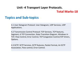
  • 1. Unit -4 Transport Layer Protocols. Total Marks-18 Topics and Sub-topics 4.1 User Datagram Protocol: User Datagram, UDP Services, UDP Applications. 4.2 Transmission Control Protocol: TCP Services, TCP features, Segment, A TCP Connection, State Transition Diagram, Windows in TCP, Flow Control, Error Control, TCP Congestion Control,TCP timers, Options. 4.3 SCTP: SCTP Services, SCTP features, Packet Format, An SCTP Association, Flow control, Error Control.
  • 2. • Transport Layer: • The Transport layer is the layer-4 of the OSI reference model. The transport layer is mainly responsible for the process-to-process delivery of the entire message. A process is basically an application program that is running on the host. • The basic function of the Transport layer is to accept data from the layer above, split it up into smaller units, pass these data units to the Network layer, and ensure that all the pieces arrive correctly at the other end. • Functions of Transport Layer 1. Service Point Addressing: Transport Layer header includes service point address which is the port address. This layer gets the message to the correct process on the computer unlike Network Layer, which gets each packet to the correct computer.
  • 3. • Functions of Transport Layer: 2. Segmentation and Reassembling: A message is divided into segments(that are transmittable); each segment contains a sequence number, which enables this layer in reassembling the message. The message is reassembled correctly upon arrival at the destination and replaces packets that were lost in transmission. 3. Connection Control: It includes 2 types: – Connectionless Transport Layer: Each segment is considered as an independent packet and delivered to the transport layer at the destination machine. – Connection-Oriented Transport Layer: Before delivering packets, the connection is made with the transport layer at the destination machine. 4. Flow Control: In this layer, flow control is performed end to end rather than across a single link. 5. Error Control: Error Control is performed end to end in this layer to ensure that the complete message arrives at the receiving transport layer without any error. Error Correction is done through retransmission.
  • 4. • Transport Layer Protocol: • Transport Layer Protocol 1. TCP (Transmission Control Protocol) 2. UDP (User Datagram Protocol) 3. SCTP (Stream Control Transmission Protocol) 4.1 UDP: • It is the simplest transport layer protocol. • It has been designed to send data packets over the Internet. • It simply takes the datagram from the network layer, attaches its header and sends it to the user. • Need of UDP- • TCP proves to be an overhead for certain kinds of applications. • The Connection Establishment Phase, Connection Termination Phase etc of TCP are time consuming. • To avoid this overhead, certain applications which require fast speed and less overhead use UDP.
  • 5. 4.1 UDP (User Datagram Protocol): Continue………. 4.1.1 Characteristics / Features of UDP- 1. It is a connectionless protocol. 2. It is a stateless protocol. 3. It is an unreliable protocol. 4. It is a fast protocol. 5. It offers the minimal transport service. 6. It is almost a null protocol. 7. It does not guarantee in order delivery. 8. It does not provide congestion control mechanism. 9. It is a good protocol for data flowing in one direction.
  • 6. • UDP (User Datagram Protocol) (Continue….) 4.1.2 UDP Datagram: • UDP Header:
  • 7. • UDP (User Datagram Protocol) (Continued….) 1. Source Port- • Source Port is a 16 bit field. • It identifies the port of the sending application. 2. Destination Port- • Destination Port is a 16 bit field. • It identifies the port of the receiving application. 3. Length- • Length is a 16 bit field. • It identifies the combined length of UDP Header and Encapsulated data. Length = Length of UDP Header + Length of encapsulated data 4. Checksum- • Checksum is a 16 bit field used for error control. • It is calculated on UDP Header, encapsulated data and IP pseudo header. • Checksum calculation is not mandatory in UDP.
  • 8. • UDP (User Datagram Protocol) (Continued….) 4.1.3 UDP Services / Operations: 1. Connectionless Services : • The User datagram protocol offers Connectionless Services which simply means that each user datagram that is sent by the UDP is an independent datagram. • In different datagrams, there is no relationship, even if they are coming from the same source process and also going to the same destination program. • User datagrams are not numbered, there is no connection establishment and no connection termination. • Each datagram mainly travels through different paths. 2. Flow Control and Error Control : • User datagram is a very simple and unreliable transport protocol. I • t does not provide any flow control mechanism and hence there is no window mechanism. Due to which the receiver may overflow with the incoming messages.
  • 9. • UDP (User Datagram Protocol) (Continued….) • No error control mechanism is provided by UDP except checksum. Due to which the sender does not know if any message is has been lost or duplicated. • As there is a lack of flow control and error control it means that the process that uses the UDP should provide these mechanisms. 3. Encapsulation and decapsulation: • In order to send the message from one process to another, the user datagram protocol encapsulates and decapsulates the message in the form of an IP datagram. 4. Queuing: • In UDP, queues are associated with ports. At the client site, when a process starts, it requests a port number from the operating system. • Some implementations create both an incoming and an outgoing queue associated with each process. Other implementations create only an incoming queue associated with each process.
  • 10. • UDP (User Datagram Protocol) (Continued….) 5. Process to Process Communication: • UDP provides process to process communication using sockets, a combination of IP addresses and port numbers. • Well known port numbers used by UDP are as follows: 6. Multiplexing and Demultiplexing:
  • 11. • UDP (User Datagram Protocol) (Continued….) 4.1.4 Applications Using UDP- • Applications which require one response for one request use UDP. Example- DNS. • Routing Protocols like RIP and OSPF use UDP because they have very small amount of data to be transmitted. • Trivial File Transfer Protocol (TFTP) uses UDP to send very small sized files. • Broadcasting and multicasting applications use UDP. • Streaming applications like multimedia, video conferencing etc use UDP since they require speed over reliability. • Real time applications like chatting and online games use UDP. • Management protocols like SNMP (Simple Network Management Protocol) use UDP. • Bootp / DHCP uses UDP. • Other protocols that use UDP are- Kerberos, Network Time Protocol (NTP), Network News Protocol (NNP), Quote of the day protocol etc.
  • 12. 4. 2 TCP- (Transmission Control Protocol) • It is a transport layer protocol. • It has been designed to send data packets over the Internet. • It establishes a reliable end to end connection before sending any data. 4.2.1 Characteristics Of TCP: 1. TCP is a reliable protocol. • This is because- • It guarantees the delivery of data packets to its correct destination. • After receiving the data packet, receiver sends an acknowledgement to the sender. • It tells the sender whether data packet has reached its destination safely or not. • TCP employs retransmission to compensate for packet loss.
  • 13. • TCP (Continued…) 2. TCP is a connection oriented protocol. • This is because- • TCP establishes an end to end connection between the source and destination. • The connection is established before exchanging the data. • The connection is maintained until the application programs at each end finishes exchanging the data. 3. TCP handles both congestion and flow control. • TCP handles congestion and flow control by controlling the window size. • TCP reacts to congestion by reducing the sender window size. 4. TCP ensures in-order delivery. • TCP ensures that the data packets get deliver to the destination in the same order they are sent by the sender. • Sequence Numbers are used to coordinate which data has been transmitted and received. 5. TCP connections are full duplex. • TCP connection allows to send data in both the directions at the same time. • So, TCP connections are Full Duplex.
  • 14. • TCP (Continued…) 6. TCP works in collaboration with Internet Protocol. • A TCP connection is uniquely identified by using- • Combination of port numbers and IP Addresses of sender and receiver. • IP Addresses indicate which systems are communicating. • Port numbers indicate which end to end sockets are communicating. • Port numbers are contained in the TCP header and IP Addresses are contained in the IP header. • TCP segments are encapsulated into an IP datagram. • So, TCP header immediately follows the IP header during transmission. 7. TCP can use both selective & cumulative acknowledgements. • TCP uses a combination of Selective Repeat and Go back N protocols. • In TCP, sender window size = receiver window size. • In TCP, out of order packets are accepted by the receiver. • When receiver receives an out of order packet, it accepts that packet but sends an acknowledgement for the expected packet. • Receiver may choose to send independent acknowledgements or cumulative acknowledgement. • To sum up, TCP is a combination of 75% SR protocol and 25% Go back N protocol.
  • 15. • TCP (Continued…) 8. TCP is a byte stream protocol. • Application layer sends data to the transport layer without any limitation. • TCP divides the data into chunks where each chunk is a collection of bytes. • Then, it creates a TCP segment by adding IP header to the data chunk. • TCP segment = TCP header + Data chunk. 9. TCP provides error checking & recovery mechanism. • TCP provides error checking and recovery using three simple techniques: 1. Checksum 2. Acknowledgement 3. Retransmission
  • 16. 4.2.2 TCP Segment and TCP Header: • The following diagram represents the TCP Segment and Header format- Header Data
  • 17. • TCP Header:(Continued….) 1. Source Port- • Source Port is a 16 bit field. • It identifies the port of the sending application. 2. Destination Port- • Destination Port is a 16 bit field. • It identifies the port of the receiving application. NOTE • It is important to note- • A TCP connection is uniquely identified by using- • Combination of port numbers and IP Addresses of sender and receiver • IP Addresses indicate which systems are communicating. • Port numbers indicate which end to end sockets are communicating.
  • 18. • TCP Header:(Continued….) 3. Sequence Number- • Sequence number is a 32 bit field. • TCP assigns a unique sequence number to each byte of data contained in the TCP segment. • This field contains the sequence number of the first data byte. 4. Acknowledgement Number- • Acknowledgment number is a 32 bit field. • It contains sequence number of the data byte that receiver expects to receive next from the sender. • It is always sequence number of the last received data byte incremented by 1. 5. Header Length- • Header length is a 4 bit field. • It contains the length of TCP header. • It helps in knowing from where the actual data begins. • Minimum and Maximum Header length- • The length of TCP header always lies in the range- [20 bytes , 60 bytes]
  • 19. • TCP Header:(Continued….) • The initial 5 rows of the TCP header are always used. • So, minimum length of TCP header = 5 x 4 bytes = 20 bytes. • The size of the 6th row representing the Options field vary. • The size of Options field can go up to 40 bytes. • So, maximum length of TCP header = 20 bytes + 40 bytes = 60 bytes. • Concept of Scaling Factor- • Header length is a 4 bit field. • So, the range of decimal values that can be represented is [0, 15]. • But the range of header length is [20, 60]. • So, to represent the header length, we use a scaling factor of 4. • In general, Header length = Header length field value x 4 bytes • Examples- • If header length field contains decimal value 5 (represented as 0101), then- Header length = 5 x 4 = 20 bytes • If header length field contains decimal value 10 (represented as 1010), then- Header length = 10 x 4 = 40 bytes • If header length field contains decimal value 15 (represented as 1111), then- Header length = 15 x 4 = 60 bytes
  • 20. • TCP Header:(Continued….) 6. Reserved Bits- • The 6 bits are reserved. • These bits are not used. 7. Control Field- This field defines 6 different control bits or flags as shown in Figure 4.2.2. One or more of these bits can be set at a time. Control field : URG: Urgent pointer is valid. ACK: Acknowledgment is valid. PSH: Request for push. RST: Reset the connection. SYN: Synchronize sequence numbers FIN: Terminate the connection. Figure 4.2.2 Flags in TCP Header URG ACK PSH RST SYN FIN
  • 21. • TCP Header:(Continued….) • Flag Description URG The value of the urgent pointer field is valid. ACK The value of the acknowledgment field is valid PSH Push the data. RST Reset the connection SYN Synchronize sequence numbers during connection. FIN Terminate the connection
  • 22. • TCP Header:(Continued….) 8. Window Size- • Window size is a 16 bit field. • It contains the size of the receiving window of the sender. • It advertises how much data (in bytes) the sender can receive without acknowledgement. • Thus, window size is used for Flow Control. NOTE • It is important to note- • The window size changes dynamically during data transmission. • It usually increases during TCP transmission up to a point where congestion is detected. • After congestion is detected, the window size is reduced to avoid having to drop packets.
  • 23. • TCP Header:(Continued….) 9. Checksum- • Checksum is a 16 bit field used for error control. • It verifies the integrity of data in the TCP payload. • Sender adds CRC checksum to the checksum field before sending the data. • Receiver rejects the data that fails the CRC check. 10. Urgent Pointer- • Urgent pointer is a 16 bit field. • It indicates how much data in the current segment counting from the first data byte is urgent. • Urgent pointer added to the sequence number indicates the end of urgent data byte. • This field is considered valid and evaluated only if the URG bit is set to 1.
  • 24. • TCP Header:(Continued….) 11. Options- • Options field is used for several purposes. • The size of options field vary from 0 bytes to 40 bytes. • Options field is generally used for the following purposes- 1. Time stamp 2. Window size extension 3. Parameter negotiation 4. Padding
  • 25. • 4.2.3 Three Way Handshake/TCP connection Establishment • Three Way Handshake is a process used for establishing a TCP connection. Consider- • Client wants to establish a connection with the server. • Before Three Way Handshake, both client and server are in closed state. • TCP Handshake involves the following steps in establishing the connection- Step-01: SYN- For establishing a connection, • Client sends a request segment to the server. • Request segment consists only of TCP Header with an empty payload. • Then, it waits for a reply segment from the server.
  • 26. • Three Way Handshake/TCP connection (Continued….) • Request segment contains the following information in TCP header- 1. Initial sequence number 2. SYN bit set to 1 3. Maximum segment size 4. Receiving window size 1. Initial Sequence Number- • Client sends the initial sequence number to the server. • It is contained in the sequence number field. • It is a randomly chosen 32 bit value. 2. SYN Bit Set To 1- Client sets SYN bit to 1 which indicates the server- • This segment contains the initial sequence number used by the client. • It has been sent for synchronizing the sequence numbers.
  • 27. • Three Way Handshake/TCP connection (Continued….) 3. Maximum Segment Size (MSS)- • Client sends its MSS to the server. • It dictates the size of the largest data chunk that client can send and receive from the server. • It is contained in the Options field. 4. Receiving Window Size- • Client sends its receiving window size to the server. • It dictates the limit of unacknowledged data that can be sent to the client. • It is contained in the window size field. Step-02: SYN + ACK- After receiving the request segment, • Server responds to the client by sending the reply segment. • It informs the client of the parameters at the server side.
  • 28. • Three Way Handshake/TCP connection (Continued….) • Reply segment contains the following information in TCP header- 1. Initial sequence number 2. SYN bit set to 1 3. Maximum segment size 4. Receiving window size 5. Acknowledgment number 6. ACK bit set to 1 1. Initial Sequence Number- • Server sends the initial sequence number to the client. • It is contained in the sequence number field. • It is a randomly chosen 32 bit value. 2. SYN Bit Set To 1- • Server sets SYN bit to 1 which indicates the client- • This segment contains the initial sequence number used by the server. • It has been sent for synchronizing the sequence numbers.
  • 29. • Three Way Handshake/TCP connection (Continued….) 3. Maximum Segment Size (MSS)- • Server sends its MSS to the client. • It dictates the size of the largest data chunk that server can send and receive from the client. • It is contained in the Options field. 4. Receiving Window Size- • Server sends its receiving window size to the client. • It dictates the limit of unacknowledged data that can be sent to the server. • It is contained in the window size field. 5. Acknowledgement Number- • Server sends the initial sequence number incremented by 1 as an acknowledgement number. • It dictates the sequence number of the next data byte that server expects to receive from the client. 6. ACK Bit Set To 1- • Server sets ACK bit to 1. • It indicates the client that the acknowledgement number field in the current segment is valid.
  • 30. • Three Way Handshake/TCP connection (Continued….) Step-03: ACK- • After receiving the reply segment, • Client acknowledges the response of server. • It acknowledges the server by sending a pure acknowledgement. With these, a Full Duplex connection is established. Important Points- Point-01: In step-01 and step-02- • The connection parameters are established for the first side. • They are acknowledged by the second side. In step-02 and step-03- • The connection parameters are established for the second side. • They are acknowledged by the first side.
  • 31. • 4.2.4 Four Way Handshake/TCP connection Release: • Suppose, the client needs to send some data to the server, it will be sent through a TCP. • TCP create a connection between the client and the server. Once the connection is successfully established and the data is transferred to the server. Thus, the next step will be to close the connection. • To terminate an established TCP connection, TCP uses Four Way Handshake method. • The following 4 TCP packets are needed to be exchanged. 1. Host A → Host B: FIN flag set. 2. Host B → Host A: ACK flag set. 3. Host B → Host A: FIN flag set. 4. Host A → Host B: ACK flag set.
  • 32. • Four Way Handshake/TCP connection Release: (Continue….) • These 4 steps are known as a TCP 4-way handshake, which is necessary to terminate a TCP connection. • For the termination of the established TCP connection, the following steps are necessary for the process. Which are given down below: Step 1: Firstly, from one side of the connection, either from the client or the server the FIN flag will be sent as the request for the termination of the connection. Step 2: In the second step, whoever receives the FIN flag will then be sending an ACK flag as the acknowledgment for the closing request to the other side. Step3 : And, at the Later step, the server will also send a FIN flag as the closing signal to the other side. Step 4: In the final step, the TCP, who received the final FIN flag, will be sending an ACK flag as the final Acknowledgement for the suggested connection closing.
  • 33. • Four Way Handshake/TCP connection Release: (Continue….) • Since the Four main steps are required to close an active connection, so, it is called a four-way handshake. The process is as shown in following figure. Figure: Four Way Handshake in TCP
  • 34. Q. Explain what happens when 2 hosts simultaneously try to establish a connection in tcp. • If two hosts try to establish a connection simultaneously between the same two sockets, then the events sequence is demonstrated in the figure under such circumstances. Only one connection is established. It cannot select both the links because their endpoints identify connections.
  • 35. 4.2.5 TCP State Transition Diagram: • To observe the events happening during connection establishment, connection termination, and data transfer, TCP is specified as the finite state machine (FSM) as shown in Figure 4.2.5.1. • Here two FSMs used by the TCP client and server combined in one diagram. • The rounded-corner rectangles represent the states. The transition from one state to another is shown using directed lines. Each line has two strings separated by a slash. The first string is the input, what TCP receives. The second is the output, what TCP sends. • The dotted black lines in the figure represent the transition that a server normally goes through; the solid black lines show the transitions that a client normally goes through. In some situations, a server transitions through a solid line or a client transitions through a dotted line.
  • 36. 4.2.5 TCP State Transition Diagram: (Continue……) • The colored lines show special situations. The rounded-corner rectangle marked ESTABLISHED has two sets of states, a set for the client and another for the server, that are used for flow and error control. • The total eleven states in such a state machine are given in following table. Sr. No. State Description 1 CLOSED No connection exists 2 LISTEN Passive open received; waiting for SYN 3 SYN-SENT SYN sent; waiting for ACK 4 SYN-RCVD SYN + ACK sent; waiting for ACK 5 ESTABLISHED Connection established; data transfer in progress 6 FIN-WAIT-1 First FIN sent; waiting for ACK 7 FIN-WAIT-2 ACK to first FIN received; waiting for second FIN 8 CLOSE-WAIT First FIN received, ACK sent; waiting for application to close. 9 TIME-WAIT Second FIN received, ACK sent; waiting for 2MSL time-out. 10 LAST-ACK Second FIN sent; waiting for ACK. 11 CLOSING Both sides decided to close simultaneous.
  • 37. 4.2.5 TCP State Transition Diagram: (Continue……) Figure 4.2.5.1 TCP State Transition Diagram.
  • 38. 4.2.5 TCP State Transition Diagram: (Continue……) • Consider the scenario. Figure 4.2.5.2 shows the state transition diagram for this scenario. The client process issues an active open command to its TCP to request a connection to a specific socket address. • TCP sends a SYN segment and moves to the SYN-SENT state. • After receiving the SYN +ACK segment, TCP sends an ACK segment and goes to the ESTABLISHED state. Data are transferred, possibly in both directions, and acknowledged. • When the client process has no more data to send, it issues a command called an active close. The TCP sends a FIN segment and goes to the FINWAIT1 state. When it receives the ACK segment, it goes to the FIN-WAIT-2 state. • When the client receives a FIN segment, it sends an ACK segment and goes to the TIME-WAIT state. The client remains in this state for 2 MSL .MSL is the maximum time a TCP segment is expected to live, or stay in the network. When the corresponding timer expires, the client goes to the CLOSED state. The server process issues a passive open command. The server TCP goes to the LISTEN state and remains there passively until it receives a SYN segment.
  • 39. 4.2.5 TCP State Transition Diagram: (Continue……) • The TCP then sends a SYN +ACK segment and goes to the SYN-RCVD state, waiting for the client to send an ACK segment. After receiving the ACK segment, TCP goes to the ESTABLISHED state, where data transfer can take place. TCP remains in this state until it receives a FIN segment from the client signifying that there are no more data to be exchanged and the connection can be closed.The server, upon receiving the FIN segment, sends all queued data to the server with a virtual EOF marker, which means that the connection must be closed. It sends an ACK segment and goes to the CLOSEWAIT state, but postpones acknowledging the FIN segment received from the client until it receives a passive close command from its process. After receiving the passive close command, the server sends a FIN segment to the client and goes to the LASTACK state, waiting for the final ACK. When the ACK segment is received from the client,the server goes to the CLOSE state.
  • 40. 4.2.5 TCP State Transition Diagram: (Continue……) • Figure 4.2.5.2 Separate TCP State Transition Diagram for Client and Server.
  • 41. 4.2.6 TCP Services 1. Process-to-Process Communication: • TCP provides process-to-process communication i.e. the transfer of data takes place between individual processes executing on end systems. This is done using port numbers or port addresses. • Port numbers are 16-bit long that help to identify which process is sending or receiving data on a host. The following table 4.2.4.1 lists some well-known port numbers used by TCP. 2. Stream Delivery Service: • TCP is a stream-oriented protocol. TCP, allows the sending process to deliver data as a stream of bytes and allows the receiving process to obtain data as a stream of bytes. • TCP creates an environment in which the two processes seem to be connected by an imaginary "tube" that carries their data across the Internet. This imaginary environment is shown in the following figure 4.2.4.1. The sending process produces (writes to) the stream of bytes, and the receiving process consumes (reads from) them.
  • 42. 4.2.6 TCP Services (Continue…..) • Table 4.2.4.1 Well Known Ports of TCP
  • 43. 4.2.6 TCP Services (Continue…..) Figure 4.2.4.1 Stream Delivery
  • 44. 4.2.6 TCP Services (Continue…..) 3. Sending and Receiving Buffers: • Because the sending and the receiving processes may not write or read data at the same speed, TCP needs buffers for storage. • There are two buffers, the sending buffer and the receiving buffer, one for each direction and these buffers are also necessary for flow and error control mechanisms used by TCP. 4. Bytes and Segments: • The buffering handles the disparity between the speed of the producing and consuming processes, we need one more step before we can send data. • The IP layer, as a service provider for TCP, needs to send data in packets, not as a stream of bytes. At the transport layer, TCP groups a number of bytes together into a packet called a segment. TCP adds a header to each segment (for control purposes) and delivers the segment to the IP layer for transmission.
  • 45. 4.2.6 TCP Services (Continue…..) • The segments are encapsulated in IP datagrams and transmitted. • This entire operation is transparent to the receiving process. The segments may be received out of order, lost, or corrupted and resent. • All these are handled by TCP with the receiving process unaware of any activities. 5. Full-Duplex Communication: • TCP offers full-duplex service, in which data can flow in both directions at the same time. • Each TCP then has a sending and receiving buffer, and segments move in both directions. 6. Connection-Oriented Service: • TCP is a connection-oriented protocol. When a process at site A wants to send and receive data from another process at site B, the following occurs:
  • 46. 4.2.6 TCP Services (Continue…..) 1. The two TCPs establish a connection between them. 2. Data are exchanged in both directions. 3. The connection is terminated. (Note: This is a logical connection, not physical). 7. Reliable Service: • TCP is a reliable transport protocol. It uses an acknowledgment mechanism to check the safe and sound arrival of data. • TCP uses checksum for error control.
  • 47. 4.2.7 Flow Control in TCP: • In flow control TCP will ensure that a sender is not overwhelming a receiver by sending packets faster than it can consume. • Flow control regulates the amount of data a source can send before receiving an acknowledgment from the destination. Figure Flow Control in TCP
  • 48. 4.2.7 Flow Control in TCP: (Continue…..) • In communication at the transport layer, we are dealing with four entities: sender process, sender transport layer, receiver transport layer, and receiver process. 1. The sending process at the application layer is only a producer. It produces message chunks and pushes them to the transport layer. 2. The sending transport layer has a double role: it is both a consumer and the producer. It consumes the messages pushed by the producer. It encapsulates the messages in packets and pushes them to the receiving transport layer. 3. The receiving transport layer has also a double role: it is the consumer for the packets received from the sender. It is also a producer; it needs to decapsulate the messages and deliver them to the application layer. 4. The last delivery, however, is normally a pulling delivery; the transport layer waits until the application-layer process asks for messages.
  • 49. 4.2.8 Error Control in TCP: • TCP is a reliable transport layer protocol. This means that an application program that delivers a stream of data to TCP relies on TCP to deliver the entire stream to the application program on the other end in order, without error, and without any part lost or duplicated. • TCP protocol has methods for finding out corrupted segments, missing segments, out-of-order segments and duplicated segments. • Error control in TCP is mainly done through the use of three simple techniques : 1. Checksum – Every segment contains a checksum field which is used to find corrupted segments. If the segment is corrupted, then that segment is discarded by the destination TCP and is considered lost. 2. Acknowledgement – TCP has another mechanism called acknowledgement to affirm that the data segments have been delivered. Control segments that contain no data but have sequence numbers will be acknowledged as well but ACK segments are not acknowledged.
  • 50. 4.2.8 Error Control in TCP: (Continue…….) 3. Retransmission – When a segment is missing, delayed to deliver to a receiver, corrupted when it is checked by the receiver then that segment is retransmitted again. • Segments are retransmitted only during two events: a) When the sender receives three duplicate acknowledgements (ACK) or b) When a retransmission timer expires. i) Retransmission after RTO: TCP always preserves one Retransmission Time-Out (RTO) timer for all sent but not acknowledged segments. • When the timer runs out of time, the earliest segment is retransmitted. Here no timer is set for acknowledgement. • In TCP, the RTO value is dynamic in nature and it is updated using the Round Trip Time (RTT) of segments. • RTT is the time duration needed for a segment to reach the receiver and an acknowledgement to be received by the sender.
  • 51. 4.2.8 Error Control in TCP: (Continue…….) ii) Retransmission after Three duplicate ACK segments: • RTO method works well when the value of RTO is small. If it is large, more time is needed to get confirmation about whether a segment has been delivered or not. • Sometimes one segment is lost and the receiver receives so many out-of- order segments that they cannot be saved. • In order to solve this situation, three duplicate acknowledgement method is used and missing segment is retransmitted immediately instead of retransmitting already delivered segment. • This is a fast retransmission because it makes it possible to quickly retransmit lost segments instead of waiting for timer to end.