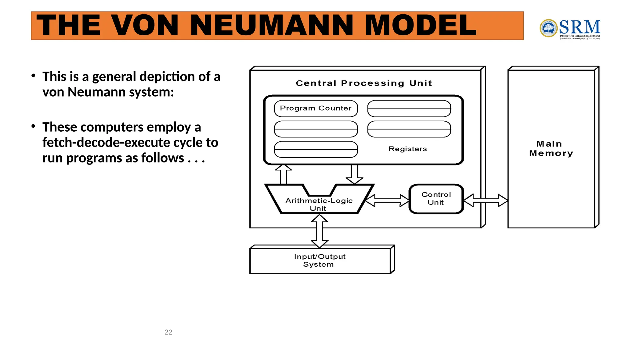
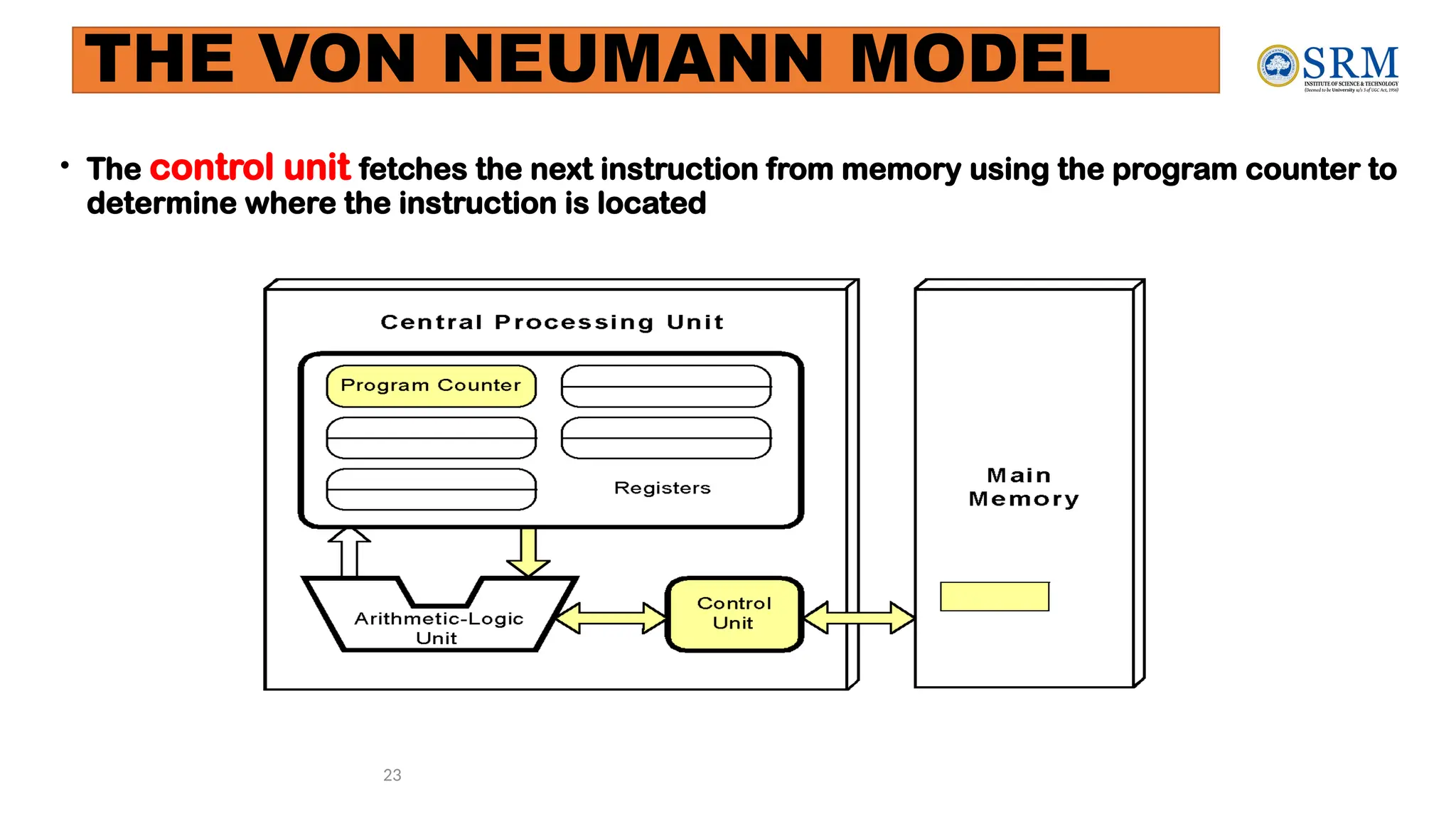
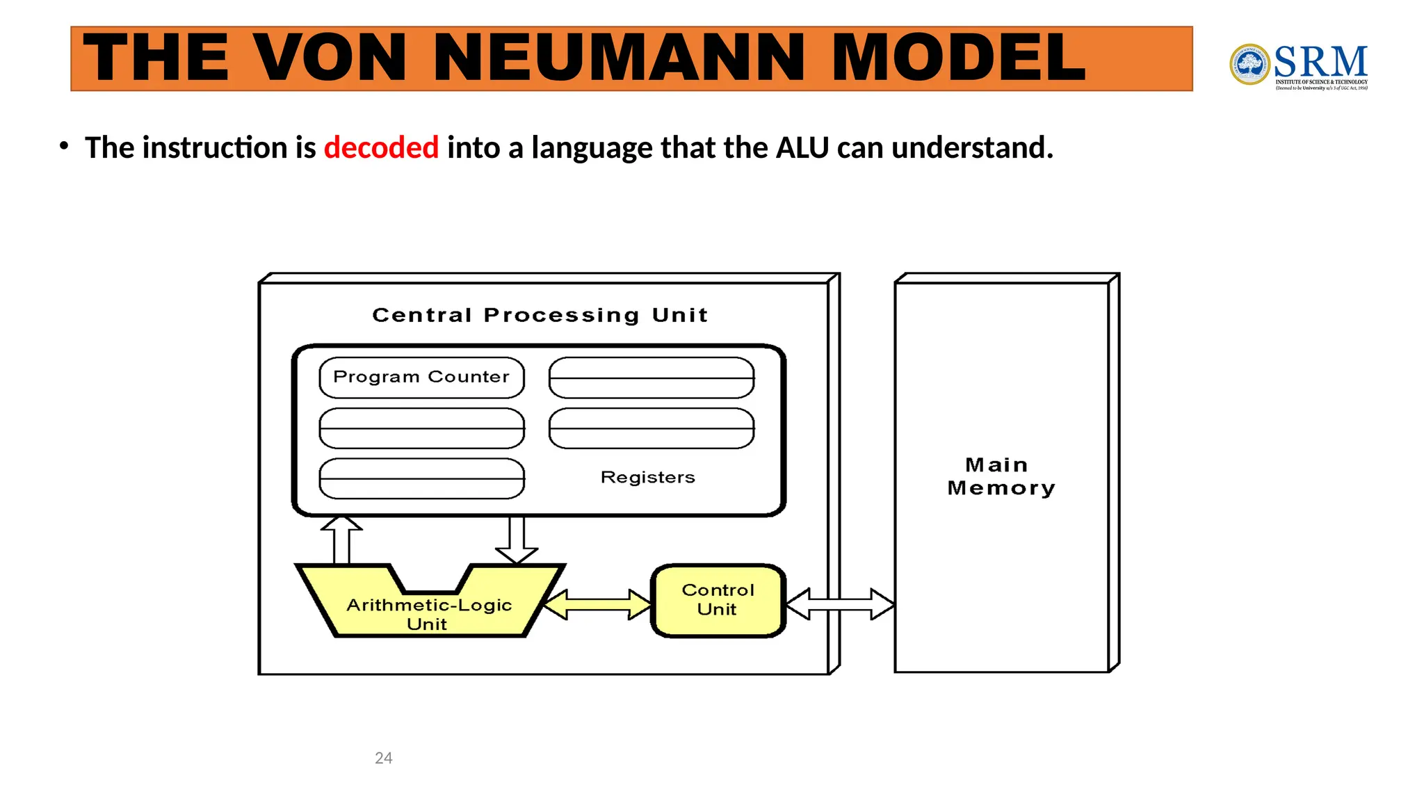
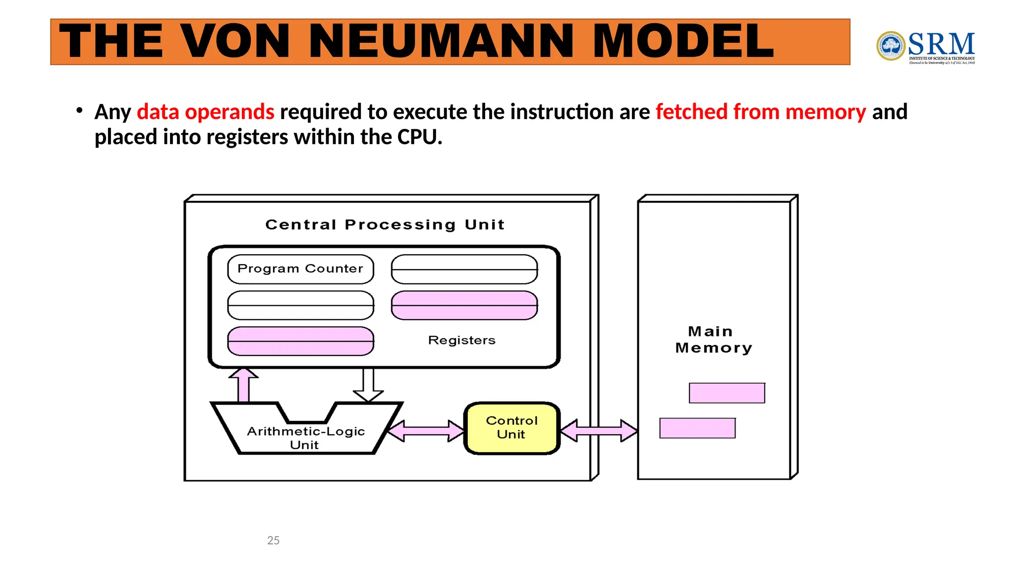
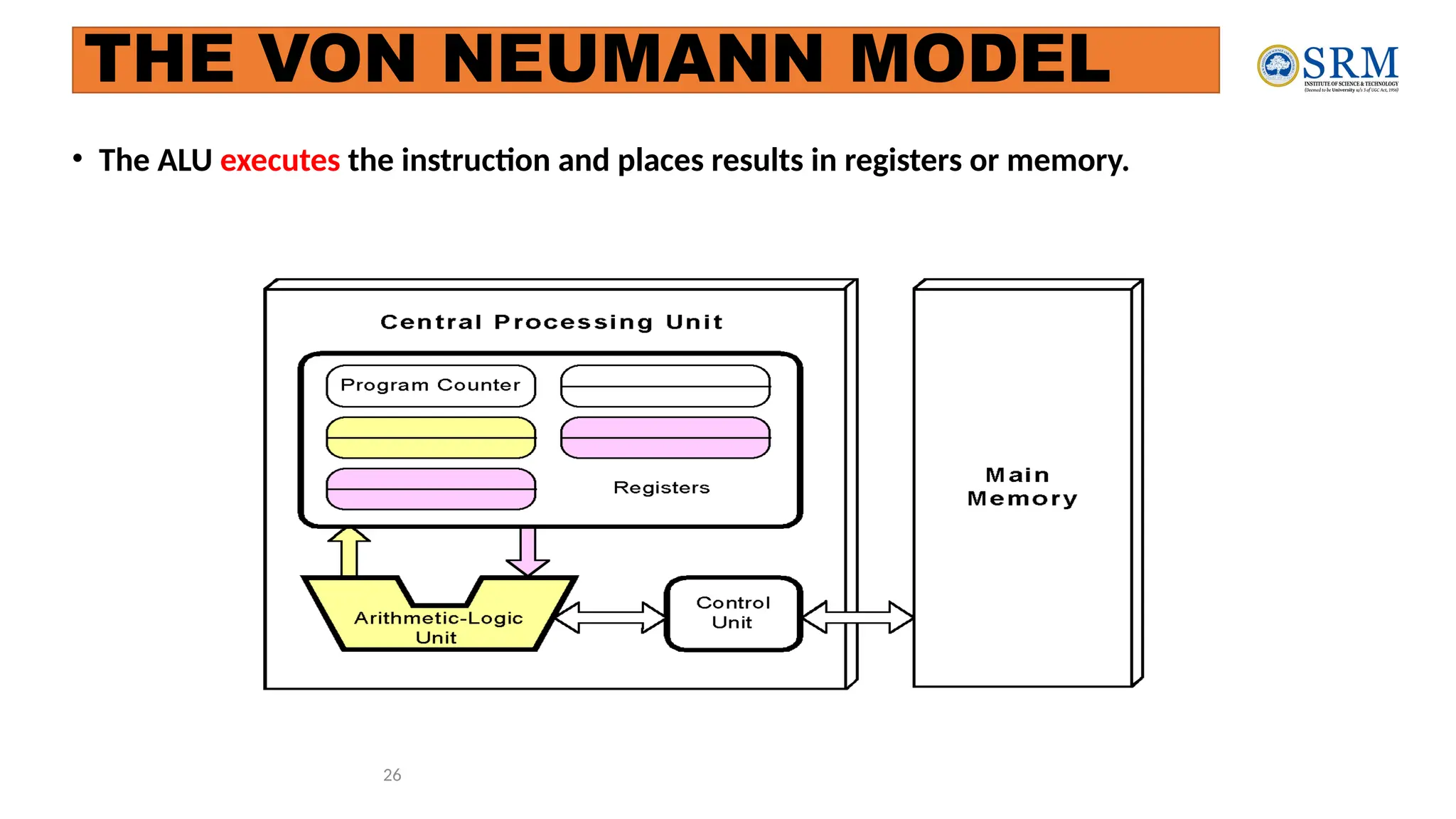
21CSS201T
COMPUTER ORGANIZATION AND
ARCHITECTURE
UNIT-1
2
Know the difference between computer organization and computer
architecture.
Understand units of measure common to computer systems
Appreciate the evolution of computers.
Understand the computer as a layered system.
Be able to explain the von Neumann architecture and the function of basic
computer components.
Computer Architecture
Objectives
3
• A modern computer is an electronic, digital, general purpose computing machine
that automatically follows a step-by-step list of instructions to solve a problem. This
step-by step list of instructions that a computer follows is also called an algorithm or
a computer program.
• Why to study computer organization and architecture?
• Design better programs, including system software such as compilers, operating
systems, and device drivers.
• Optimize program behavior.
• Evaluate (benchmark) computer system performance.
• Understand time, space, and price tradeoffs.
• Computer organization
• Encompasses all physical aspects of computer systems.
• E.g., circuit design, control signals, memory types.
• How does a computer work?
COMPUTER ARCHITECTURE AND ORGANIZATION OVERVIEW
Focuses on the structure(the way in which the components are interrelated) and
behavior of the computer system and refers to the logical aspects of system
implementation as seen by the programmer
Computer architecture includes many elements such as
instruction sets and formats, operation codes, data types, the number and types of
registers, addressing modes, main memory access methods, and various I/O
mechanisms.
The architecture of a system directly affects the logical execution of programs.
The computer architecture for a given machine is the combination of its hardware
components plus its instruction set architecture (ISA).
The ISA is the interface between all the software that runs on the machine and the hard
Studying computer architecture helps us to answer the question: How do I design
a computer?
4
COMPUTER ARCHITECTURE AND ORGANIZATION OVERVIEW
5
In the case of the IBM, SUN and Intel ISAs, it is possible to purchase processors
which execute the same instructions from more than one manufacturer
All these processors may have quite different internal organizations but they all
appear identical to a programmer, because their instruction sets are the same
Organization & Architecture enables a family of computer models
 Same Architecture, but with differences in Organization
 Different price and performance characteristics
When technology changes, only organization changes.
This gives code compatibility (backwards)
COMPUTER ARCHITECTURE AND ORGANIZATION OVERVIEW
6
COMPUTER COMPONENTS
At the most basic level, a computer is a device consisting of 3 pieces
A processor to interpret and execute programs
A memory ( Includes Cache, RAM, ROM) to store both data and
program instructions
A mechanism for transferring data to and from the outside world.
 I/O to communicate between computer and the world
 Bus to move info from one computer component to another
7
Contd..
• Computers with large main memory capacity can run larger programs with
greater speed than computers having small memories.
• RAM is an acronym for random access memory. Random access means that
memory contents can be accessed directly if you know its location.
• Cache is a type of temporary memory that can be accessed faster than RAM.
8
1ST
GENERATION COMPUTERS
• Used vacuum tubes for logic and storage (very little storage available)
• A vacuum-tube circuit storing 1 byte
• Programmed in machine language
• Often programmed by physical connection (hardwiring)
• Slow, unreliable, expensive
• The ENIAC – often thought of as the first programmable electronic computer
– 1946
• 17468 vacuum tubes, 1800 square feet, 30 tons
9
2nd
Generation Computers
• Transistors replaced vacuum tubes
• Magnetic core memory introduced
• Changes in technology brought about cheaper and more reliable computers (vacuum
tubes were very unreliable)
• Because these units were smaller, they were closer together providing a speedup over
vacuum tubes
• Various programming languages introduced (assembly, high-level)
• Rudimentary OS developed
• The first supercomputer was introduced, CDC 6600 ($10 million)
10
3RD GENERATION COMPUTERS INTEGRATED CIRCUIT (IC)
The ability to place circuits onto silicon chips
• Replaced both transistors and magnetic core memory
• Result was easily mass-produced components reducing the cost of computer
manufacturing significantly
• Also increased speed and memory capacity
• Computer families introduced
• Minicomputers introduced
• More sophisticated programming languages and OS developed
• Popular computers included PDP-8, PDP-11, IBM 360 and Cray produced their
first supercomputer, Cray-1
• Silicon chips now contained both logic (CPU) and memory
• Large-scale computer usage led to time-sharing OS
11
4th
Generation Computers 1971-Present:
Microprocessors
• Miniaturization took over
• From SSI (10-100 components per chip) to
• MSI (100-1000), LSI (1,000-10,000), VLSI (10,000+)
• Thousands of ICs were built onto a single silicon chip(VLSI), which allowed
Intel, in 1971, to
• create the world’s first microprocessor, the 4004, which was a fully functional, 4-bit system
that ran at 108KHz.
• Intel also introduced the RAM chip, accommodating 4Kb of memory on a
single chip. This allowed computers of the 4th
generation to become smaller
and faster than their solid-state predecessors
• Computers also saw the development of GUIs, the mouse and handheld
devices
12
Through the principle of abstraction, we can imagine the machine to be built from
a hierarchy of levels, in which each level has a specific function and exists as a
distinct hypothetical Machine
Abstraction is the ability to focus on important aspects of a situation at a higher
level while ignoring the underlying complex details
We call the hypothetical computer at each level a virtual machine.
Each level’s virtual machine executes its own particular set of instructions, calling
upon machines at lower levels to carry out the tasks when necessary
The Computer Level Hierarchy
Level 6: The User Level
• Composed of applications and is the level with which everyone is most familiar.
• At this level, we run programs such as word processors, graphics packages, or games.
• The lower levels are nearly invisible from the User Level.
13
The Computer Level Hierarchy
Level 5: High-Level Language Level
• The level with which we interact when we write programs in languages such
as C, Pascal, Lisp, and Java
• These languages must be translated to a language the machine can understand.
(using compiler / interpreter)
• Compiled languages are translated into assembly language and then
assembled into machine code. (They are translated to the next lower level.)
• The user at this level sees very little of the lower levels
14
The Computer Level Hierarchy
15
Level 4: Assembly Language Level
• Acts upon assembly language produced from Level 5, as well as instructions
programmed directly at this level
• As previously mentioned, compiled higher-level languages are first translated to
assembly, which is then directly translated to machine language. This is a one-to-one
translation, meaning that one assembly language instruction is translated to exactly
one machine language instruction.
• By having separate levels, we reduce the semantic gap between a high-level
language and the actual machine language
The Computer Level Hierarchy
Level 3: System Software Level
• deals with operating system instructions.
• This level is responsible for multiprogramming, protecting memory,
synchronizing processes, and various other important functions.
• Often, instructions translated from assembly language to machine language are
passed through this level unmodified
16
The Computer Level Hierarchy
Level 2: Machine Level
• Consists of instructions (ISA)that are particular to the architecture of the
machine
• Programs written in machine language need no compilers, interpreters, or
assemblers
Level 1: Control Level
• A control unit decodes and executes instructions and moves data through the
system.
• Control units can be microprogrammed or hardwired
• A microprogram is a program written in a low-level language that is
implemented by the hardware.
• Hardwired control units consist of hardware that directly executes machine
instruction
17
The Computer Level Hierarchy
Level 0: Digital Logic Level
• This level is where we find digital circuits (the chips)
• Digital circuits consist of gates and wires.
• These components implement the mathematical logic of all other levels
18
The Computer Level Hierarchy
The Von Neumann Architecture
Named after John von Neumann, Princeton, he designed a computer architecture
whereby data and instructions would be retrieved from memory, operated on by an
ALU, and moved back to memory (or I/O)
This architecture is the basis for most modern computers (only parallel processors
and a few other unique architectures use a different model)
19
• There is a single pathway used to move both data and instructions between memory, I/O and CPU
• the pathway is implemented as a bus
• the single pathway creates a bottleneck
• known as the von Neumann bottleneck
• A variation of this architecture is the Harvard architecture which separates data and instructions
into two pathways
• Another variation, used in most computers, is the system bus version in which there are
different buses between CPU and memory and memory and I/O
20
The Von Neumann Architecture
Fetch-execute cycle
21
• The von Neumann architecture operates on the fetch-execute cycle
• Fetch an instruction from memory as indicated by the Program Counter
register
• Decode the instruction in the control unit
• Data operands needed for the instruction are fetched from memory
• Execute the instruction in the ALU storing the result in a register
• Move the result back to memory if needed
22
• This is a general depiction of a
von Neumann system:
• These computers employ a
fetch-decode-execute cycle to
run programs as follows . . .
THE VON NEUMANN MODEL
23
• The control unit fetches the next instruction from memory using the program counter to
determine where the instruction is located
THE VON NEUMANN MODEL
24
• The instruction is decoded into a language that the ALU can understand.
THE VON NEUMANN MODEL
25
• Any data operands required to execute the instruction are fetched from memory and
placed into registers within the CPU.
THE VON NEUMANN MODEL
26
• The ALU executes the instruction and places results in registers or memory.
THE VON NEUMANN MODEL
Non-Von Neumann Models
• Conventional stored-program computers have undergone many incremental
improvements over the years
• specialized buses
• floating-point units
• cache memories
• But enormous improvements in computational power require departure from the
classic von Neumann architecture
• Adding processors is one approach
27
• In the late 1960s, high-performance computer systems were equipped with dual
processors to increase computational throughput.
• In the 1970s supercomputer systems were introduced with 32 processors.
• Supercomputers with 1,000 processors were built in the 1980s.
• In 1999, IBM announced its Blue Gene system containing over 1 million
processors.
28
Non-Von Neumann Models
Introduction to Number System and
Logic Gates
Number Systems- Binary, Decimal, Octal, Hexadecimal
Codes- Grey, BCD,Excess-3,
ASCII, Parity
Binary Arithmetic- Addition, Subtraction, Multiplication, Division using
Sign Magnitude
1’s compliment, 2’s compliment,
BCD Arithmetic;
 Logic Gates-AND, OR, NOT, NAND,
NOR, EX-OR, EX-NOR
Chapter 1 30
Digital System
• Takes a set of discrete information inputs and discrete internal information
(system state) and generates a set of discrete information outputs.
System State
Discrete
Information
Processing
System
Discrete
Inputs Discrete
Outputs
Chapter 1 31
Types of Digital Systems
• No state present
• Combinational Logic System
• Output = Function(Input)
• State present
• State updated at discrete times
=> Synchronous Sequential System
• State updated at any time
=>Asynchronous Sequential System
• State = Function (State, Input)
• Output = Function (State)
or Function (State, Input)
Chapter 1 32
Digital System Example
A Digital Counter (e. g., odometer):
1 3
0 0 5 6 4
Count Up
Reset
Inputs: Count Up, Reset
Outputs: Visual Display
State: "Value" of stored digits
Synchronous or Asynchronous?
Chapter 1 33
A Digital Computer Example
Synchronous or
Asynchronous?
Inputs: Keyboard,
mouse, modem,
microphone
Outputs: CRT,
LCD, modem,
speakers
Memory
Control
unit Datapath
Input/Output
CPU
Chapter 1 34
Signal
• An information variable represented by physical quantity.
• For digital systems, the variable takes on discrete values.
• Two level, or binary values are the most prevalent values in digital systems.
• Binary values are represented abstractly by:
• digits 0 and 1
• words (symbols) False (F) and True (T)
• words (symbols) Low (L) and High (H)
• and words On and Off.
• Binary values are represented by values or ranges of values of physical
quantities
Chapter 1 35
Signal Examples Over Time
Analog
Asynchronous
Synchronous
Time
Continuous
in value &
time
Discrete in
value &
continuous
in time
Discrete in
value & time
Digital
Chapter 1 36
•What are other physical quantities represent 0 and
1?
• CPU Voltage
• Disk
• CD
• Dynamic RAM
Binary Values: Other Physical Quantities
Magnetic Field Direction
Surface Pits/Light
Electrical Charge
Chapter 1 37
Number Systems Representation
• Positive radix, positional number systems
• A number with radix r is represented by a string of digits:
An - 1An - 2 … A1A0 . A- 1 A- 2 … A- m + 1 A- m
in which 0 £ Ai < r and . is the radix point.
• The string of digits represents the power series:
( ) ( )
(Number)r =
å
å +
j = - m
j
j
i
i = 0
i r
A
r
A
(Integer Portion) + (Fraction Portion)
i = n - 1 j = - 1
Chapter 1 38
Number Systems – Examples
General Decimal Binary
Radix (Base) r 10 2
Digits 0 => r - 1 0 => 9 0 => 1
0
1
2
3
Powers of 4
Radix 5
-1
-2
-3
-4
-5
r0
r1
r2
r3
r4
r5
r -1
r -2
r -3
r -4
r -5
1
10
100
1000
10,000
100,000
0.1
0.01
0.001
0.0001
0.00001
1
2
4
8
16
32
0.5
0.25
0.125
0.0625
0.03125
Chapter 1 39
Special Powers of 2

210
(1024) is Kilo, denoted "K"
 220
(1,048,576) is Mega, denoted "M"

230
(1,073, 741,824)is Giga, denoted "G"
Chapter 1 40
• Useful for Base Conversion
Exponent Value Exponent Value
0 1 11 2,048
1 2 12 4,096
2 4 13 8,192
3 8 14 16,384
4 16 15 32,768
5 32 16 65,536
6 64 17 131,072
7 128 18 262,144
19 524,288
20 1,048,576
21 2,097,152
8 256
9 512
10 1024
Positive Powers of 2
Chapter 1 41
• To convert to decimal, use decimal arithmetic to form S
(digit × respective power of 2).
• Example:Convert 110102 to N10:
Converting Binary to Decimal
Chapter 1 42
• Method 1
• Subtract the largest power of 2 (see slide 14) that gives a
positive remainder and record the power.
• Repeat, subtracting from the prior remainder and recording
the power, until the remainder is zero.
• Place 1’s in the positions in the binary result corresponding
to the powers recorded; in all other positions place 0’s.
• Example: Convert 62510 to N2
Converting Decimal to Binary
Chapter 1 43
Commonly Occurring Bases
Name Radix Digits
Binary 2 0,1
Octal 8 0,1,2,3,4,5,6,7
Decimal 10 0,1,2,3,4,5,6,7,8,9
Hexadecimal 16 0,1,2,3,4,5,6,7,8,9,A,B,C,D,E,F
 The six letters (in addition to the 10
integers) in hexadecimal represent:
Chapter 1 44
Decimal
(Base 10)
Binary
(Base 2)
Octal
(Base 8)
Hexa decimal
(Base 16)
00 00000 00 00
01 00001 01 01
02 00010 02 02
03 00011 03 03
04 00100 04 04
05 00101 05 05
06 00110 06 06
07 00111 07 07
08 01000 10 08
09 01001 11 09
10 01010 12 0A
11 01011 13 0B
12 01100 14 0C
13 01101 15 0D
14 01110 16 0E
15 01111 17 0F
16 10000 20 10
• Good idea to memorize!
Numbers in Different Bases
Chapter 1 45
Conversion Between Bases
 Method 2
 To convert from one base to another:
1) Convert the Integer Part
2) Convert the Fraction Part
3) Join the two results with a radix point
Chapter 1 46
Conversion Details
• To Convert the Integral Part:
Repeatedly divide the number by the new radix and save the remainders. The
digits for the new radix are the remainders in reverse order of their
computation. If the new radix is > 10, then convert all remainders > 10 to
digits A, B, …
• To Convert the Fractional Part:
Repeatedly multiply the fraction by the new radix and save the integer digits
that result. The digits for the new radix are the integer digits in order of their
computation. If the new radix is > 10, then convert all integers > 10 to digits A,
B, …
Chapter 1 47
Example: Convert 46.687510 To Base 2
• Convert 46 to Base 2
• Convert 0.6875 to Base 2:
• Join the results together with the radix point:
Chapter 1 48
Additional Issue- Fractional Part
• Note that in this conversion, the fractional part became 0 as a result
of the repeated multiplications.
• In general, it may take many bits to get this to happen or it may
never happen.
• Example: Convert 0.6510 to N2
• 0.65 = 0.1010011001001 …
• The fractional part begins repeating every 4 steps yielding repeating 1001
forever!
• Solution: Specify number of bits to right of radix point and round or
truncate to this number.
Chapter 1 49
Checking the Conversion
•To convert back, sum the digits times their respective powers of r.
•From the prior conversion of 46.687510
1011102 = 1·32 + 0·16 +1·8 +1·4 + 1·2 +0·1
= 32 + 8 + 4 + 2
= 46
0.10112 = 1/2 + 1/8 + 1/16
= 0.5000 + 0.1250 + 0.0625
= 0.6875
Chapter 1 50
A Final Conversion Note
• You can use arithmetic in other bases if you are careful:
• Example: Convert 1011102 to Base 10 using binary arithmetic:
Step 1 101110 / 1010 = 100 r 0110
Step 2 100 / 1010 = 0 r 0100
Converted Digits are 01002 | 01102
or 4 6 10
Chapter 1 51
Binary Numbers and Binary Coding
• Flexibility of representation
• Within constraints below, can assign any binary combination (called a code
word) to any data as long as data is uniquely encoded.
• Information Types
• Numeric
• Must represent range of data needed
• Very desirable to represent data such that simple, straightforward computation for
common arithmetic operations permitted
• Tight relation to binary numbers
• Non-numeric
• Greater flexibility since arithmetic operations not applied.
• Not tied to binary numbers
Chapter 1 52
• Given n binary digits (called bits), a binary code is a mapping
from a set of represented elements to a subset of the 2n
binary
numbers.
• Example: A
binary code
for the seven
colors of the
rainbow
• Code 100 is
not used
Non-numeric Binary Codes
Binary Number
000
001
010
011
101
110
111
Color
Red
Orange
Yellow
Green
Blue
Indigo
Violet
Chapter 1 53
• Given M elements to be represented by a binary code, the minimum
number of bits, n, needed, satisfies the following relationships:
2n
> M > 2(n – 1)
n = log2 M where x , called the ceiling
function, is the integer greater than or equal to x.
• Example: How many bits are required to represent decimal digits
with a binary code?
Number of Bits Required
Chapter 1 54
Number of Elements Represented
• Given n digits in radix r, there are rn
distinct elements that can be
represented.
• But, you can represent m elements, m < rn
• Examples:
• You can represent 4 elements in radix r = 2 with n = 2 digits: (00, 01, 10, 11).
• You can represent 4 elements in radix r = 2 with n = 4 digits: (0001, 0010,
0100, 1000).
• This second code is called a "one hot" code.
Chapter 1 55
Binary Codes for Decimal Digits
Decimal 8,4,2,1 Excess3 8,4,-2,-1 Gray
0 0000 0011 0000 0000
1 0001 0100 0111 0100
2 0010 0101 0110 0101
3 0011 0110 0101 0111
4 0100 0111 0100 0110
5 0101 1000 1011 0010
6 0110 1001 1010 0011
7 0111 1010 1001 0001
8 1000 1011 1000 1001
9 1001 1100 1111 1000
 There are over 8,000 ways that you can chose 10 elements
from the 16 binary numbers of 4 bits. A few are useful:
Chapter 1 56
Binary Coded Decimal (BCD)
• The BCD code is the 8,4,2,1 code.
• This code is the simplest, most intuitive binary code for decimal
digits and uses the same powers of 2 as a binary number, but only
encodes the first ten values from 0 to 9.
• Example: 1001 (9) = 1000 (8) + 0001 (1)
• How many “invalid” code words are there?
• What are the “invalid” code words?
Chapter 1 57
• What interesting property is common to these two codes?
Excess 3 Code and 8, 4, –2, –1 Code
Decimal Excess 3 8, 4, –2, –1
0 0011 0000
1 0100 0111
2 0101 0110
3 0110 0101
4 0111 0100
5 1000 1011
6 1001 1010
7 1010 1001
8 1011 1000
9 1100 1111
21CSS201T-COA 58
GRAY CODE
• Gray code is the arrangement of binary number system such that each
incremental value can only differ by one bit.
• This code is also known as Reflected Binary Code (RBC), Cyclic
Code and Reflected Binary (RB). The reason for calling this code as
reflected binary code is the first N/2 values compared with those of the last
N/2 values in reverse order.
• In gray code when transverse from one step to another step the only one bit
will be change of the group. This means that the two adjacent code numbers
differ from each other by only one bit.
• It is popular for unit distance code but it is not use from arithmetic
operations. This code has some application like convert analog to digital,
error correction in digital communication.
21CSS201T-COA 59
Binary- Gray code conversion
• STEPS
• The most significant bit of gray code is equal to the first bit of the
given binary bit.
• The second bit of gray code will be exclusive-or (XOR) of the first
and second bit of the given binary bit.
• The third bit of gray code is equal to the exclusive-or (XOR) of the
second and third binary bits. For father gray code result this
process will be continuing.
21CSS201T-COA 60
Explanation
• The given binary digit is 01001
0 1 0 0 1 (Binary)
MSB LSB
Gray code Conversion
0, 0 1, 1 0,0 0, 0 1
0 , 1 , 1 , 0 , 1 (On concatening)
The gray code of the given binary code (01001)
=0 1 1 0 1 (One bit changed)
Truth Table of XOR
A B C
0 0 0
0 1 1
1 0 1
1 1 0
21CSS201T-COA 61
Example
• The gray code of the given binary code is (010.01)2 ??
• The first MSB bit of binary is same in the first bit of gray code. In this example
the binary bit is “0”. So, gray bit also “0”.
• Next gray bit is equal to the XOR of the first and the second binary bit. The first
bit is 0, and the second bit is 1. The bits are different so resultant gray bit will be
“1” (second gray codes bit)
• The XOR of the second and third binary bit. The second bit is 1 and third is 0.
These bits are again different so the resultant gray bit will be 1 (third gray codes
bit)
• Next we perform the XOR operation on third and fourth binary bit. The third bit
is 0, and the fourth bit is 0. The both bits are same than resultant gray codes will
be 0 (fourth gray codes bit).
• Take the XOR of the fourth and fifth binary bit. The fourth bit is 0 and fifth bit is
1. These bits are different than resultant gray codes will be 1 (fifth gray code bit)
• The result of binary to gray codes conversion is 01101.
21CSS201T-COA 62
GRAY CODE TABLE
The conversion in between decimal to gray and binary to gray code is
given below
Decimal
Number
Binary Number Gray Code
0 0000 0000
1 0001 0001
2 0010 0011
3 0011 0010
4 0100 0110
5 0101 0111
6 0110 0101
7 0111 0100
8 1000 1100
9 1001 1101
10 1010 1111
11 1011 1110
12 1100 1010
13 1101 1011
14 1110 1001
15 1111 1000
:
The gray code of the given binary code
(01001) =0 1 1 0 1. We can see one bit change
in the next incremental value.
21CSS201T-COA 63
• You can convert n bit (bnb(n-1)…b2b1b0) binary number to gray
code (gng(n-1)…g2g1g0). For most significant bit bn=gn, and rest of
the bit by XORing b(n-1)=g(n-1) g
⊕ n, ….
21CSS201T-COA 64
Explanation
• The given gray code is 01101
0 1 1 0 1 (Gray)
MSB LSB
Binary code Conversion
Truth Table of XOR
A B C
0 0 0
0 1 1
1 0 1
1 1 0
21CSS201T-COA 65
Gray-Binary code conversion
• STEPS
1.The most significant bit of gray codes is equal in binary number.
2.Now move to the next gray bit, as it is 1 the previous bit will be alter i.e it will be
1, thus the second binary bit will be 1.
3.Next see the third bit, in this example the third bit is 1 again, the third binary bit
will be alter of second binary bit and the third binary bit will be 0.
4.Now fourth bit of the, here the fourth bit of gray code is 0. So the fourth bit will
be same as a previous binary bit, i.e 4th binary bit will be 0.
5.The last fifth bit of gray codes is 1; the fifth binary number is altering of fourth
binary number.
6.Therefore the gray code (01101) equivalent in binary number is (01001)
21CSS201T-COA 66
Merits & Demerits of Gray Code
Advantages of gray code
It is best for error minimization in conversion of analog to digital
signals.
It is best for minimize a logic circuit
Decreases the “Hamming Walls” which is undesirable state, when
used in genetic algorithms
It is useful in clock domain crossing
Disadvantages of gray code
• Not suitable for arithmetic operations
• It has limited use.
21CSS201T-COA 67
Decimal to BCD
• Convert in BCD
• From truth table the BCD value of
So, =  (A)
=
• On comparing (A) and (B) we understand that binary and BCD value of the given decimal is
not same.
21CSS201T-COA 68
Binary to BCD conversion
• Step 1: Convert binary to decimal number
• Step 2 : Convert decimal number to BCD
• Consider a binary number (11101)2 and convert it to BCD.
Step 1: Convert binary to decimal number
= ((
Step 2 : Convert decimal number to BCD (in 4 digit) (Write the 4 digit BCD value for
individual digit in decimal)
=
21CSS201T-COA 69
Advantages of BCD
• Easy to encode and Decode decimals into BCD and Vice-versa
• Easy to implement a hardware algorithm for BCD converter
• Very useful in digital systems whenever decimal information reqd.
– Digital voltmeters, frequency converters and digital clocks all use BCD as they
display output information in decimal.
21CSS201T-COA 70
Disadvantages of BCD Code
• Require more bits than straight binary code
• Difficult to be used in high speed digital computer when the size and capacity
of their internal registers are restricted or limited.
• The arithmetic operations using BCD code require a complex design of
Arithmetic and Logic Unit (ALU) than the straight binary number system.
• The speed of the arithmetic operations that can be realized using BCD code is
naturally slow due to the complex hardware circuitry involved.
21CSS201T-COA 71
Excess-3 code
• The excess-3 code is also treated as XS-3 code. The excess-3
code is a non-weighted and self-complementary BCD code
used to represent the decimal numbers.
• This code has a biased representation. This code plays an
important role in arithmetic operations because it resolves
deficiencies encountered when we use the 8421 BCD code
for adding two decimal digits whose sum is greater than 9.
• The Excess-3 code uses a special type of algorithm, which
differs from the binary positional number system or normal
non-biased BCD.
21CSS201T-COA 72
Decimal to Excess-3 code conversion
Step-1: We find the decimal number of the given binary
number. Step-2: Then we add 3 in each digit of the decimal
number.
Step-3: Now, we find the binary code of each digit of the
newly generated decimal number.
Alternatively,
• We can also add 0011 in each 4-bit BCD code of the decimal
number for getting excess-3 code.
21CSS201T-COA 73
Ex-1
• Convert decimal Excess-3.
• Step 1: Add ‘3’ to the given decimal  5+3=8
• Step 2: Find binary digit of a new number ‘8’ which is
• The Excess-3 code of given decimal is
21CSS201T-COA 74
Ex-2
• Convert BCD Excess-3.
Step 1: Add BCD value of 3 (0011) to the given number.
0 1 0 1
0 0 1 1(+)
1 0 0 0
=
21CSS201T-COA 75
Ex-3
• Convert decimal Excess-3.
• Step 1: Add ‘3’ to the individual given decimal
• The Excess-3 code of given decimal is
21CSS201T-COA 76
Excess-3 code
21CSS201T-COA 77
Ex-4
• Convert decimal Excess-3.
• Step 1: Step 2:
•Decimal
•BCD
Decimal BCD
8 1000
1 0001
6 0110
1 0001
BCD+ 0011 Excess-3
1000+0011 1011
0001+0011 0100
0110+0011 1001
0001+0011 0100
21CSS201T-COA 78
Ex 5
• Convert (11110)2 to Excess-3 using binary
• Step 1: Convert binary to Decimal. (11110)2 = (30)10
• Step 2: Add ‘3’ to individual digits to decimal number
3 0
3 3
6 3
Step 3: Find binary values of (63)10 = (01100011)Excess-3
21CSS201T-COA 79
Ex 6
• Convert (01100011) Excess-3 to binary.
• Step- 1 : Find the decimal by dividing it four digits
• (01100011)Excess-3 = (0110 0011) Excess-3 = (30) 10
•Step-2 : Find the binary value of the decimal
thorugh division method.
(01100011) Excess-3 = (11110)2
21CSS201T-COA 80
Advantages
1.These codes are self-complementary.
2.These codes use biased representation.
3.The excess-3 code has no limitation, so that it considerably simplifies
arithmetic operations.
4.The codes 0000 and 1111 can cause a fault in the transmission line.
The excess-3 code doesn't use these codes and gives an advantage
for memory organization.
5.These codes are usually unweighted binary decimal codes.
6.This code has a vital role in arithmetic operations. It is because it
resolves deficiencies which are encountered when we use the 8421
BCD code for adding two decimal digits whose sum is greater than 9.
21CSS201T-COA 81
ASCII
• The ASCII stands for American Standard Code for
Information Interchange. The ASCII code is an
alphanumeric code used for data communication in
digital computers.
• The ASCII is a 7-bit code capable of representing 27
or
128 number of different characters. The ASCII code is
made up of a three-bit group, which is followed by a
four-bit code.
21CSS201T-COA 82
ASCII Characters
• Control Characters-0 to 31 and 127
• Special Characters- 32 to 47, 58 to 64, 91 to 96, and 123 to
126
• Numbers Characters- 0 to 9
• Letters Characters - 65 to 90 and 97 to 122
• ASCII Character Set
21CSS201T-COA 83
Ex 1
• Encode
(1001010110000111101101100001101010011100001101111
1101001
110111011101001000000011000101100100110011)2 to
ASCII.
21CSS201T-COA 84
• Step 1:
• The given binary data is grouped into 7-bits because the ASCII
code is 7 bit.
• 1001010 1100001 1110110 1100001 1010100 1110000 1101111
1101001 1101110 1110100 1000000 0110001 0110010 0110011
• Step 2:
• Then, we find the equivalent decimal number of the binary
digits either from the ASCII table or 64 32 16 8 4 2 1 scheme.
21CSS201T-COA 85
Cont’d
Binary 64 32 16 8 4 2 1 DECIMAL ASCII
1100011 1 1 0 0 0 1 1 99 C
1101111 1 1 0 1 1 1 1 111 O
1101101 1 1 0 1 1 0 1 109 M
1110000 1 1 1 0 0 0 0 112 P
1110101 1 1 1 0 1 0 1 117 U
1110100 1 1 1 0 1 0 0 116 T
1100101 1 1 0 0 1 0 1 101 E
1110010 1 1 1 0 0 1 0 114 R
So the given binary digits results in ASCII Keyword COMPUTER
21CSS201T-COA 86
Parity Code
• The parity code is used for the purpose of detecting errors during the
transmission of binary information. The parity code is a bit that is
included with the binary data to be transmitted.
• The inclusion of a parity bit will make the number of 1’s either odd or
even. Based on the number of 1’s in the transmitted data, the parity
code is of two types.
• Even parity code
• Odd parity code
21CSS201T-COA 87
• In even parity, the added parity bit will make the total number of 1’s
an even number.
• If the added parity bit make the total number of 1’s as odd number,
such parity code is said to be odd parity code.
21CSS201T-COA 88
Explanation
21CSS201T-COA 89
• On the receiver side, if the received data is other than the sent data, then it
is an error. If the sent date is even parity code and the received data is odd
parity, then there is an error.
• So, both even and odd parity codes are used only for the detection of error
and not for the correction in the transmitted data. Even parity is
commonly used and it has almost become a convention.
21CSS201T-COA 90
• Advantages
• Easy to implement
• Simple method
• Used error detection
• Demerits
• No error correction
Chapter 1 91
Warning: Conversion or Coding?
• Do NOT mix up conversion of a decimal number to a binary number
with coding a decimal number with a BINARY CODE.
•1310 = 11012 (This is conversion)
•13  0001|0011 (This is coding)
Chapter 1 92
Binary Arithmetic
•Single Bit Addition with Carry
•Multiple Bit Addition
•Single Bit Subtraction with Borrow
•Multiple Bit Subtraction
•Multiplication
•BCD Addition
Chapter 1 93
•Extending this to two multiple bit examples:
Carries 0 0
Augend 01100 10110
Addend +10001 +10111
Sum
• Note: The 0 is the default Carry-In to the least significant bit.
Multiple Bit Binary Addition
Chapter 1 94
• Given two binary digits (X,Y), a borrow in (Z) we get the
following difference (S) and borrow (B):
• Borrow in (Z) of 0:
• Borrow in (Z) of 1:
Single Bit Binary Subtraction with Borrow
Z 1 1 1 1
X 0 0 1 1
- Y -0 -1 -0 -1
BS 11 1 0 0 0 1 1
Z 0 0 0 0
X 0 0 1 1
- Y -0 -1 -0 -1
BS 0 0 1 1 0 1 0 0
Chapter 1 95
• Extending this to two multiple bit examples:
Borrows 0 0
Minuend 10110 10110
Subtrahend - 10010 - 10011
Difference
• Notes: The 0 is a Borrow-In to the least significant bit.
If the Subtrahend > the Minuend, interchange and
append a – to the result.
Multiple Bit Binary Subtraction
Number System
96
21CSS201T Number System-Unit 1
Octal Number System
Octal to Binary
Octal to Decimal
Octal to Hexadecimal
97
21CSS201T Number System-Unit 1
Octal to Binary
• Octal number is one of the number systems which
has value of base is 8, that means there only 8
symbols − 0, 1, 2, 3, 4, 5, 6, and 7.
• Whereas Binary number is most familiar number
system to the digital systems, networking, and
computer professionals.
98
21CSS201T Number System-Unit 1
Octal to Binary Equivalent Table
99
21CSS201T Number System-Unit 1
Octal to Binary
• This method is simple and also works as reverse of
Binary to Octal Conversion. The algorithm is
explained as following below.
• Take Octal number as input
• Convert each digit of octal into binary.
• That will be output as binary number.
100
21CSS201T Number System-Unit 1
Octal to Binary
• Example-1 Convert octal number 25 into binary
number.
101
21CSS201T Number System-Unit 1
Octal to Binary
• Example-2 Convert octal number 540 into binary
number.
• According to above algorithm, equivalent binary
number will be,
• = (540)8 = (101 100 000)2 = (101100000)2
102
21CSS201T Number System-Unit 1
Octal to Binary
• Example 3: Convert octal number 12.5 & 721 into
binary number.
103
21CSS201T Number System-Unit 1
Octal to Binary
• Example 4: Convert octal number 352.563 into binary
number.
• According to above algorithm, equivalent binary
number will be,
• = (352.563)8 = (011 101 010 . 101 110 011)2 =
(011101010.101110011)2
104
21CSS201T Number System-Unit 1
Octal to Decimal
• To convert an octal number to a decimal number we
need to multiply each digit of the given octal with the
reducing power of 8.
• Let us learn here, the conversion of Octal number to
Decimal Number or base 8 to base 10.
105
21CSS201T Number System-Unit 1
Octal to Decimal
• Example 1: Convert octal number 37246(8) into
decimal form.
106
21CSS201T Number System-Unit 1
Octal to Decimal
• Example 2: Convert octal number 1725.43(8) into
decimal form.
107
21CSS201T Number System-Unit 1
Octal to Decimal
• Example 3: Convert octal number 7.12172(8) into
decimal form.
• = 7x80
+ 1x8-1
+ 2x8-2
+ 1x8-3
+ 7x8-4
+ 2x8-5
• = 7 + 0.125 + 0.03125 + 0.001953125 +
0.001708984375 + 0.00006103515624
• = 10.1599
108
21CSS201T Number System-Unit 1
Octal to Hexadecimal
• First turning the octal number into a
• 1. Binary Digit
• 2. binary to Hexadecimal
109
21CSS201T Number System-Unit 1
Octal to Hexadecimal
110
21CSS201T Number System-Unit 1
Octal to Hexadecimal
• Example 1: Convert octal number 5456 (8) into
hexadecimal form.
111
21CSS201T Number System-Unit 1
Octal to Hexadecimal
• Example 2: Convert octal number 343.405(8) into
hexadecimal form.
112
21CSS201T Number System-Unit 1
Hexadecimal Number System
• Hexadecimal to Binary
• Hexadecimal to decimal
• Hexadecimal to octal
113
21CSS201T Number System-Unit 1
Hexadecimal to Binary
• Example 1: Convert hexadecimal number BAB2
(16) into binary form.
114
21CSS201T Number System-Unit 1
Hexadecimal to Binary
• Example 2: Convert hexadecimal number CD4.28C
(16) into binary form.
115
21CSS201T Number System-Unit 1
Hexadecimal to decimal
• Example 1: Convert hexadecimal number 1AB (16) into
decimal form.
116
21CSS201T Number System-Unit 1
Hexadecimal to decimal
• Example 2: Convert hexadecimal number 54.D2
(16) into decimal form.
117
21CSS201T Number System-Unit 1
Hexadecimal to octal
• First turning the hexadecimal number into a
• 1. Binary Number
• 2. binary to octal
118
21CSS201T Number System-Unit 1
Hexadecimal to octal
• Example 1: Convert hexadecimal number A4B.59E
(16) into decimal form.
119
21CSS201T Number System-Unit 1
Signed Binary Numbers
• Two ways of representing signed numbers:
• 1) Sign-magnitude form, 2) Complement form.
• Most of computers use complement form for negative number notation.
• 1’s complement and 2’s complement are two different methods in this
type.
21CSS201T-COA 120
1’s Complement
• 1’s complement of a binary number is obtained by
subtracting each digit of that binary number from 1.
• Example
21CSS201T-COA 121
Shortcut: Invert the numbers from 0 to 1
and 1 to 0
2’s Complement
• 2’s complement of a binary number is obtained by
adding 1 to its 1’s complement.
• Example
21CSS201T-COA 122
Shortcut: Starting from right side, all bits are same till first 1 occurs and then invert rest
of the bits
Subtraction using 1’s complement
• Using 1’s complement
• Obtain 1’s complement of subtrahend
• Add the result to minuend and call it intermediate result
• If carry is generated then answer is positive and add the carry to Least
Significant Digit (LSD)
• If there is no carry then answer is negative and take 1’s complement of
intermediate result and place negative sign to the result.
21CSS201T-COA 123
Subtraction using 2’s complement
• Using 2’s complement
• Obtain 2’s complement of subtrahend
• Add the result to minuend
• If carry is generated then answer is positive, ignore carry and result itself is
answer
• If there is no carry then answer is negative and take 2’s complement of
intermediate result and place negative sign to the result.
21CSS201T-COA 124
Subtraction using 1’s complement
(Examples)
Example - 1
21CSS201T-COA 125
Subtraction using 1’s complement
(Examples)
Example - 2
21CSS201T-COA 126
Subtraction using 2’s complement
(Examples)
Example - 1
21CSS201T-COA 127
Subtraction using 2’s complement
(Examples)
Example - 2
21CSS201T-COA 128
BCD ARITHMETIC
21CSS201T-COA 129
BCD Addition
Example - 1
21CSS201T-COA 130
Rule: If there is an illegal code or carry is generated as a result
of addition, then add 0110 to particular that 4 bits of
result.
BCD Addition
Example - 2
21CSS201T-COA 131
BCD Subtraction
Example - 1
21CSS201T-COA 132
Rule: If one 4-bit group needs to take borrow from neighbor, then
subtract 0110 from the group which is receiving borrow.
BCD Subtraction
Example - 2
21CSS201T-COA 133
134
Logic Gates
Goal:
To understand how digital a computer can work, at the
lowest level.
To understand what is possible and the limitations of what
is possible for a digital computer.
135
Logic Gates
• All digital computers for the past 50 years have been
constructed using the same type of components.
• These components are called logic gates.
• Logic gates have been implemented in many different
ways.
• Currently, logic gates are most commonly implemented
using electronic VLSI transistor logic.
136
• A logic gate is a simple switching circuit that determines whether an input pulse can pass through
to the output in digital circuits.
• The building blocks of a digital circuit are logic gates, which execute numerous logical operations
that are required by any digital circuit.
• These can take two or more inputs but only produce one output.
• The mix of inputs applied across a logic gate determines its output. Logic gates use Boolean
algebra to execute logical processes.
• Logic gates are found in nearly every digital gadget we use on a regular basis.
• Logic gates are used in the architecture of our telephones, laptops, tablets, and memory devices.
Logic Gates
137
All basic logic gates have the ability to accept either one or two input
signals (depending upon the type of gate) and generate one output signal.
Logic Gates
138
Boolean Algebra
• Boolean algebra is a type of logical algebra in which symbols represent logic levels.
• The digits(or symbols) 1 and 0 are related to the logic levels in this algebra; in electrical circuits, logic 1
will represent a closed switch, a high voltage, or a device’s “on” state.
• An open switch, low voltage, or “off” state of the device will be represented by logic 0.
• At any one time, a digital device will be in one of these two binary situations. A light bulb can be used to
demonstrate the operation of a logic gate.
• When logic 0 is supplied to the switch, it is turned off, and the bulb does not light up.
• The switch is in an ON state when logic 1 is applied, and the bulb would light up.
• In integrated circuits (IC), logic gates are widely employed.
139
• Input and Output signals are binary.
• binary:
• always in one of two possible states;
• typically treated as:
• On / Off (electrically)
• 1 / 0
• True / False
• There is a delay between when a change happens at a logic gates inputs
and when the output changes, called gate switching time.
• The True or False view is most useful for thinking about the meaning of the
basic logic gates.
140
Truth Table
• The outputs for all conceivable combinations of inputs that may be applied to a logic gate or circuit are
listed in a truth table.
• When we enter values into a truth table, we usually express them as 1 or 0, with 1 denoting True logic
and 0 denoting False logic.
141
Classification
142
Basic Logic Gates-
• Basic Logic Gates are the fundamental logic gates using which universal
logic gates and other logic gates are constructed.
They have the following properties-
• Basic logic gates are associative in nature.
• Basic logic gates are commutative in nature.
There are following three basic logic gates-
1.AND Gate
2.OR Gate
3.NOT Gate
143
AND gate
• The output of AND gate is high (‘1’) if all of its
inputs are high (‘1’).
• The output of AND gate is low (‘0’) if any one of
its inputs is low (‘0’).
144
Logic Symbol
145
Truth Table
146
OR Gate
The output of OR gate is high (‘1’) if any one of its inputs is
high (‘1’).
The output of OR gate is low (‘0’) if all of its inputs are low
(‘0’).
147
Logic Symbol
Logic Symbol-
The logic symbol for OR Gate is as shown below-
148
Truth Table
149
NOT Gate
•The output of NOT gate is high (‘1’) if its input is low
(‘0’).
•The output of NOT gate is low (‘0’) if its input is high
(‘1’).
From here-
•It is clear that NOT gate simply inverts the given
input.
•Since NOT gate simply inverts the given input,
therefore it is also known as Inverter Gate.
150
Logic Symbol-
The logic symbol for NOT Gate is as shown below-
151
152
Universal Logic Gates
Universal logic gates are the logic gates that are capable of
implementing any Boolean function without requiring any other type
of gate.
They are called as “Universal Gates” because-
•They can realize all the binary operations.
•All the basic logic gates can be derived from them.
They have the following properties-
•Universal gates are not associative in nature.
•Universal gates are commutative in nature.
153
•A NAND Gate is constructed by connecting a NOT Gate at
the output terminal of the AND Gate.
•The output of NAND gate is high (‘1’) if at least one of its
inputs is low (‘0’).
•The output of NAND gate is low (‘0’) if all of its inputs are
high (‘1’).
154
155
156
NOR Gate
•A NOR Gate is constructed by connecting a NOT Gate at
the output terminal of the OR Gate.
•The output of OR gate is high (‘1’) if all of its inputs are low
(‘0’).
•The output of OR gate is low (‘0’) if any of its inputs is high
(‘1’).
157
158
Truth Table
159
EX-OR & EX-NOR Gates
•One of the inputs of alternative gate will have a bubble (which
represents NOT gate).
•For EX-OR structured original gate, alternative gate will be EX-NOR
structured.
•For EX-NOR structured original gate, alternative gate will be EX-OR
structured.
•If bubble is present at the output of original gate, then no bubble will
be present at the output of alternative gate.
•If bubble is not present at the output of original gate, then a bubble
will be present at the output of alternative gate.
160
Example
1.Q = A AND (B AND C)
Step 1 – Start with the brackets, this is the “B AND C” part.
Step 2 – Add the outer expression, this is the “A AND” part.
161
Example
2.Q = NOT (A OR B)
Step 1 – Start with the brackets, this is the “A OR B” part
Step 2 – Add the outer expression, this is the “NOT” part.

Unit I _Computer organisation andarchitecture

  • 1.
  • 2.
    2 Know the differencebetween computer organization and computer architecture. Understand units of measure common to computer systems Appreciate the evolution of computers. Understand the computer as a layered system. Be able to explain the von Neumann architecture and the function of basic computer components. Computer Architecture Objectives
  • 3.
    3 • A moderncomputer is an electronic, digital, general purpose computing machine that automatically follows a step-by-step list of instructions to solve a problem. This step-by step list of instructions that a computer follows is also called an algorithm or a computer program. • Why to study computer organization and architecture? • Design better programs, including system software such as compilers, operating systems, and device drivers. • Optimize program behavior. • Evaluate (benchmark) computer system performance. • Understand time, space, and price tradeoffs. • Computer organization • Encompasses all physical aspects of computer systems. • E.g., circuit design, control signals, memory types. • How does a computer work? COMPUTER ARCHITECTURE AND ORGANIZATION OVERVIEW
  • 4.
    Focuses on thestructure(the way in which the components are interrelated) and behavior of the computer system and refers to the logical aspects of system implementation as seen by the programmer Computer architecture includes many elements such as instruction sets and formats, operation codes, data types, the number and types of registers, addressing modes, main memory access methods, and various I/O mechanisms. The architecture of a system directly affects the logical execution of programs. The computer architecture for a given machine is the combination of its hardware components plus its instruction set architecture (ISA). The ISA is the interface between all the software that runs on the machine and the hard Studying computer architecture helps us to answer the question: How do I design a computer? 4 COMPUTER ARCHITECTURE AND ORGANIZATION OVERVIEW
  • 5.
    5 In the caseof the IBM, SUN and Intel ISAs, it is possible to purchase processors which execute the same instructions from more than one manufacturer All these processors may have quite different internal organizations but they all appear identical to a programmer, because their instruction sets are the same Organization & Architecture enables a family of computer models  Same Architecture, but with differences in Organization  Different price and performance characteristics When technology changes, only organization changes. This gives code compatibility (backwards) COMPUTER ARCHITECTURE AND ORGANIZATION OVERVIEW
  • 6.
    6 COMPUTER COMPONENTS At themost basic level, a computer is a device consisting of 3 pieces A processor to interpret and execute programs A memory ( Includes Cache, RAM, ROM) to store both data and program instructions A mechanism for transferring data to and from the outside world.  I/O to communicate between computer and the world  Bus to move info from one computer component to another
  • 7.
    7 Contd.. • Computers withlarge main memory capacity can run larger programs with greater speed than computers having small memories. • RAM is an acronym for random access memory. Random access means that memory contents can be accessed directly if you know its location. • Cache is a type of temporary memory that can be accessed faster than RAM.
  • 8.
    8 1ST GENERATION COMPUTERS • Usedvacuum tubes for logic and storage (very little storage available) • A vacuum-tube circuit storing 1 byte • Programmed in machine language • Often programmed by physical connection (hardwiring) • Slow, unreliable, expensive • The ENIAC – often thought of as the first programmable electronic computer – 1946 • 17468 vacuum tubes, 1800 square feet, 30 tons
  • 9.
    9 2nd Generation Computers • Transistorsreplaced vacuum tubes • Magnetic core memory introduced • Changes in technology brought about cheaper and more reliable computers (vacuum tubes were very unreliable) • Because these units were smaller, they were closer together providing a speedup over vacuum tubes • Various programming languages introduced (assembly, high-level) • Rudimentary OS developed • The first supercomputer was introduced, CDC 6600 ($10 million)
  • 10.
    10 3RD GENERATION COMPUTERSINTEGRATED CIRCUIT (IC) The ability to place circuits onto silicon chips • Replaced both transistors and magnetic core memory • Result was easily mass-produced components reducing the cost of computer manufacturing significantly • Also increased speed and memory capacity • Computer families introduced • Minicomputers introduced • More sophisticated programming languages and OS developed • Popular computers included PDP-8, PDP-11, IBM 360 and Cray produced their first supercomputer, Cray-1 • Silicon chips now contained both logic (CPU) and memory • Large-scale computer usage led to time-sharing OS
  • 11.
    11 4th Generation Computers 1971-Present: Microprocessors •Miniaturization took over • From SSI (10-100 components per chip) to • MSI (100-1000), LSI (1,000-10,000), VLSI (10,000+) • Thousands of ICs were built onto a single silicon chip(VLSI), which allowed Intel, in 1971, to • create the world’s first microprocessor, the 4004, which was a fully functional, 4-bit system that ran at 108KHz. • Intel also introduced the RAM chip, accommodating 4Kb of memory on a single chip. This allowed computers of the 4th generation to become smaller and faster than their solid-state predecessors • Computers also saw the development of GUIs, the mouse and handheld devices
  • 12.
    12 Through the principleof abstraction, we can imagine the machine to be built from a hierarchy of levels, in which each level has a specific function and exists as a distinct hypothetical Machine Abstraction is the ability to focus on important aspects of a situation at a higher level while ignoring the underlying complex details We call the hypothetical computer at each level a virtual machine. Each level’s virtual machine executes its own particular set of instructions, calling upon machines at lower levels to carry out the tasks when necessary The Computer Level Hierarchy
  • 13.
    Level 6: TheUser Level • Composed of applications and is the level with which everyone is most familiar. • At this level, we run programs such as word processors, graphics packages, or games. • The lower levels are nearly invisible from the User Level. 13 The Computer Level Hierarchy
  • 14.
    Level 5: High-LevelLanguage Level • The level with which we interact when we write programs in languages such as C, Pascal, Lisp, and Java • These languages must be translated to a language the machine can understand. (using compiler / interpreter) • Compiled languages are translated into assembly language and then assembled into machine code. (They are translated to the next lower level.) • The user at this level sees very little of the lower levels 14 The Computer Level Hierarchy
  • 15.
    15 Level 4: AssemblyLanguage Level • Acts upon assembly language produced from Level 5, as well as instructions programmed directly at this level • As previously mentioned, compiled higher-level languages are first translated to assembly, which is then directly translated to machine language. This is a one-to-one translation, meaning that one assembly language instruction is translated to exactly one machine language instruction. • By having separate levels, we reduce the semantic gap between a high-level language and the actual machine language The Computer Level Hierarchy
  • 16.
    Level 3: SystemSoftware Level • deals with operating system instructions. • This level is responsible for multiprogramming, protecting memory, synchronizing processes, and various other important functions. • Often, instructions translated from assembly language to machine language are passed through this level unmodified 16 The Computer Level Hierarchy
  • 17.
    Level 2: MachineLevel • Consists of instructions (ISA)that are particular to the architecture of the machine • Programs written in machine language need no compilers, interpreters, or assemblers Level 1: Control Level • A control unit decodes and executes instructions and moves data through the system. • Control units can be microprogrammed or hardwired • A microprogram is a program written in a low-level language that is implemented by the hardware. • Hardwired control units consist of hardware that directly executes machine instruction 17 The Computer Level Hierarchy
  • 18.
    Level 0: DigitalLogic Level • This level is where we find digital circuits (the chips) • Digital circuits consist of gates and wires. • These components implement the mathematical logic of all other levels 18 The Computer Level Hierarchy
  • 19.
    The Von NeumannArchitecture Named after John von Neumann, Princeton, he designed a computer architecture whereby data and instructions would be retrieved from memory, operated on by an ALU, and moved back to memory (or I/O) This architecture is the basis for most modern computers (only parallel processors and a few other unique architectures use a different model) 19
  • 20.
    • There isa single pathway used to move both data and instructions between memory, I/O and CPU • the pathway is implemented as a bus • the single pathway creates a bottleneck • known as the von Neumann bottleneck • A variation of this architecture is the Harvard architecture which separates data and instructions into two pathways • Another variation, used in most computers, is the system bus version in which there are different buses between CPU and memory and memory and I/O 20 The Von Neumann Architecture
  • 21.
    Fetch-execute cycle 21 • Thevon Neumann architecture operates on the fetch-execute cycle • Fetch an instruction from memory as indicated by the Program Counter register • Decode the instruction in the control unit • Data operands needed for the instruction are fetched from memory • Execute the instruction in the ALU storing the result in a register • Move the result back to memory if needed
  • 22.
    22 • This isa general depiction of a von Neumann system: • These computers employ a fetch-decode-execute cycle to run programs as follows . . . THE VON NEUMANN MODEL
  • 23.
    23 • The controlunit fetches the next instruction from memory using the program counter to determine where the instruction is located THE VON NEUMANN MODEL
  • 24.
    24 • The instructionis decoded into a language that the ALU can understand. THE VON NEUMANN MODEL
  • 25.
    25 • Any dataoperands required to execute the instruction are fetched from memory and placed into registers within the CPU. THE VON NEUMANN MODEL
  • 26.
    26 • The ALUexecutes the instruction and places results in registers or memory. THE VON NEUMANN MODEL
  • 27.
    Non-Von Neumann Models •Conventional stored-program computers have undergone many incremental improvements over the years • specialized buses • floating-point units • cache memories • But enormous improvements in computational power require departure from the classic von Neumann architecture • Adding processors is one approach 27
  • 28.
    • In thelate 1960s, high-performance computer systems were equipped with dual processors to increase computational throughput. • In the 1970s supercomputer systems were introduced with 32 processors. • Supercomputers with 1,000 processors were built in the 1980s. • In 1999, IBM announced its Blue Gene system containing over 1 million processors. 28 Non-Von Neumann Models
  • 29.
    Introduction to NumberSystem and Logic Gates Number Systems- Binary, Decimal, Octal, Hexadecimal Codes- Grey, BCD,Excess-3, ASCII, Parity Binary Arithmetic- Addition, Subtraction, Multiplication, Division using Sign Magnitude 1’s compliment, 2’s compliment, BCD Arithmetic;  Logic Gates-AND, OR, NOT, NAND, NOR, EX-OR, EX-NOR
  • 30.
    Chapter 1 30 DigitalSystem • Takes a set of discrete information inputs and discrete internal information (system state) and generates a set of discrete information outputs. System State Discrete Information Processing System Discrete Inputs Discrete Outputs
  • 31.
    Chapter 1 31 Typesof Digital Systems • No state present • Combinational Logic System • Output = Function(Input) • State present • State updated at discrete times => Synchronous Sequential System • State updated at any time =>Asynchronous Sequential System • State = Function (State, Input) • Output = Function (State) or Function (State, Input)
  • 32.
    Chapter 1 32 DigitalSystem Example A Digital Counter (e. g., odometer): 1 3 0 0 5 6 4 Count Up Reset Inputs: Count Up, Reset Outputs: Visual Display State: "Value" of stored digits Synchronous or Asynchronous?
  • 33.
    Chapter 1 33 ADigital Computer Example Synchronous or Asynchronous? Inputs: Keyboard, mouse, modem, microphone Outputs: CRT, LCD, modem, speakers Memory Control unit Datapath Input/Output CPU
  • 34.
    Chapter 1 34 Signal •An information variable represented by physical quantity. • For digital systems, the variable takes on discrete values. • Two level, or binary values are the most prevalent values in digital systems. • Binary values are represented abstractly by: • digits 0 and 1 • words (symbols) False (F) and True (T) • words (symbols) Low (L) and High (H) • and words On and Off. • Binary values are represented by values or ranges of values of physical quantities
  • 35.
    Chapter 1 35 SignalExamples Over Time Analog Asynchronous Synchronous Time Continuous in value & time Discrete in value & continuous in time Discrete in value & time Digital
  • 36.
    Chapter 1 36 •Whatare other physical quantities represent 0 and 1? • CPU Voltage • Disk • CD • Dynamic RAM Binary Values: Other Physical Quantities Magnetic Field Direction Surface Pits/Light Electrical Charge
  • 37.
    Chapter 1 37 NumberSystems Representation • Positive radix, positional number systems • A number with radix r is represented by a string of digits: An - 1An - 2 … A1A0 . A- 1 A- 2 … A- m + 1 A- m in which 0 £ Ai < r and . is the radix point. • The string of digits represents the power series: ( ) ( ) (Number)r = å å + j = - m j j i i = 0 i r A r A (Integer Portion) + (Fraction Portion) i = n - 1 j = - 1
  • 38.
    Chapter 1 38 NumberSystems – Examples General Decimal Binary Radix (Base) r 10 2 Digits 0 => r - 1 0 => 9 0 => 1 0 1 2 3 Powers of 4 Radix 5 -1 -2 -3 -4 -5 r0 r1 r2 r3 r4 r5 r -1 r -2 r -3 r -4 r -5 1 10 100 1000 10,000 100,000 0.1 0.01 0.001 0.0001 0.00001 1 2 4 8 16 32 0.5 0.25 0.125 0.0625 0.03125
  • 39.
    Chapter 1 39 SpecialPowers of 2  210 (1024) is Kilo, denoted "K"  220 (1,048,576) is Mega, denoted "M"  230 (1,073, 741,824)is Giga, denoted "G"
  • 40.
    Chapter 1 40 •Useful for Base Conversion Exponent Value Exponent Value 0 1 11 2,048 1 2 12 4,096 2 4 13 8,192 3 8 14 16,384 4 16 15 32,768 5 32 16 65,536 6 64 17 131,072 7 128 18 262,144 19 524,288 20 1,048,576 21 2,097,152 8 256 9 512 10 1024 Positive Powers of 2
  • 41.
    Chapter 1 41 •To convert to decimal, use decimal arithmetic to form S (digit × respective power of 2). • Example:Convert 110102 to N10: Converting Binary to Decimal
  • 42.
    Chapter 1 42 •Method 1 • Subtract the largest power of 2 (see slide 14) that gives a positive remainder and record the power. • Repeat, subtracting from the prior remainder and recording the power, until the remainder is zero. • Place 1’s in the positions in the binary result corresponding to the powers recorded; in all other positions place 0’s. • Example: Convert 62510 to N2 Converting Decimal to Binary
  • 43.
    Chapter 1 43 CommonlyOccurring Bases Name Radix Digits Binary 2 0,1 Octal 8 0,1,2,3,4,5,6,7 Decimal 10 0,1,2,3,4,5,6,7,8,9 Hexadecimal 16 0,1,2,3,4,5,6,7,8,9,A,B,C,D,E,F  The six letters (in addition to the 10 integers) in hexadecimal represent:
  • 44.
    Chapter 1 44 Decimal (Base10) Binary (Base 2) Octal (Base 8) Hexa decimal (Base 16) 00 00000 00 00 01 00001 01 01 02 00010 02 02 03 00011 03 03 04 00100 04 04 05 00101 05 05 06 00110 06 06 07 00111 07 07 08 01000 10 08 09 01001 11 09 10 01010 12 0A 11 01011 13 0B 12 01100 14 0C 13 01101 15 0D 14 01110 16 0E 15 01111 17 0F 16 10000 20 10 • Good idea to memorize! Numbers in Different Bases
  • 45.
    Chapter 1 45 ConversionBetween Bases  Method 2  To convert from one base to another: 1) Convert the Integer Part 2) Convert the Fraction Part 3) Join the two results with a radix point
  • 46.
    Chapter 1 46 ConversionDetails • To Convert the Integral Part: Repeatedly divide the number by the new radix and save the remainders. The digits for the new radix are the remainders in reverse order of their computation. If the new radix is > 10, then convert all remainders > 10 to digits A, B, … • To Convert the Fractional Part: Repeatedly multiply the fraction by the new radix and save the integer digits that result. The digits for the new radix are the integer digits in order of their computation. If the new radix is > 10, then convert all integers > 10 to digits A, B, …
  • 47.
    Chapter 1 47 Example:Convert 46.687510 To Base 2 • Convert 46 to Base 2 • Convert 0.6875 to Base 2: • Join the results together with the radix point:
  • 48.
    Chapter 1 48 AdditionalIssue- Fractional Part • Note that in this conversion, the fractional part became 0 as a result of the repeated multiplications. • In general, it may take many bits to get this to happen or it may never happen. • Example: Convert 0.6510 to N2 • 0.65 = 0.1010011001001 … • The fractional part begins repeating every 4 steps yielding repeating 1001 forever! • Solution: Specify number of bits to right of radix point and round or truncate to this number.
  • 49.
    Chapter 1 49 Checkingthe Conversion •To convert back, sum the digits times their respective powers of r. •From the prior conversion of 46.687510 1011102 = 1·32 + 0·16 +1·8 +1·4 + 1·2 +0·1 = 32 + 8 + 4 + 2 = 46 0.10112 = 1/2 + 1/8 + 1/16 = 0.5000 + 0.1250 + 0.0625 = 0.6875
  • 50.
    Chapter 1 50 AFinal Conversion Note • You can use arithmetic in other bases if you are careful: • Example: Convert 1011102 to Base 10 using binary arithmetic: Step 1 101110 / 1010 = 100 r 0110 Step 2 100 / 1010 = 0 r 0100 Converted Digits are 01002 | 01102 or 4 6 10
  • 51.
    Chapter 1 51 BinaryNumbers and Binary Coding • Flexibility of representation • Within constraints below, can assign any binary combination (called a code word) to any data as long as data is uniquely encoded. • Information Types • Numeric • Must represent range of data needed • Very desirable to represent data such that simple, straightforward computation for common arithmetic operations permitted • Tight relation to binary numbers • Non-numeric • Greater flexibility since arithmetic operations not applied. • Not tied to binary numbers
  • 52.
    Chapter 1 52 •Given n binary digits (called bits), a binary code is a mapping from a set of represented elements to a subset of the 2n binary numbers. • Example: A binary code for the seven colors of the rainbow • Code 100 is not used Non-numeric Binary Codes Binary Number 000 001 010 011 101 110 111 Color Red Orange Yellow Green Blue Indigo Violet
  • 53.
    Chapter 1 53 •Given M elements to be represented by a binary code, the minimum number of bits, n, needed, satisfies the following relationships: 2n > M > 2(n – 1) n = log2 M where x , called the ceiling function, is the integer greater than or equal to x. • Example: How many bits are required to represent decimal digits with a binary code? Number of Bits Required
  • 54.
    Chapter 1 54 Numberof Elements Represented • Given n digits in radix r, there are rn distinct elements that can be represented. • But, you can represent m elements, m < rn • Examples: • You can represent 4 elements in radix r = 2 with n = 2 digits: (00, 01, 10, 11). • You can represent 4 elements in radix r = 2 with n = 4 digits: (0001, 0010, 0100, 1000). • This second code is called a "one hot" code.
  • 55.
    Chapter 1 55 BinaryCodes for Decimal Digits Decimal 8,4,2,1 Excess3 8,4,-2,-1 Gray 0 0000 0011 0000 0000 1 0001 0100 0111 0100 2 0010 0101 0110 0101 3 0011 0110 0101 0111 4 0100 0111 0100 0110 5 0101 1000 1011 0010 6 0110 1001 1010 0011 7 0111 1010 1001 0001 8 1000 1011 1000 1001 9 1001 1100 1111 1000  There are over 8,000 ways that you can chose 10 elements from the 16 binary numbers of 4 bits. A few are useful:
  • 56.
    Chapter 1 56 BinaryCoded Decimal (BCD) • The BCD code is the 8,4,2,1 code. • This code is the simplest, most intuitive binary code for decimal digits and uses the same powers of 2 as a binary number, but only encodes the first ten values from 0 to 9. • Example: 1001 (9) = 1000 (8) + 0001 (1) • How many “invalid” code words are there? • What are the “invalid” code words?
  • 57.
    Chapter 1 57 •What interesting property is common to these two codes? Excess 3 Code and 8, 4, –2, –1 Code Decimal Excess 3 8, 4, –2, –1 0 0011 0000 1 0100 0111 2 0101 0110 3 0110 0101 4 0111 0100 5 1000 1011 6 1001 1010 7 1010 1001 8 1011 1000 9 1100 1111
  • 58.
    21CSS201T-COA 58 GRAY CODE •Gray code is the arrangement of binary number system such that each incremental value can only differ by one bit. • This code is also known as Reflected Binary Code (RBC), Cyclic Code and Reflected Binary (RB). The reason for calling this code as reflected binary code is the first N/2 values compared with those of the last N/2 values in reverse order. • In gray code when transverse from one step to another step the only one bit will be change of the group. This means that the two adjacent code numbers differ from each other by only one bit. • It is popular for unit distance code but it is not use from arithmetic operations. This code has some application like convert analog to digital, error correction in digital communication.
  • 59.
    21CSS201T-COA 59 Binary- Graycode conversion • STEPS • The most significant bit of gray code is equal to the first bit of the given binary bit. • The second bit of gray code will be exclusive-or (XOR) of the first and second bit of the given binary bit. • The third bit of gray code is equal to the exclusive-or (XOR) of the second and third binary bits. For father gray code result this process will be continuing.
  • 60.
    21CSS201T-COA 60 Explanation • Thegiven binary digit is 01001 0 1 0 0 1 (Binary) MSB LSB Gray code Conversion 0, 0 1, 1 0,0 0, 0 1 0 , 1 , 1 , 0 , 1 (On concatening) The gray code of the given binary code (01001) =0 1 1 0 1 (One bit changed) Truth Table of XOR A B C 0 0 0 0 1 1 1 0 1 1 1 0
  • 61.
    21CSS201T-COA 61 Example • Thegray code of the given binary code is (010.01)2 ?? • The first MSB bit of binary is same in the first bit of gray code. In this example the binary bit is “0”. So, gray bit also “0”. • Next gray bit is equal to the XOR of the first and the second binary bit. The first bit is 0, and the second bit is 1. The bits are different so resultant gray bit will be “1” (second gray codes bit) • The XOR of the second and third binary bit. The second bit is 1 and third is 0. These bits are again different so the resultant gray bit will be 1 (third gray codes bit) • Next we perform the XOR operation on third and fourth binary bit. The third bit is 0, and the fourth bit is 0. The both bits are same than resultant gray codes will be 0 (fourth gray codes bit). • Take the XOR of the fourth and fifth binary bit. The fourth bit is 0 and fifth bit is 1. These bits are different than resultant gray codes will be 1 (fifth gray code bit) • The result of binary to gray codes conversion is 01101.
  • 62.
    21CSS201T-COA 62 GRAY CODETABLE The conversion in between decimal to gray and binary to gray code is given below Decimal Number Binary Number Gray Code 0 0000 0000 1 0001 0001 2 0010 0011 3 0011 0010 4 0100 0110 5 0101 0111 6 0110 0101 7 0111 0100 8 1000 1100 9 1001 1101 10 1010 1111 11 1011 1110 12 1100 1010 13 1101 1011 14 1110 1001 15 1111 1000 : The gray code of the given binary code (01001) =0 1 1 0 1. We can see one bit change in the next incremental value.
  • 63.
    21CSS201T-COA 63 • Youcan convert n bit (bnb(n-1)…b2b1b0) binary number to gray code (gng(n-1)…g2g1g0). For most significant bit bn=gn, and rest of the bit by XORing b(n-1)=g(n-1) g ⊕ n, ….
  • 64.
    21CSS201T-COA 64 Explanation • Thegiven gray code is 01101 0 1 1 0 1 (Gray) MSB LSB Binary code Conversion Truth Table of XOR A B C 0 0 0 0 1 1 1 0 1 1 1 0
  • 65.
    21CSS201T-COA 65 Gray-Binary codeconversion • STEPS 1.The most significant bit of gray codes is equal in binary number. 2.Now move to the next gray bit, as it is 1 the previous bit will be alter i.e it will be 1, thus the second binary bit will be 1. 3.Next see the third bit, in this example the third bit is 1 again, the third binary bit will be alter of second binary bit and the third binary bit will be 0. 4.Now fourth bit of the, here the fourth bit of gray code is 0. So the fourth bit will be same as a previous binary bit, i.e 4th binary bit will be 0. 5.The last fifth bit of gray codes is 1; the fifth binary number is altering of fourth binary number. 6.Therefore the gray code (01101) equivalent in binary number is (01001)
  • 66.
    21CSS201T-COA 66 Merits &Demerits of Gray Code Advantages of gray code It is best for error minimization in conversion of analog to digital signals. It is best for minimize a logic circuit Decreases the “Hamming Walls” which is undesirable state, when used in genetic algorithms It is useful in clock domain crossing Disadvantages of gray code • Not suitable for arithmetic operations • It has limited use.
  • 67.
    21CSS201T-COA 67 Decimal toBCD • Convert in BCD • From truth table the BCD value of So, =  (A) = • On comparing (A) and (B) we understand that binary and BCD value of the given decimal is not same.
  • 68.
    21CSS201T-COA 68 Binary toBCD conversion • Step 1: Convert binary to decimal number • Step 2 : Convert decimal number to BCD • Consider a binary number (11101)2 and convert it to BCD. Step 1: Convert binary to decimal number = (( Step 2 : Convert decimal number to BCD (in 4 digit) (Write the 4 digit BCD value for individual digit in decimal) =
  • 69.
    21CSS201T-COA 69 Advantages ofBCD • Easy to encode and Decode decimals into BCD and Vice-versa • Easy to implement a hardware algorithm for BCD converter • Very useful in digital systems whenever decimal information reqd. – Digital voltmeters, frequency converters and digital clocks all use BCD as they display output information in decimal.
  • 70.
    21CSS201T-COA 70 Disadvantages ofBCD Code • Require more bits than straight binary code • Difficult to be used in high speed digital computer when the size and capacity of their internal registers are restricted or limited. • The arithmetic operations using BCD code require a complex design of Arithmetic and Logic Unit (ALU) than the straight binary number system. • The speed of the arithmetic operations that can be realized using BCD code is naturally slow due to the complex hardware circuitry involved.
  • 71.
    21CSS201T-COA 71 Excess-3 code •The excess-3 code is also treated as XS-3 code. The excess-3 code is a non-weighted and self-complementary BCD code used to represent the decimal numbers. • This code has a biased representation. This code plays an important role in arithmetic operations because it resolves deficiencies encountered when we use the 8421 BCD code for adding two decimal digits whose sum is greater than 9. • The Excess-3 code uses a special type of algorithm, which differs from the binary positional number system or normal non-biased BCD.
  • 72.
    21CSS201T-COA 72 Decimal toExcess-3 code conversion Step-1: We find the decimal number of the given binary number. Step-2: Then we add 3 in each digit of the decimal number. Step-3: Now, we find the binary code of each digit of the newly generated decimal number. Alternatively, • We can also add 0011 in each 4-bit BCD code of the decimal number for getting excess-3 code.
  • 73.
    21CSS201T-COA 73 Ex-1 • Convertdecimal Excess-3. • Step 1: Add ‘3’ to the given decimal  5+3=8 • Step 2: Find binary digit of a new number ‘8’ which is • The Excess-3 code of given decimal is
  • 74.
    21CSS201T-COA 74 Ex-2 • ConvertBCD Excess-3. Step 1: Add BCD value of 3 (0011) to the given number. 0 1 0 1 0 0 1 1(+) 1 0 0 0 =
  • 75.
    21CSS201T-COA 75 Ex-3 • Convertdecimal Excess-3. • Step 1: Add ‘3’ to the individual given decimal • The Excess-3 code of given decimal is
  • 76.
  • 77.
    21CSS201T-COA 77 Ex-4 • Convertdecimal Excess-3. • Step 1: Step 2: •Decimal •BCD Decimal BCD 8 1000 1 0001 6 0110 1 0001 BCD+ 0011 Excess-3 1000+0011 1011 0001+0011 0100 0110+0011 1001 0001+0011 0100
  • 78.
    21CSS201T-COA 78 Ex 5 •Convert (11110)2 to Excess-3 using binary • Step 1: Convert binary to Decimal. (11110)2 = (30)10 • Step 2: Add ‘3’ to individual digits to decimal number 3 0 3 3 6 3 Step 3: Find binary values of (63)10 = (01100011)Excess-3
  • 79.
    21CSS201T-COA 79 Ex 6 •Convert (01100011) Excess-3 to binary. • Step- 1 : Find the decimal by dividing it four digits • (01100011)Excess-3 = (0110 0011) Excess-3 = (30) 10 •Step-2 : Find the binary value of the decimal thorugh division method. (01100011) Excess-3 = (11110)2
  • 80.
    21CSS201T-COA 80 Advantages 1.These codesare self-complementary. 2.These codes use biased representation. 3.The excess-3 code has no limitation, so that it considerably simplifies arithmetic operations. 4.The codes 0000 and 1111 can cause a fault in the transmission line. The excess-3 code doesn't use these codes and gives an advantage for memory organization. 5.These codes are usually unweighted binary decimal codes. 6.This code has a vital role in arithmetic operations. It is because it resolves deficiencies which are encountered when we use the 8421 BCD code for adding two decimal digits whose sum is greater than 9.
  • 81.
    21CSS201T-COA 81 ASCII • TheASCII stands for American Standard Code for Information Interchange. The ASCII code is an alphanumeric code used for data communication in digital computers. • The ASCII is a 7-bit code capable of representing 27 or 128 number of different characters. The ASCII code is made up of a three-bit group, which is followed by a four-bit code.
  • 82.
    21CSS201T-COA 82 ASCII Characters •Control Characters-0 to 31 and 127 • Special Characters- 32 to 47, 58 to 64, 91 to 96, and 123 to 126 • Numbers Characters- 0 to 9 • Letters Characters - 65 to 90 and 97 to 122 • ASCII Character Set
  • 83.
    21CSS201T-COA 83 Ex 1 •Encode (1001010110000111101101100001101010011100001101111 1101001 110111011101001000000011000101100100110011)2 to ASCII.
  • 84.
    21CSS201T-COA 84 • Step1: • The given binary data is grouped into 7-bits because the ASCII code is 7 bit. • 1001010 1100001 1110110 1100001 1010100 1110000 1101111 1101001 1101110 1110100 1000000 0110001 0110010 0110011 • Step 2: • Then, we find the equivalent decimal number of the binary digits either from the ASCII table or 64 32 16 8 4 2 1 scheme.
  • 85.
    21CSS201T-COA 85 Cont’d Binary 6432 16 8 4 2 1 DECIMAL ASCII 1100011 1 1 0 0 0 1 1 99 C 1101111 1 1 0 1 1 1 1 111 O 1101101 1 1 0 1 1 0 1 109 M 1110000 1 1 1 0 0 0 0 112 P 1110101 1 1 1 0 1 0 1 117 U 1110100 1 1 1 0 1 0 0 116 T 1100101 1 1 0 0 1 0 1 101 E 1110010 1 1 1 0 0 1 0 114 R So the given binary digits results in ASCII Keyword COMPUTER
  • 86.
    21CSS201T-COA 86 Parity Code •The parity code is used for the purpose of detecting errors during the transmission of binary information. The parity code is a bit that is included with the binary data to be transmitted. • The inclusion of a parity bit will make the number of 1’s either odd or even. Based on the number of 1’s in the transmitted data, the parity code is of two types. • Even parity code • Odd parity code
  • 87.
    21CSS201T-COA 87 • Ineven parity, the added parity bit will make the total number of 1’s an even number. • If the added parity bit make the total number of 1’s as odd number, such parity code is said to be odd parity code.
  • 88.
  • 89.
    21CSS201T-COA 89 • Onthe receiver side, if the received data is other than the sent data, then it is an error. If the sent date is even parity code and the received data is odd parity, then there is an error. • So, both even and odd parity codes are used only for the detection of error and not for the correction in the transmitted data. Even parity is commonly used and it has almost become a convention.
  • 90.
    21CSS201T-COA 90 • Advantages •Easy to implement • Simple method • Used error detection • Demerits • No error correction
  • 91.
    Chapter 1 91 Warning:Conversion or Coding? • Do NOT mix up conversion of a decimal number to a binary number with coding a decimal number with a BINARY CODE. •1310 = 11012 (This is conversion) •13  0001|0011 (This is coding)
  • 92.
    Chapter 1 92 BinaryArithmetic •Single Bit Addition with Carry •Multiple Bit Addition •Single Bit Subtraction with Borrow •Multiple Bit Subtraction •Multiplication •BCD Addition
  • 93.
    Chapter 1 93 •Extendingthis to two multiple bit examples: Carries 0 0 Augend 01100 10110 Addend +10001 +10111 Sum • Note: The 0 is the default Carry-In to the least significant bit. Multiple Bit Binary Addition
  • 94.
    Chapter 1 94 •Given two binary digits (X,Y), a borrow in (Z) we get the following difference (S) and borrow (B): • Borrow in (Z) of 0: • Borrow in (Z) of 1: Single Bit Binary Subtraction with Borrow Z 1 1 1 1 X 0 0 1 1 - Y -0 -1 -0 -1 BS 11 1 0 0 0 1 1 Z 0 0 0 0 X 0 0 1 1 - Y -0 -1 -0 -1 BS 0 0 1 1 0 1 0 0
  • 95.
    Chapter 1 95 •Extending this to two multiple bit examples: Borrows 0 0 Minuend 10110 10110 Subtrahend - 10010 - 10011 Difference • Notes: The 0 is a Borrow-In to the least significant bit. If the Subtrahend > the Minuend, interchange and append a – to the result. Multiple Bit Binary Subtraction
  • 96.
  • 97.
    Octal Number System Octalto Binary Octal to Decimal Octal to Hexadecimal 97 21CSS201T Number System-Unit 1
  • 98.
    Octal to Binary •Octal number is one of the number systems which has value of base is 8, that means there only 8 symbols − 0, 1, 2, 3, 4, 5, 6, and 7. • Whereas Binary number is most familiar number system to the digital systems, networking, and computer professionals. 98 21CSS201T Number System-Unit 1
  • 99.
    Octal to BinaryEquivalent Table 99 21CSS201T Number System-Unit 1
  • 100.
    Octal to Binary •This method is simple and also works as reverse of Binary to Octal Conversion. The algorithm is explained as following below. • Take Octal number as input • Convert each digit of octal into binary. • That will be output as binary number. 100 21CSS201T Number System-Unit 1
  • 101.
    Octal to Binary •Example-1 Convert octal number 25 into binary number. 101 21CSS201T Number System-Unit 1
  • 102.
    Octal to Binary •Example-2 Convert octal number 540 into binary number. • According to above algorithm, equivalent binary number will be, • = (540)8 = (101 100 000)2 = (101100000)2 102 21CSS201T Number System-Unit 1
  • 103.
    Octal to Binary •Example 3: Convert octal number 12.5 & 721 into binary number. 103 21CSS201T Number System-Unit 1
  • 104.
    Octal to Binary •Example 4: Convert octal number 352.563 into binary number. • According to above algorithm, equivalent binary number will be, • = (352.563)8 = (011 101 010 . 101 110 011)2 = (011101010.101110011)2 104 21CSS201T Number System-Unit 1
  • 105.
    Octal to Decimal •To convert an octal number to a decimal number we need to multiply each digit of the given octal with the reducing power of 8. • Let us learn here, the conversion of Octal number to Decimal Number or base 8 to base 10. 105 21CSS201T Number System-Unit 1
  • 106.
    Octal to Decimal •Example 1: Convert octal number 37246(8) into decimal form. 106 21CSS201T Number System-Unit 1
  • 107.
    Octal to Decimal •Example 2: Convert octal number 1725.43(8) into decimal form. 107 21CSS201T Number System-Unit 1
  • 108.
    Octal to Decimal •Example 3: Convert octal number 7.12172(8) into decimal form. • = 7x80 + 1x8-1 + 2x8-2 + 1x8-3 + 7x8-4 + 2x8-5 • = 7 + 0.125 + 0.03125 + 0.001953125 + 0.001708984375 + 0.00006103515624 • = 10.1599 108 21CSS201T Number System-Unit 1
  • 109.
    Octal to Hexadecimal •First turning the octal number into a • 1. Binary Digit • 2. binary to Hexadecimal 109 21CSS201T Number System-Unit 1
  • 110.
  • 111.
    Octal to Hexadecimal •Example 1: Convert octal number 5456 (8) into hexadecimal form. 111 21CSS201T Number System-Unit 1
  • 112.
    Octal to Hexadecimal •Example 2: Convert octal number 343.405(8) into hexadecimal form. 112 21CSS201T Number System-Unit 1
  • 113.
    Hexadecimal Number System •Hexadecimal to Binary • Hexadecimal to decimal • Hexadecimal to octal 113 21CSS201T Number System-Unit 1
  • 114.
    Hexadecimal to Binary •Example 1: Convert hexadecimal number BAB2 (16) into binary form. 114 21CSS201T Number System-Unit 1
  • 115.
    Hexadecimal to Binary •Example 2: Convert hexadecimal number CD4.28C (16) into binary form. 115 21CSS201T Number System-Unit 1
  • 116.
    Hexadecimal to decimal •Example 1: Convert hexadecimal number 1AB (16) into decimal form. 116 21CSS201T Number System-Unit 1
  • 117.
    Hexadecimal to decimal •Example 2: Convert hexadecimal number 54.D2 (16) into decimal form. 117 21CSS201T Number System-Unit 1
  • 118.
    Hexadecimal to octal •First turning the hexadecimal number into a • 1. Binary Number • 2. binary to octal 118 21CSS201T Number System-Unit 1
  • 119.
    Hexadecimal to octal •Example 1: Convert hexadecimal number A4B.59E (16) into decimal form. 119 21CSS201T Number System-Unit 1
  • 120.
    Signed Binary Numbers •Two ways of representing signed numbers: • 1) Sign-magnitude form, 2) Complement form. • Most of computers use complement form for negative number notation. • 1’s complement and 2’s complement are two different methods in this type. 21CSS201T-COA 120
  • 121.
    1’s Complement • 1’scomplement of a binary number is obtained by subtracting each digit of that binary number from 1. • Example 21CSS201T-COA 121 Shortcut: Invert the numbers from 0 to 1 and 1 to 0
  • 122.
    2’s Complement • 2’scomplement of a binary number is obtained by adding 1 to its 1’s complement. • Example 21CSS201T-COA 122 Shortcut: Starting from right side, all bits are same till first 1 occurs and then invert rest of the bits
  • 123.
    Subtraction using 1’scomplement • Using 1’s complement • Obtain 1’s complement of subtrahend • Add the result to minuend and call it intermediate result • If carry is generated then answer is positive and add the carry to Least Significant Digit (LSD) • If there is no carry then answer is negative and take 1’s complement of intermediate result and place negative sign to the result. 21CSS201T-COA 123
  • 124.
    Subtraction using 2’scomplement • Using 2’s complement • Obtain 2’s complement of subtrahend • Add the result to minuend • If carry is generated then answer is positive, ignore carry and result itself is answer • If there is no carry then answer is negative and take 2’s complement of intermediate result and place negative sign to the result. 21CSS201T-COA 124
  • 125.
    Subtraction using 1’scomplement (Examples) Example - 1 21CSS201T-COA 125
  • 126.
    Subtraction using 1’scomplement (Examples) Example - 2 21CSS201T-COA 126
  • 127.
    Subtraction using 2’scomplement (Examples) Example - 1 21CSS201T-COA 127
  • 128.
    Subtraction using 2’scomplement (Examples) Example - 2 21CSS201T-COA 128
  • 129.
  • 130.
    BCD Addition Example -1 21CSS201T-COA 130 Rule: If there is an illegal code or carry is generated as a result of addition, then add 0110 to particular that 4 bits of result.
  • 131.
    BCD Addition Example -2 21CSS201T-COA 131
  • 132.
    BCD Subtraction Example -1 21CSS201T-COA 132 Rule: If one 4-bit group needs to take borrow from neighbor, then subtract 0110 from the group which is receiving borrow.
  • 133.
    BCD Subtraction Example -2 21CSS201T-COA 133
  • 134.
    134 Logic Gates Goal: To understandhow digital a computer can work, at the lowest level. To understand what is possible and the limitations of what is possible for a digital computer.
  • 135.
    135 Logic Gates • Alldigital computers for the past 50 years have been constructed using the same type of components. • These components are called logic gates. • Logic gates have been implemented in many different ways. • Currently, logic gates are most commonly implemented using electronic VLSI transistor logic.
  • 136.
    136 • A logicgate is a simple switching circuit that determines whether an input pulse can pass through to the output in digital circuits. • The building blocks of a digital circuit are logic gates, which execute numerous logical operations that are required by any digital circuit. • These can take two or more inputs but only produce one output. • The mix of inputs applied across a logic gate determines its output. Logic gates use Boolean algebra to execute logical processes. • Logic gates are found in nearly every digital gadget we use on a regular basis. • Logic gates are used in the architecture of our telephones, laptops, tablets, and memory devices. Logic Gates
  • 137.
    137 All basic logicgates have the ability to accept either one or two input signals (depending upon the type of gate) and generate one output signal. Logic Gates
  • 138.
    138 Boolean Algebra • Booleanalgebra is a type of logical algebra in which symbols represent logic levels. • The digits(or symbols) 1 and 0 are related to the logic levels in this algebra; in electrical circuits, logic 1 will represent a closed switch, a high voltage, or a device’s “on” state. • An open switch, low voltage, or “off” state of the device will be represented by logic 0. • At any one time, a digital device will be in one of these two binary situations. A light bulb can be used to demonstrate the operation of a logic gate. • When logic 0 is supplied to the switch, it is turned off, and the bulb does not light up. • The switch is in an ON state when logic 1 is applied, and the bulb would light up. • In integrated circuits (IC), logic gates are widely employed.
  • 139.
    139 • Input andOutput signals are binary. • binary: • always in one of two possible states; • typically treated as: • On / Off (electrically) • 1 / 0 • True / False • There is a delay between when a change happens at a logic gates inputs and when the output changes, called gate switching time. • The True or False view is most useful for thinking about the meaning of the basic logic gates.
  • 140.
    140 Truth Table • Theoutputs for all conceivable combinations of inputs that may be applied to a logic gate or circuit are listed in a truth table. • When we enter values into a truth table, we usually express them as 1 or 0, with 1 denoting True logic and 0 denoting False logic.
  • 141.
  • 142.
    142 Basic Logic Gates- •Basic Logic Gates are the fundamental logic gates using which universal logic gates and other logic gates are constructed. They have the following properties- • Basic logic gates are associative in nature. • Basic logic gates are commutative in nature. There are following three basic logic gates- 1.AND Gate 2.OR Gate 3.NOT Gate
  • 143.
    143 AND gate • Theoutput of AND gate is high (‘1’) if all of its inputs are high (‘1’). • The output of AND gate is low (‘0’) if any one of its inputs is low (‘0’).
  • 144.
  • 145.
  • 146.
    146 OR Gate The outputof OR gate is high (‘1’) if any one of its inputs is high (‘1’). The output of OR gate is low (‘0’) if all of its inputs are low (‘0’).
  • 147.
    147 Logic Symbol Logic Symbol- Thelogic symbol for OR Gate is as shown below-
  • 148.
  • 149.
    149 NOT Gate •The outputof NOT gate is high (‘1’) if its input is low (‘0’). •The output of NOT gate is low (‘0’) if its input is high (‘1’). From here- •It is clear that NOT gate simply inverts the given input. •Since NOT gate simply inverts the given input, therefore it is also known as Inverter Gate.
  • 150.
    150 Logic Symbol- The logicsymbol for NOT Gate is as shown below-
  • 151.
  • 152.
    152 Universal Logic Gates Universallogic gates are the logic gates that are capable of implementing any Boolean function without requiring any other type of gate. They are called as “Universal Gates” because- •They can realize all the binary operations. •All the basic logic gates can be derived from them. They have the following properties- •Universal gates are not associative in nature. •Universal gates are commutative in nature.
  • 153.
    153 •A NAND Gateis constructed by connecting a NOT Gate at the output terminal of the AND Gate. •The output of NAND gate is high (‘1’) if at least one of its inputs is low (‘0’). •The output of NAND gate is low (‘0’) if all of its inputs are high (‘1’).
  • 154.
  • 155.
  • 156.
    156 NOR Gate •A NORGate is constructed by connecting a NOT Gate at the output terminal of the OR Gate. •The output of OR gate is high (‘1’) if all of its inputs are low (‘0’). •The output of OR gate is low (‘0’) if any of its inputs is high (‘1’).
  • 157.
  • 158.
  • 159.
    159 EX-OR & EX-NORGates •One of the inputs of alternative gate will have a bubble (which represents NOT gate). •For EX-OR structured original gate, alternative gate will be EX-NOR structured. •For EX-NOR structured original gate, alternative gate will be EX-OR structured. •If bubble is present at the output of original gate, then no bubble will be present at the output of alternative gate. •If bubble is not present at the output of original gate, then a bubble will be present at the output of alternative gate.
  • 160.
    160 Example 1.Q = AAND (B AND C) Step 1 – Start with the brackets, this is the “B AND C” part. Step 2 – Add the outer expression, this is the “A AND” part.
  • 161.
    161 Example 2.Q = NOT(A OR B) Step 1 – Start with the brackets, this is the “A OR B” part Step 2 – Add the outer expression, this is the “NOT” part.

Editor's Notes

  • #33 Answer: Part of specification for a PC is in MHz. What does that imply? A clock which defines the discrete times for update of state for a synchronous system. Not all of the computer may be synchronous, however.
  • #41 Powers of 2: 43210 110102 => 1 X 24 = 16 + 1 X 23 = 8 + 0 X 22 = 0 + 1 X 21 = 2 + 0 X 20 = 0 2610
  • #42 625 – 512 = 113 => 9 113 – 64 = 49 => 6 49 – 32 = 17 => 5 17 – 16 = 1 => 4 1 – 1 = 0 => 0 Placing 1’s in the result for the positions recorded and 0’s elsewhere, 9 8 7 6 5 4 3 2 1 0 1 0 0 1 1 1 0 0 0 1
  • #43 Answer: The six letters A, B, C, D, E, and F represent the digits for values 10, 11, 12, 13, 14, 15 (given in decimal), respectively, in hexadecimal. Alternatively, a, b, c, d, e, f are used.
  • #47 Answer 1: Converting 46 as integral part: Answer 2: Converting 0.6875 as fractional part: 46/2 = 23 rem = 0 0.6875 * 2 = 1.3750 int = 1 23/2 = 11 rem = 1 0.3750 * 2 = 0.7500 int = 0 11/2 = 5 remainder = 1 0.7500 * 2 = 1.5000 int = 1 5/2 = 2 remainder = 1 0.5000 * 2 = 1.0000 int = 1 2/2 = 1 remainder = 0 0.0000 1/2 = 0 remainder = 1 Reading off in the forward direction: 0.10112 Reading off in the reverse direction: 1011102 Answer 3: Combining Integral and Fractional Parts: 101110. 10112
  • #53 M = 10 Therefore n = 4 since: 24 =16 is  10 > 23 = 8 and the ceiling function for log2 10 is 4.
  • #56 Answer 1: 6 Answer 2: 1010, 1011, 1100, 1101, 1110, 1111
  • #57 Answer: Both of these codes have the property that the codes for 0 and 9, 1 and 8, etc. can be obtained from each other by replacing the 0’s with the 1’s and vice-versa in the code words. Such a code is sometimes called a complement code.
  • #93 Carries 00000 01100 Augend 01100 10110 Addend +10001 +10111 Sum 11101 101101
  • #95 Borrows 00000 00110 Minuend 10110 10110 Subtrahend –10010 –10011 Difference 00100 00011