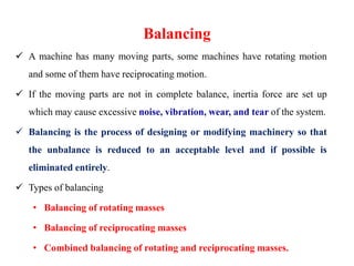
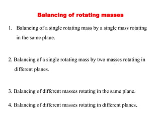
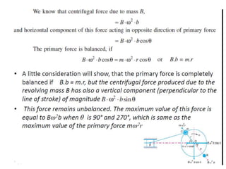
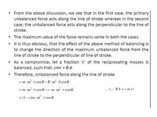
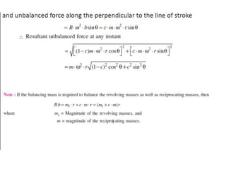
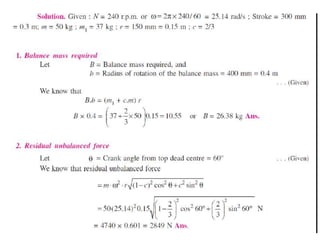
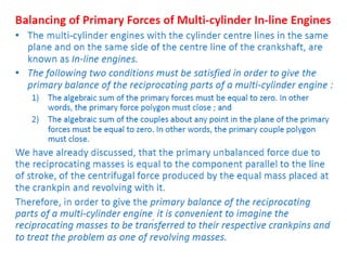
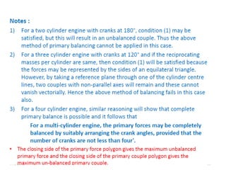
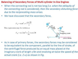
1. The document discusses balancing of rotating and reciprocating machine parts to reduce vibration. Balancing involves analyzing unbalanced forces and designing or modifying parts to eliminate unbalance.
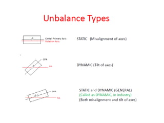
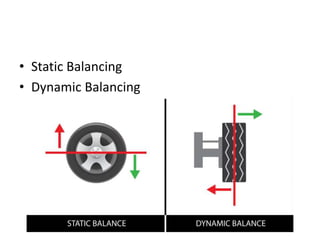
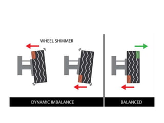
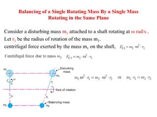
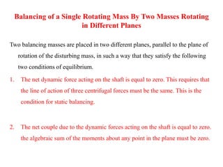
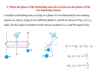
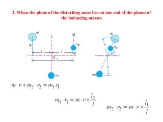
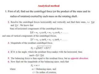
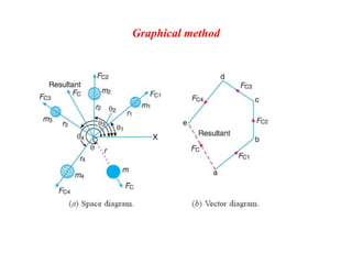
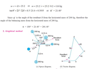
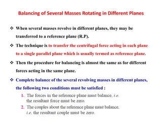
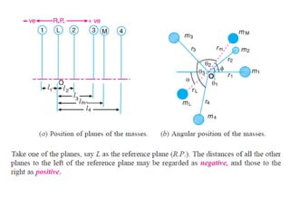
2. There are different methods of balancing depending on whether parts rotate or reciprocate, and whether in the same or different planes. Analytical and graphical methods are provided to calculate balancing masses or positions.
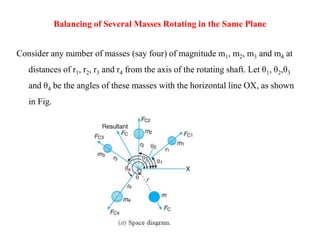
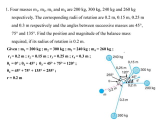
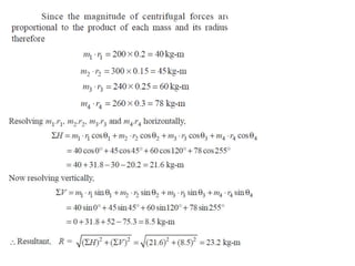
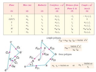
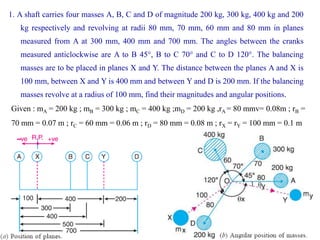
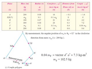
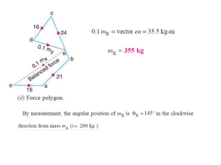
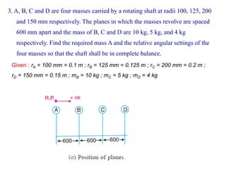
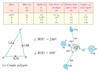
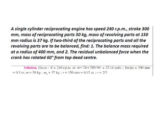
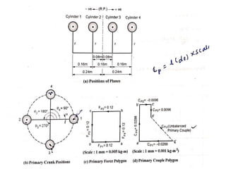
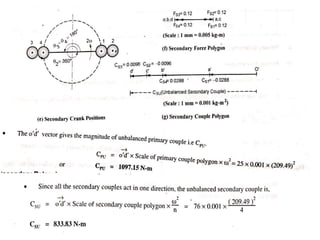
3. Several examples are given to demonstrate balancing of multiple rotating masses in the same or different planes using given mass properties and geometry to calculate required balancing masses or positions.