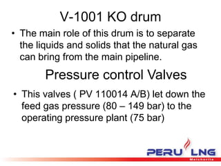
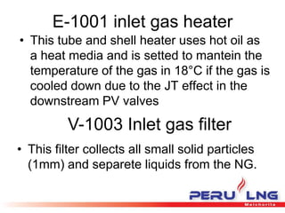
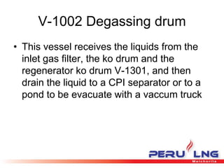
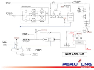
Unit 1000
Inlet Gas Area
By Cesar Gastiaburu
Process Overview
• The inlet gas area is the first step process
in the LNG plant which receives the NG
from Camisea. The principal role of this
area is to meter the NG consumption ,
reduce the feed gas pressure and
separate liquids and solids that can have
the NG
Principal components
• Metering system
• HIPPS valves ESDV 110011 A/B
• V-1001 KO drum
• Pressure control Valves PV-110014 A/B
• E-1001 Inlet gas heater
• V-1003 Inlet gas filter
• V-1002 Degassing drum
Metering System
• The metering system consist in three
ultrasonic flow meters runs and in normal
operation there will be two online meters
and one in standby.
• Chromatograph gas analizer which have
readings of C1,C2, C3, C4, C5, etc
• Benzene analizer
• Gas specific gravity analyser
HIPPS valves
• The purpose of this valves is to protect the
downstream part of the plant of
overpressure, using three pressure
transmiters with the logic two out of three,
it means if two transmiters have an
overpressure reading the plant will trip
V-1001 KO drum
• The main role of this drum is to separate
the liquids and solids that the natural gas
can bring from the main pipeline.
Pressure control Valves
• This valves ( PV 110014 A/B) let down the
feed gas pressure (80 – 149 bar) to the
operating pressure plant (75 bar)
E-1001 inlet gas heater
• This tube and shell heater uses hot oil as
a heat media and is setted to mantein the
temperature of the gas in 18°C if the gas is
cooled down due to the JT effect in the
downstream PV valves
V-1003 Inlet gas filter
• This filter collects all small solid particles
(1mm) and separete liquids from the NG.
V-1002 Degassing drum
• This vessel receives the liquids from the
inlet gas filter, the ko drum and the
regenerator ko drum V-1301, and then
drain the liquid to a CPI separator or to a
pond to be evacuate with a vaccum truck
Unit 1000 gas inlet

Unit 1000 gas inlet

  • 1.
    Unit 1000 Inlet GasArea By Cesar Gastiaburu
  • 2.
    Process Overview • Theinlet gas area is the first step process in the LNG plant which receives the NG from Camisea. The principal role of this area is to meter the NG consumption , reduce the feed gas pressure and separate liquids and solids that can have the NG
  • 3.
    Principal components • Meteringsystem • HIPPS valves ESDV 110011 A/B • V-1001 KO drum • Pressure control Valves PV-110014 A/B • E-1001 Inlet gas heater • V-1003 Inlet gas filter • V-1002 Degassing drum
  • 4.
    Metering System • Themetering system consist in three ultrasonic flow meters runs and in normal operation there will be two online meters and one in standby. • Chromatograph gas analizer which have readings of C1,C2, C3, C4, C5, etc • Benzene analizer • Gas specific gravity analyser
  • 5.
    HIPPS valves • Thepurpose of this valves is to protect the downstream part of the plant of overpressure, using three pressure transmiters with the logic two out of three, it means if two transmiters have an overpressure reading the plant will trip
  • 6.
    V-1001 KO drum •The main role of this drum is to separate the liquids and solids that the natural gas can bring from the main pipeline. Pressure control Valves • This valves ( PV 110014 A/B) let down the feed gas pressure (80 – 149 bar) to the operating pressure plant (75 bar)
  • 7.
    E-1001 inlet gasheater • This tube and shell heater uses hot oil as a heat media and is setted to mantein the temperature of the gas in 18°C if the gas is cooled down due to the JT effect in the downstream PV valves V-1003 Inlet gas filter • This filter collects all small solid particles (1mm) and separete liquids from the NG.
  • 8.
    V-1002 Degassing drum •This vessel receives the liquids from the inlet gas filter, the ko drum and the regenerator ko drum V-1301, and then drain the liquid to a CPI separator or to a pond to be evacuate with a vaccum truck