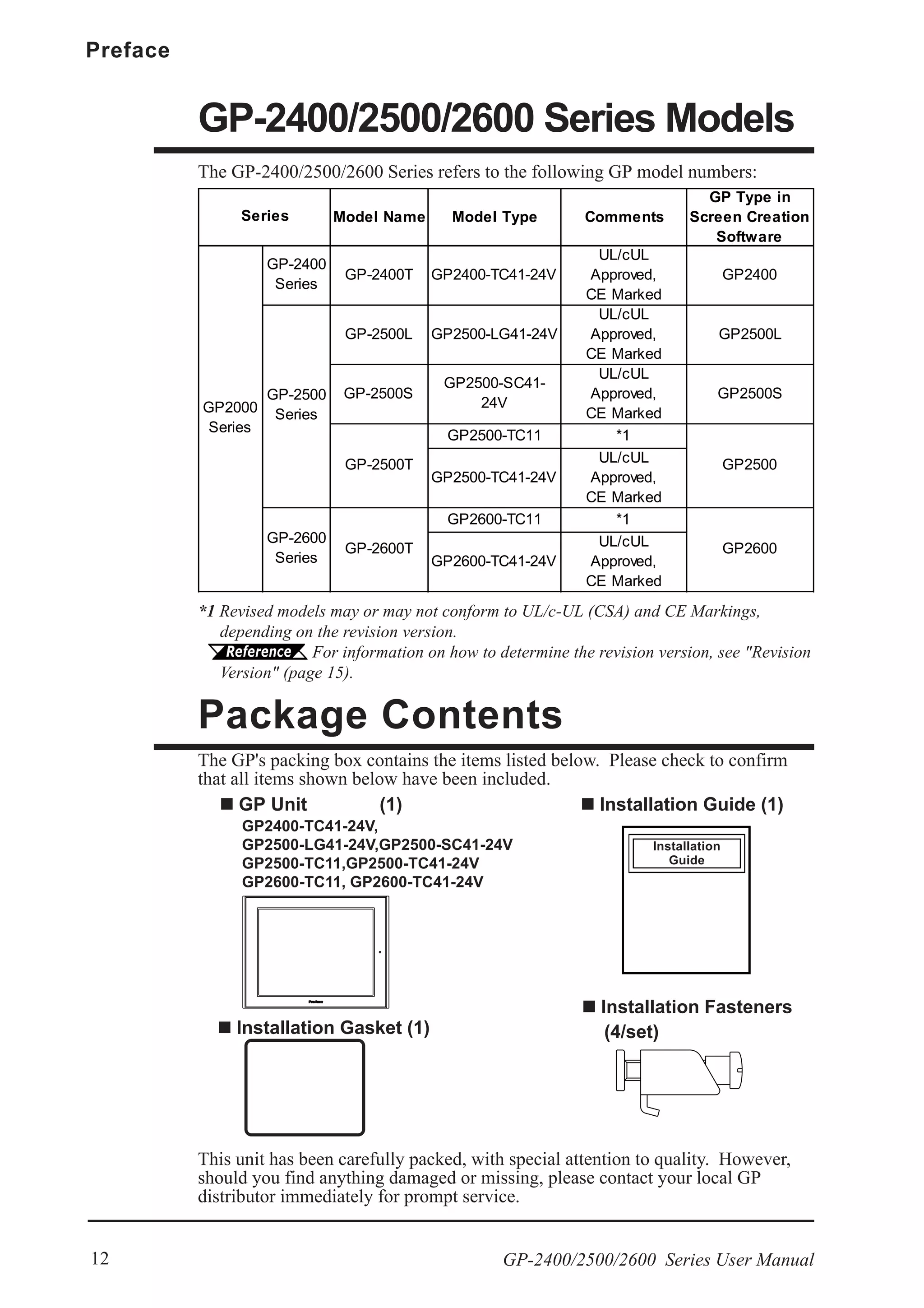
The document is the user manual for the Pro-face GP-2400/2500/2600 series programmable operator interface, detailing its features, safety precautions, and operational instructions. It includes sections on installation, specifications, data transfer, troubleshooting, and maintenance procedures. Users are advised to read the manual thoroughly to ensure correct and safe usage of the GP unit.


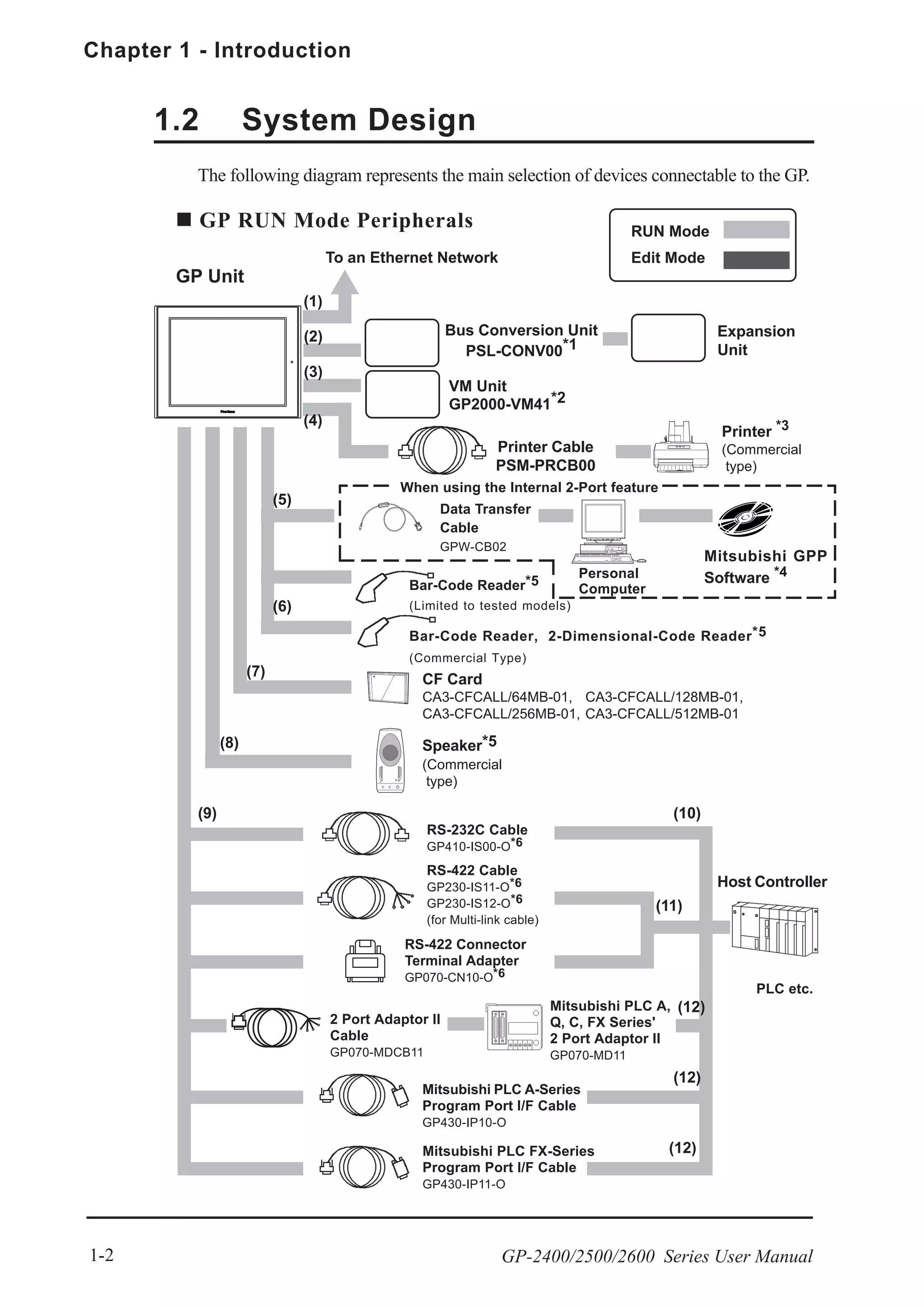

![Chapter 1 - Introduction
GP-2400/2500/2600 Series User Manual1-12
1.4.2 CF Card
The new GP-2400/2500/2600 series unit allows you to use a CF Card without
installing the separately sold Multi Unit. You can set up the GP or send screen data
by saving backup data (i.e. all necessary data for GP operation) in the CF Card
using the GP’s CF Memory Loader Tool feature. As with the Multi Unit, all the
following features are available with a GP-2400/2500/2600 series unit.
• Read filing data from CF Card
• Write logging data to CF Card
• Read image data or sound data from CF Card
• Write Graph data or Alarm data to CF Card
• Back up screen data to CF Card
For details about creating / saving backup data (i.e. all necessary data for GP operation)
and sending GP data, refer to
GP-PRO/PBIII for Windows Operation Manual
For details about CF Memory Loader Tool’s data upload and download, refer to
4.3 Memory Loader Tool
When using the "CF Memory Loader Tool", Digital's GP077-CF20 (16MB)
or GP077-CF30 (32MB) Memory Card is required.
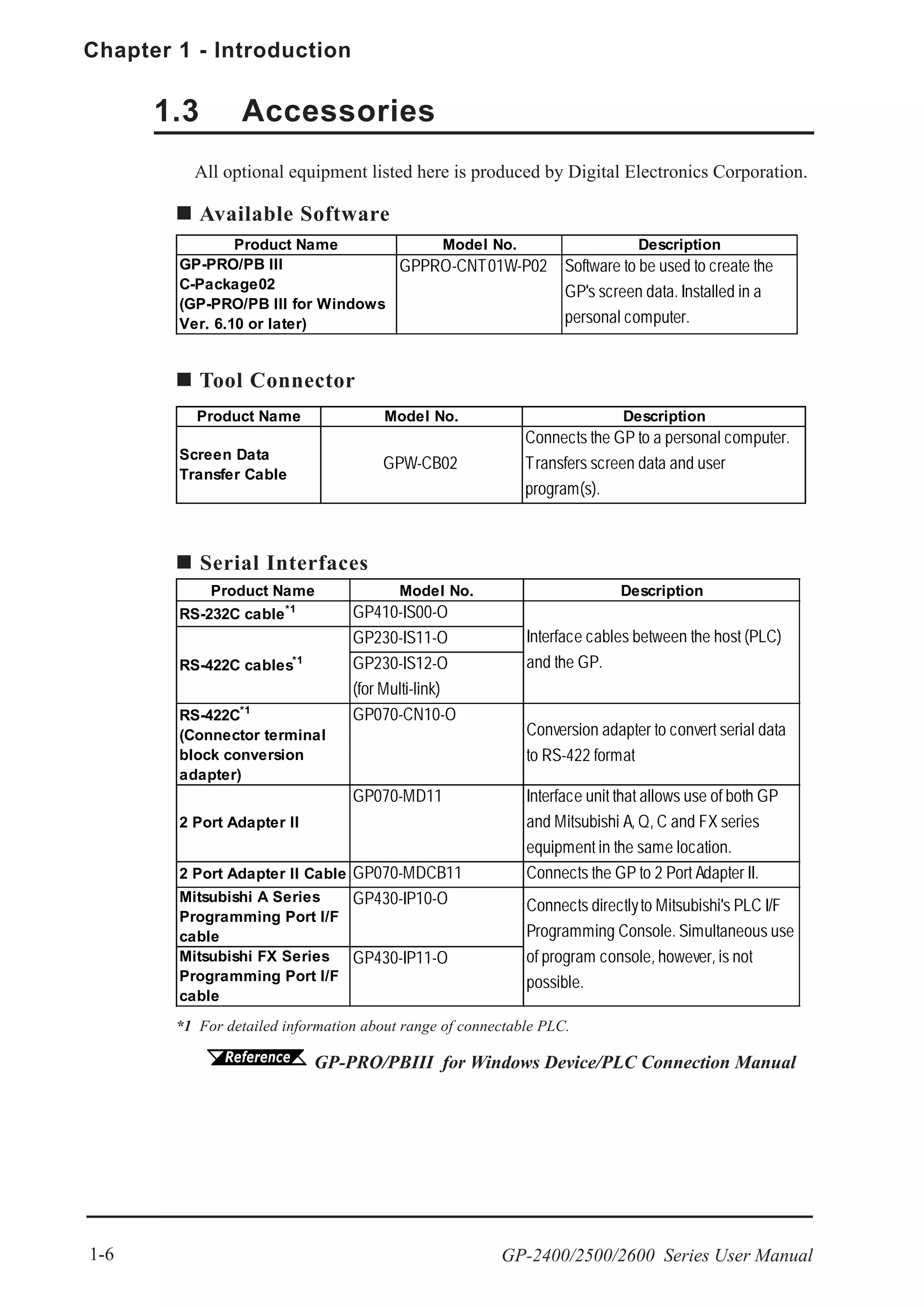
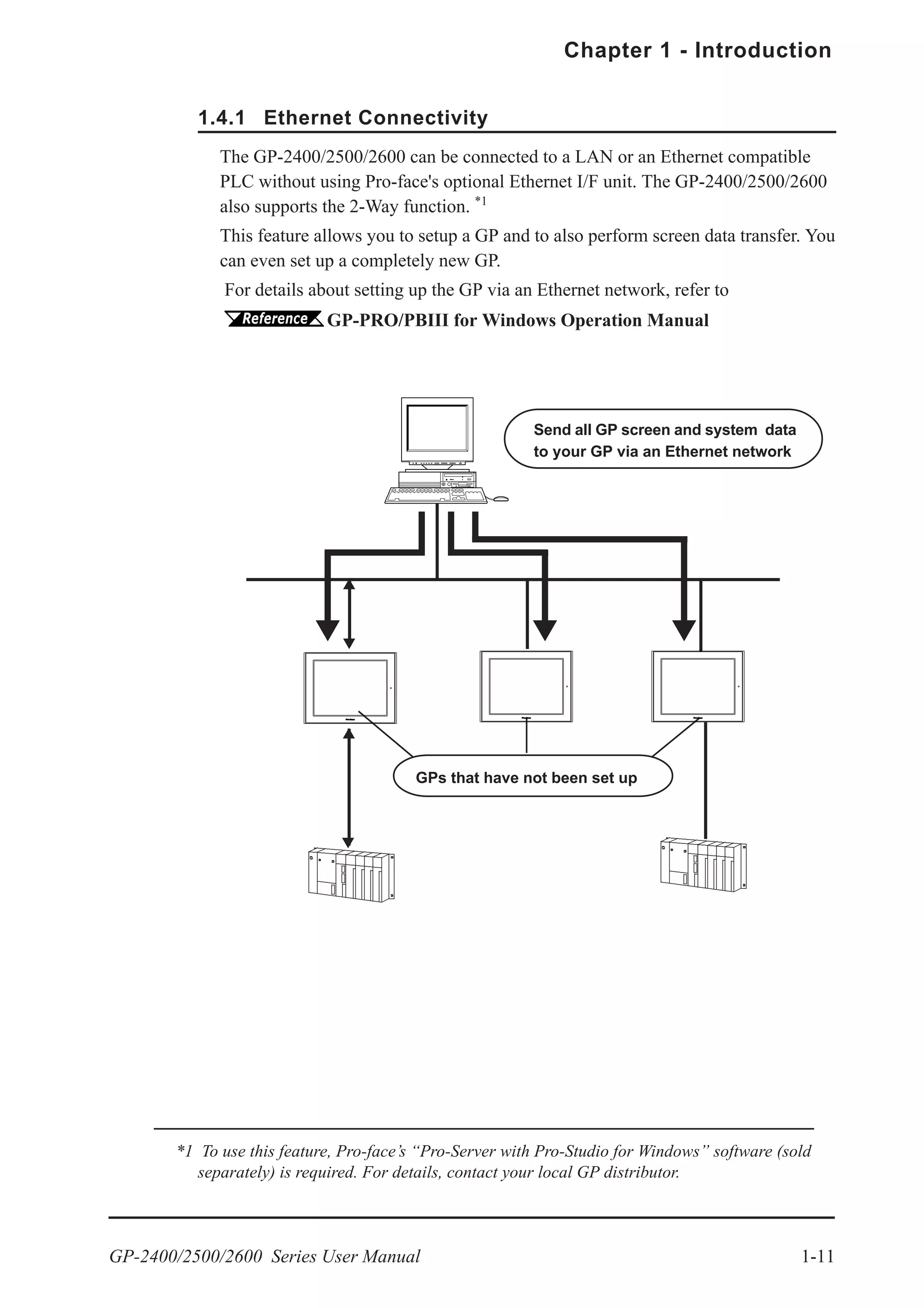
Send GP Screen Data to a CF card, then to other GPs
The CF Card allows you to set up multiple GPs, using a single GP's data.
Copy your GP data and the "CF Memory Loader Tool" to your GP’s CF Card,
then insert that CF Card in another GP and transfer that data using the the CF
Memory Loader Tool.
Send GP Screen Data to a GP, then to the CF card
You can also use the GP as a CF Card drive for your PC, by sending data from
your PC directly to your GP's CF Card, . Simply connect your PC and the GP
using the data transfer cable, and send your backup data and the CF Memory
Loader Tool to the CF Card installed in the GP.
Copy data using
GP-PRO/PBIII’s
[CF Card Tool]
Transfer data to
G P v i a " C F
Memory Loader
Tool"
Send data using
GP-PRO/PBIII’s
[Transfer] feature
At a transmission speed of 115.2kbps, it takes approximately fifteen minutes to
transfer screen and system data to a GP.](https://image.slidesharecdn.com/gp2400-2500-2600manual-150602072814-lva1-app6891/75/Proface-GP2400-GP2500-GP2501-GP2600-manual-29-2048.jpg)

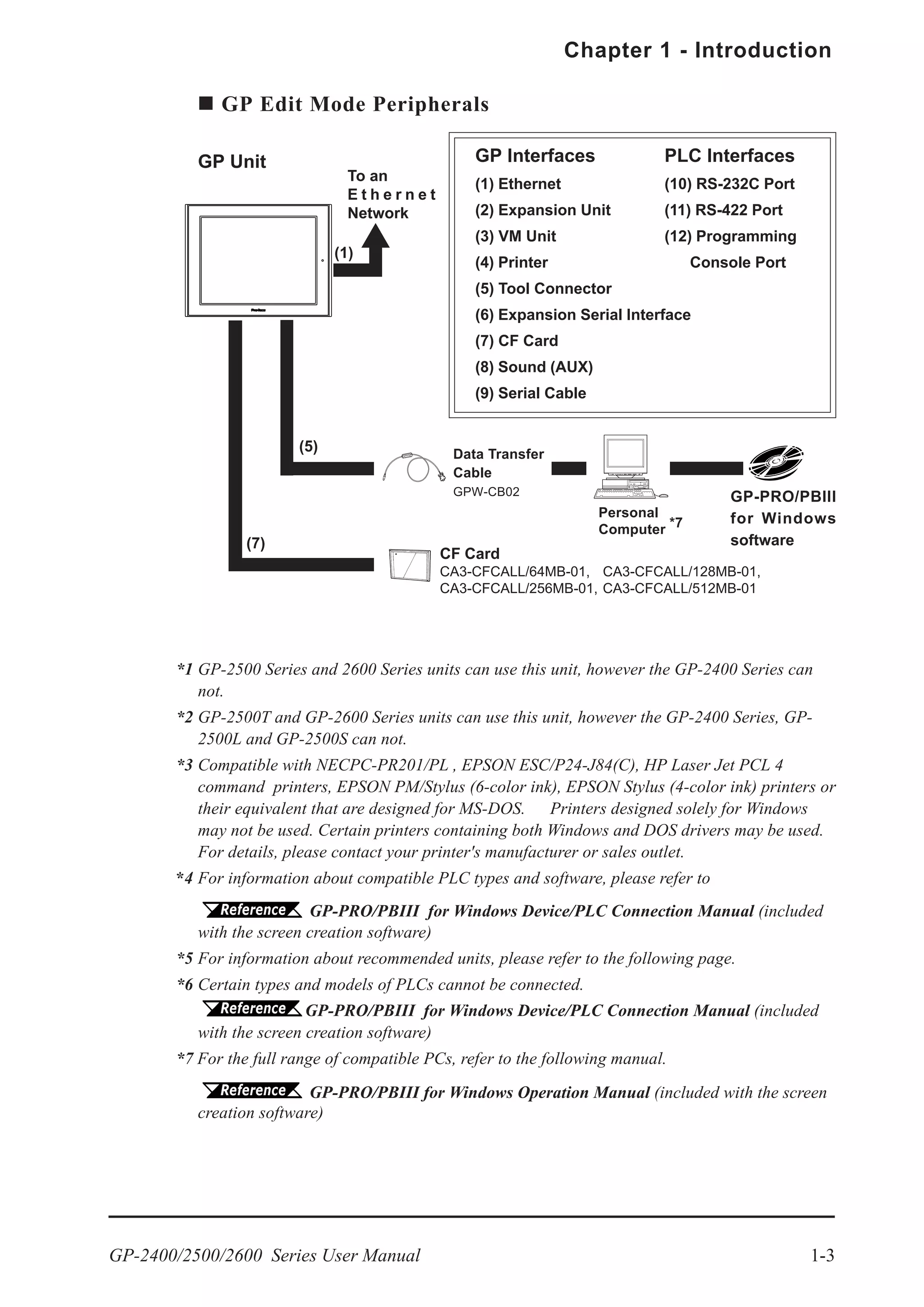
![GP-2400/2500/2600 Series User Manual 1-15
Chapter 1 - Introduction
Internal 2-Port Feature Usage Notes
• To use the Internal 2-Port feature, you will need to adjust your GP’s settings.
For information about these settings, refer to
GP-PRO/PBIII for Windows Device/PLC Connection Manual
(included with the GP Screen creation software)
• This feature can be used only while the GP is in ONLINE mode.
• Since the internal 2-Port feature uses the GP’s single tool connector, you will
not be able to use equipment which requires the tool connector (i.e. a Barcode
Reader, Optional Items, etc.)
• If you transfer screen data while the GP is in ONLINE mode, the screen will
not change to the data transfer screen automatically. Thus, you will need to
change the screen manually to the OFFLINE mode's [Main Menu/ Transfer]
screen.
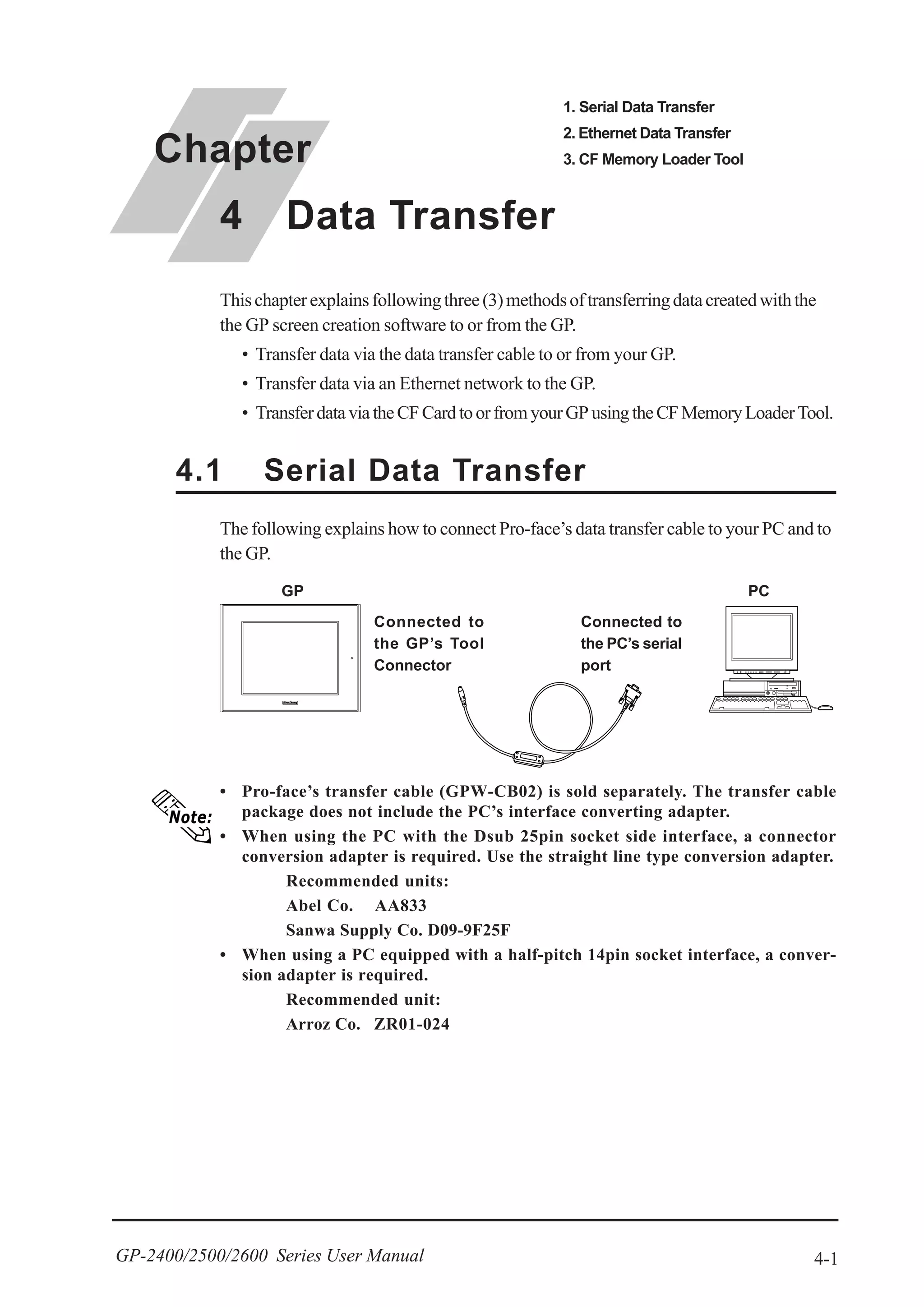
4.1 Serial Data Transfer
• Peripheral equipment, such as a Programming Console, is not compatible with
the GP's Internal 2-Port feature. To use this type of equipment, you will need to
use the external 2- Port Adapter II.
1.4.6 Backlight Burnout Detection Feature
When the GP’s backlight burns out, it will be automatically detected. The GP’s
Status LED will alert you that the backlight is burned out so that you can disable
GP Touch Panel Operation and prevent a possible GP operation mistake. When
Backlight Burnout is detected the GP's Status LED will turn orange. Also, the
system data area’s “Status” bit10 *1
will turn ON.
For details about touch panel operation when the backlight burned
out, refer to 6.4.3 SET UP TOUCH PANEL.
*1 When using the Direct Access method, bit +6 will turn ON. The using Memory Link
method, bit 11 will turn ON. For details, refer to GP-PRO/PBIII for
Windows Device/PLC Connection Manual (included with the GP screen creation software)](https://image.slidesharecdn.com/gp2400-2500-2600manual-150602072814-lva1-app6891/75/Proface-GP2400-GP2500-GP2501-GP2600-manual-32-2048.jpg)


![GP-2400/2500/2600 Series User Manual 2-3
Chapter 2 - Specifications
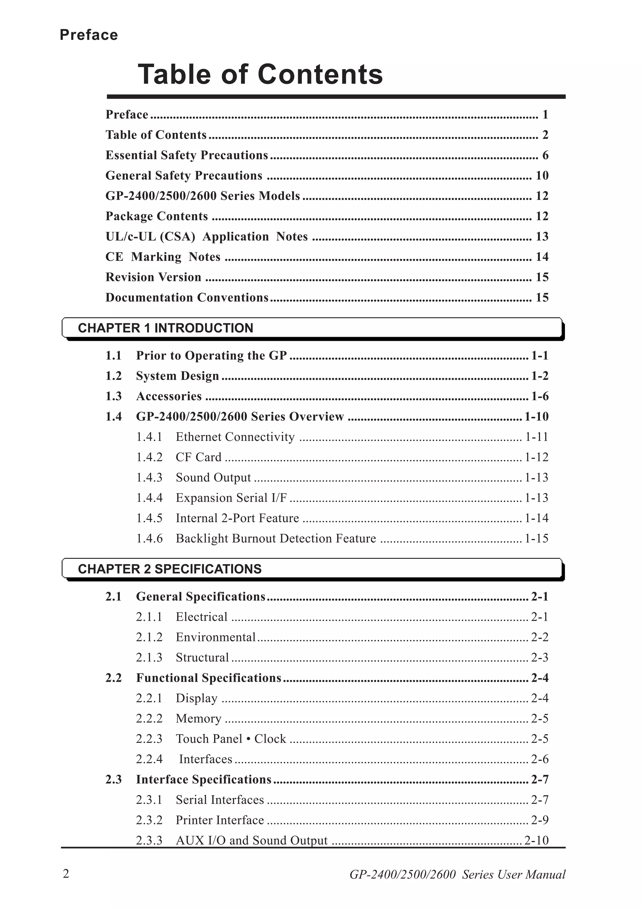
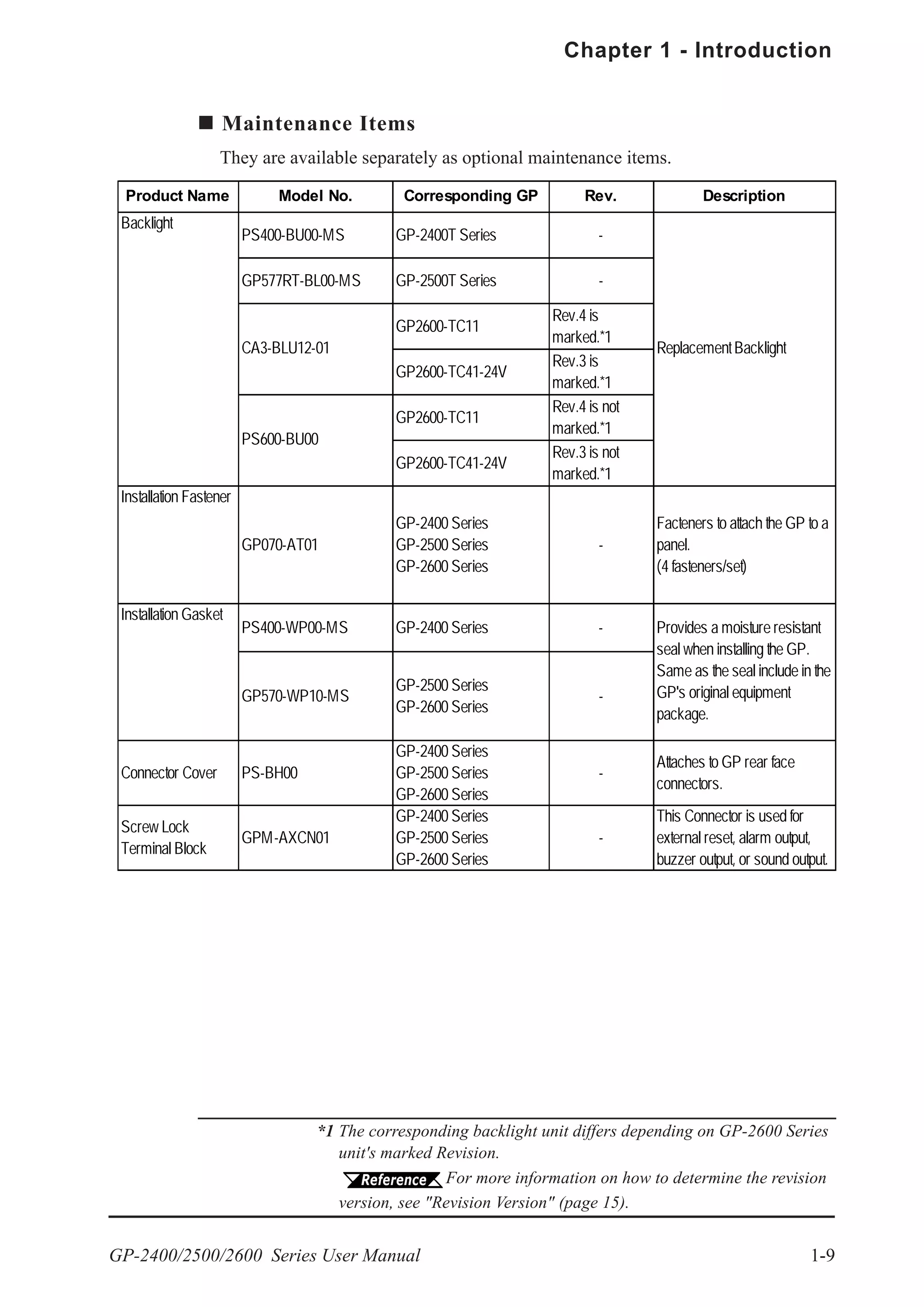
2.1.3 Structural
GP-2400 Series GP-2500 Series GP-2600 Series
Grounding
Ratings
*1
(For front panel of installed unit)
Weight 1.7 kg (5.5lb) or less
Cooling Method
External Dimensions
W215mm [8.46in] x
H170mm [6.69in]
x D60mm [2.36in]
W317mm [12.48in] x H243mm [9.57in]
x D58mm [2.28in]
100Ω or less, or your country's applicable standard
3.5kg (7.7lb) or less
Natural air circulation
Equivalent to IP65f (JEM 1030)
NEMA#250 Type4X/12
*1 The front face of the GP unit, installed in a solid panel, has been tested using
conditions equivalent to the standards shown in the specification. Even though
the GP unit’s level of resistance is equivalent to these standards, oils that should
have no effect on the GP can possibly harm the unit. This can occur in areas
where either vaporized oils are present, or where low viscosity cutting oils are
allowed to adhere to the unit for long periods of time. If the GP’s front face
protection sheet becomes peeled off, these conditions can lead to the ingress of
oil into the GP and separate protection measures are suggested. Also, if non-
approved oils are present, it may cause deformation or corrosion of the front
panel’s plastic cover. Therefore, prior to installing the GP be sure to confirm the
type of conditions that will be present in the GP’s operating environment. If the
installation gasket is used for a long period of time, or if the unit and its gasket
are removed from the panel, the original level of the protection cannot be guar-
anteed. To maintain the original protection level, you need to replace the instal-
lation gasket regularly.](https://image.slidesharecdn.com/gp2400-2500-2600manual-150602072814-lva1-app6891/75/Proface-GP2400-GP2500-GP2501-GP2600-manual-36-2048.jpg)
![Chapter 2 - Specifications
GP-2400/2500/2600 Series User Manual2-4
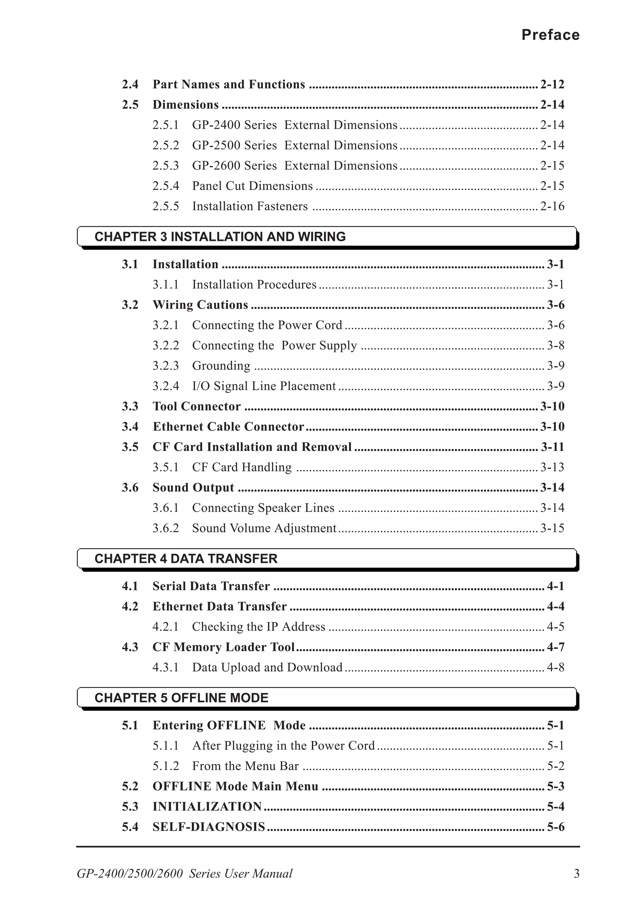
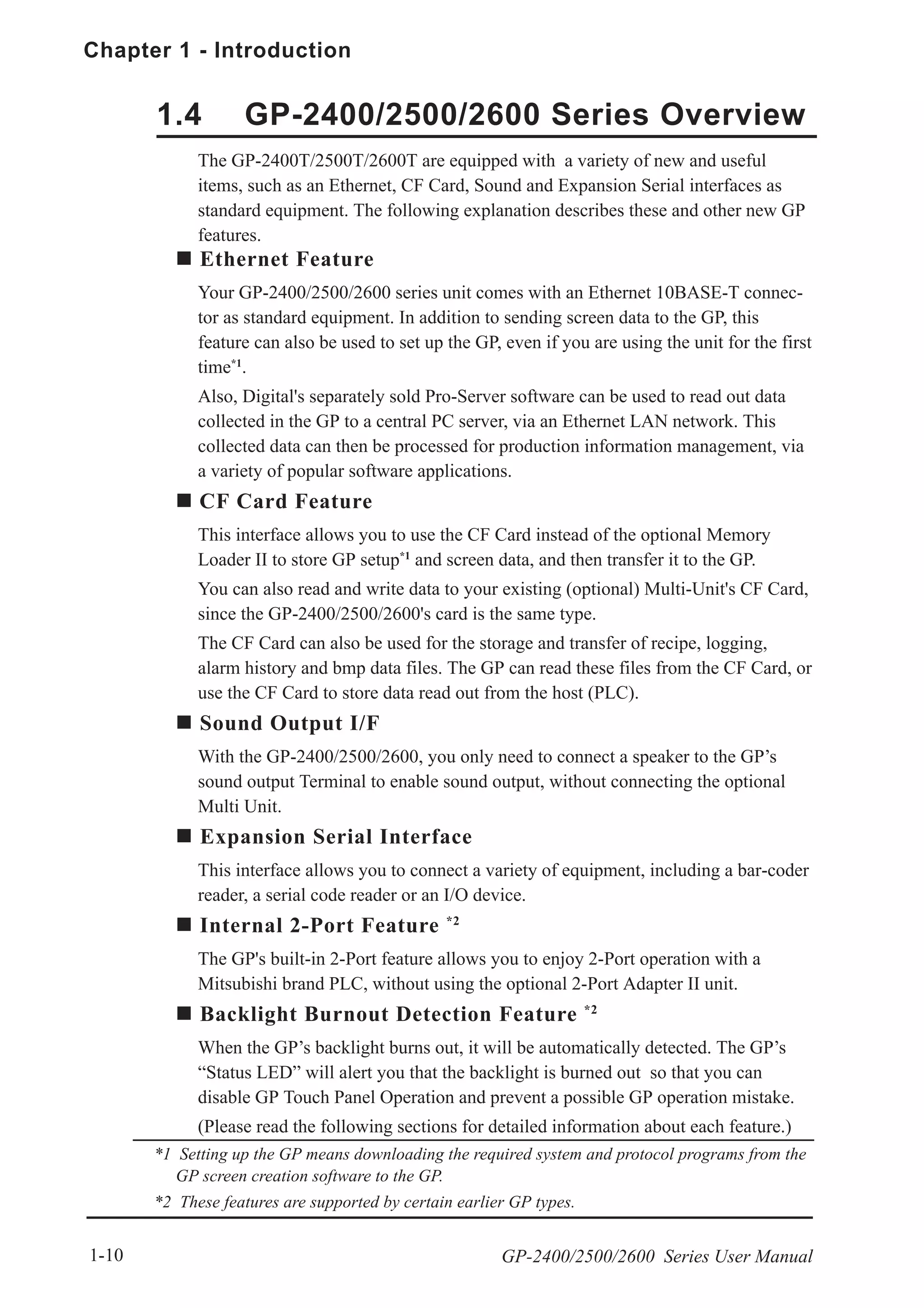
2.2 Functional Specifications
2.2.1 Display
GP-2400 Series GP-2500 Series GP-2600 Series
GP-2500L
Monochrome LCD
GP-2500S
STN type color LCD
GP-2500T
TFT type color LCD
GP-2500L
Black and White,
2 levels of gray/
Black and White,
8 levels of gray*3
(Color switching is done
via software)
GP-2500S
64 colors / 3-speed blink
GP-2500T
256 / No blink*1
,
64 colors / 3-speed blink
(Color switching is done
via software)
Resolution 800 x 600pixels
W149.8mm [5.90in.] x
H112.3mm [4.42in.]
W211.2mm [8.34in.] x
H158.4mm [6.24in.]
W246mm [9.69in.] x
H184.5mm [7.26in.]
8x8 dots 100 Char. x 75 rows
8x16 dots 100 Char. x 37 rows
16x16 dots 50 Char. x 37 rows
32x32 dots 25 Char. x 18 rows
Backlight
8 levels of adjustment
available via touch panel.
(GP-2500L/S Only)
Contrast
Adjustment
TFT type color LCD
Colors
256 / No blink*1
,
64 colors / 3-speed blink
(Color switching is done
via software)
256 / No blink*1
,
64 colors / 3-speed blink
(Color switching is done
via software)
Effective Display
Area
Language Fonts
ASCII: (Code page 850) Alphanumeric (incl. Eur. characters)
Chinese: (GB2312-80 codes) simplified Chinese fonts
Japanese: ANK 158, Kanji : 6962 (JIS Standards 1 & 2)
Korean: (KSC5601 - 1992 codes) Hangul fonts
Taiwanese: (Big 5 codes) traditional Chinese fonts
Text
80 Char. x 60 rows
640 x 480pixels
Type TFT type color LCD
80 Char. x 30 rows
40 Char. x 30 rows
20 Char. x 15 rows
Font Sizes
Hight can be expanded 1 to 8 times.
Width can be expanded 1/2*4
, 1 to 8 times.
CCFL (Service life: 50,000 hrs. at 25o
C and 24hr. operation)
Brightness Control 4 levels of adjustment available via touch panel.
Character Sizes *2 8X8 dot font, 8X16 dot font, 16X16 dot font and 32X32 dot font](https://image.slidesharecdn.com/gp2400-2500-2600manual-150602072814-lva1-app6891/75/Proface-GP2400-GP2500-GP2501-GP2600-manual-37-2048.jpg)
![Chapter 2 - Specifications
GP-2400/2500/2600 Series User Manual2-10
This interface is used for external reset, alarm output, buzzer output, or sound output.
2.3.3 AUX I/O and Sound Output
Pin Assingments Pin # Signal Name Condition
1 AUXCOM External Reset Common
2 AUXRESET External Reset Input
3 RUN ONLINE Operation
4 ALARM System Alarm Output
5 OUTCP DC24V
6 BUZZ External Buzzer Output
7 RESERVE Reserved
8 OUTCN 0V
9 RESERVE Reserved
10 SP OUT Speaker Output
11 GND Ground
12 LINE OUT Sound Lineout Output
1
12
Input Circuit
560Ω
InternalCircuit
Input Section
5.4kΩ
DC24V
AUXRESET
Input Voltage DC24V +/- 10%
InputCurrent 4mA/DC24V(TYP)
Min. Input Pulse Width 2ms
Operating Voltage ONVoltagemin. DC21.2V
OFF Voltage max. DC 3V
TerminationType Photo-CouplerIsolation
AUXCOM
Torque: 0.2 to 0.4N•m
Wire Gauge: AWG16 to AWG 28
Removed Wire Length: 7 +/- 0.5mm [0.28 +/- 0.02 in.]](https://image.slidesharecdn.com/gp2400-2500-2600manual-150602072814-lva1-app6891/75/Proface-GP2400-GP2500-GP2501-GP2600-manual-43-2048.jpg)

![Chapter 2 - Specifications
GP-2400/2500/2600 Series User Manual2-14
Unit: mm [in.]
2.5 Dimensions
2.5.2 GP-2500 Series External Dimensions
Top
Front Side
301 [11.85]
58 [2.28]
227[8.94]
8 [0.31]
243[9.57]
317 [12.48]
Unit: mm [in.]
2.5.1 GP-2400 Series External Dimensions
Top
Front
Side
204 [8.03]
60 [2.36]
159[6.26]
8 [0.31]
170[6.69]
215 [8.46]](https://image.slidesharecdn.com/gp2400-2500-2600manual-150602072814-lva1-app6891/75/Proface-GP2400-GP2500-GP2501-GP2600-manual-47-2048.jpg)
![GP-2400/2500/2600 Series User Manual 2-15
Chapter 2 - Specifications
2.5.3 GP-2600 Series External Dimensions
Unit: mm [in.]
Top
Front Side
301 [11.85]
58 [2.28]
227[8.94]
8 [0.31]
243[9.57]
317 [12.48]
2.5.4 Panel Cut Dimensions
Unit: mm [in.]
4-R3[0.12] or less
4-R3[0.12] or less
204.5
+1
0
159.5
+1
0[6.28]
+0.04
0
[8.05 ]
+0.04
0
GP-2400 Series
Unit: mm [in.]
GP-2500/2600 Series
[8.96]
227.5
+1
0
+0.04
0
301.5
+1
0 [11.87 ]
+0.04
0](https://image.slidesharecdn.com/gp2400-2500-2600manual-150602072814-lva1-app6891/75/Proface-GP2400-GP2500-GP2501-GP2600-manual-48-2048.jpg)
![Chapter 2 - Specifications
GP-2400/2500/2600 Series User Manual2-16
2.5.5 Installation Fasteners
Unit: mm [in.]
16[0.63]
31[1.22]
19.5[0.77]
10[0.39]
11[0.43]](https://image.slidesharecdn.com/gp2400-2500-2600manual-150602072814-lva1-app6891/75/Proface-GP2400-GP2500-GP2501-GP2600-manual-49-2048.jpg)
![Chapter 3 - Installation and Wiring
3-2 GP-2400/2500/2600 Series User Manual
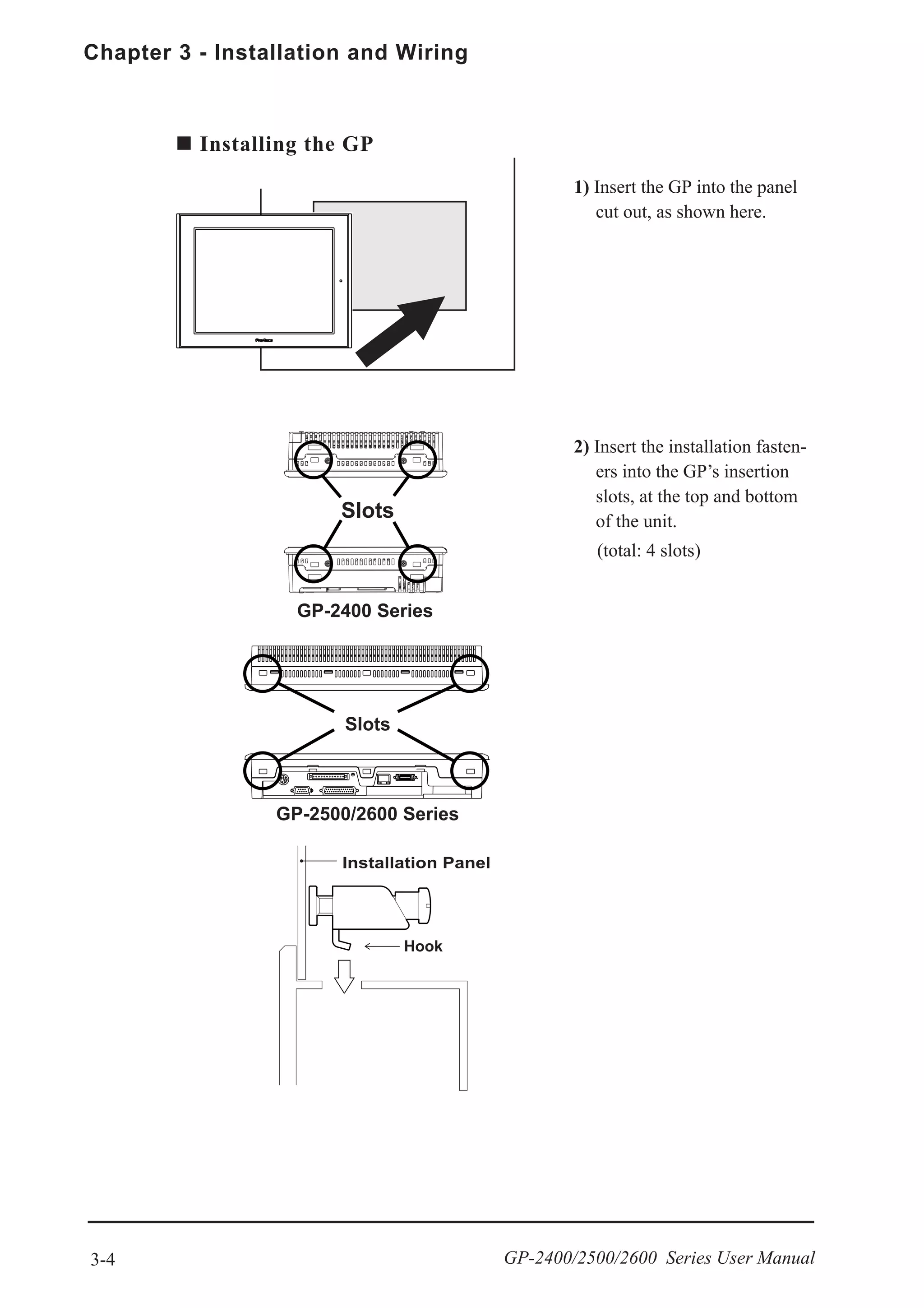
Creating a Panel Cut
Create the correct sized opening required to install the GP, using the installation
dimensions given.
2.5.4 GP Panel Cut Dimensions
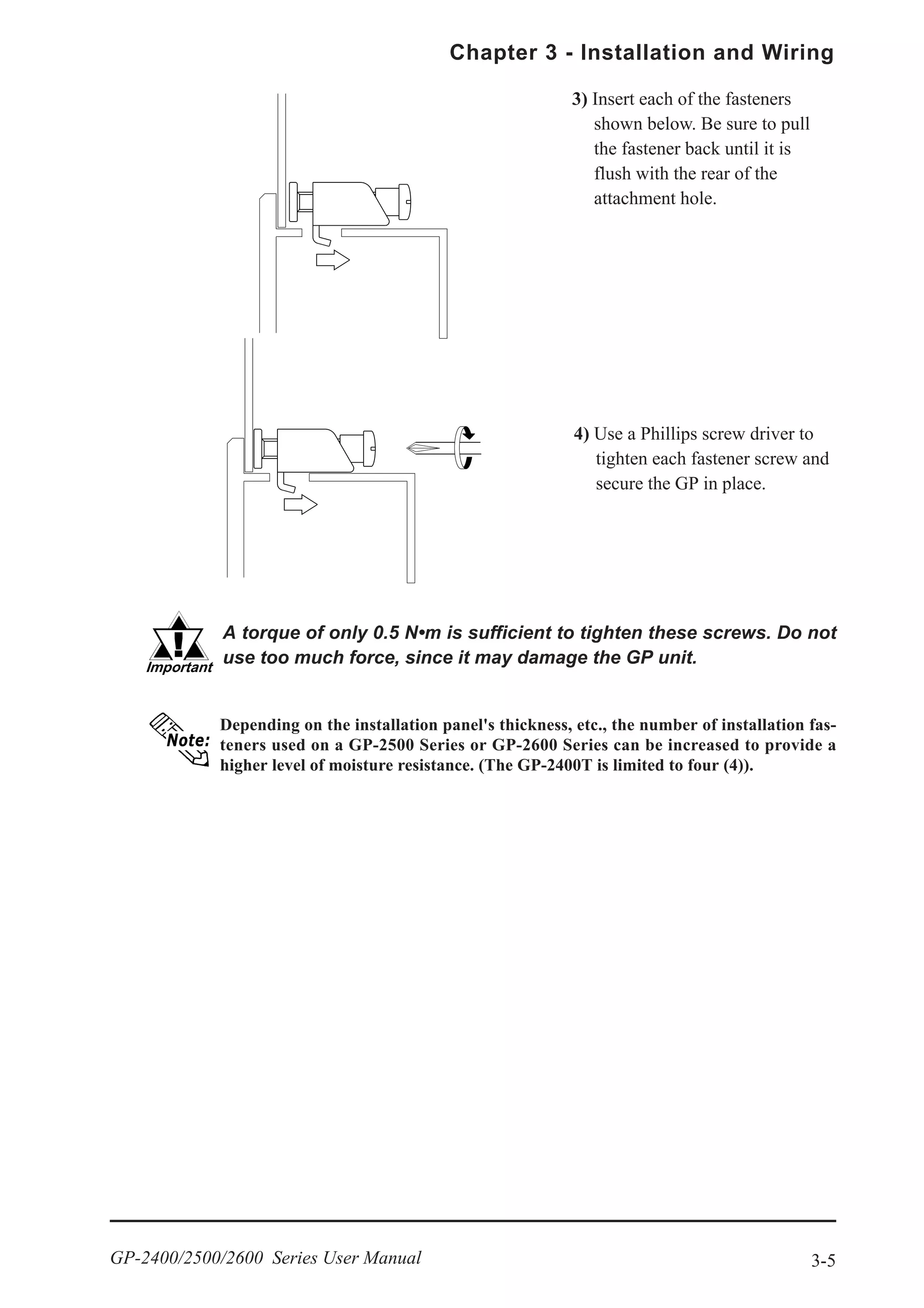
The installation gasket, installation brackets and attachment screws are all re-
quired when installing the GP.
Check that the installation panel or cabinet's surface is flat, in good condition and has
no jagged edges. Also, if desired, metal reinforcing strips can be attached to the inside
of the panel, near the Panel Cut, to increase the panel’s strength.
For easier maintenance, operation, and improved ventilation, be sure
to install the GP at least 100 mm [3.94 in.] away from adjacent struc-
tures and other equipment.
Panel thickness should be from 1.6mm [0.06in.] to 10mm [0.4in.]. De-
cide the panel’s thickness based on the level of panel strength required.
Panel Cut
Area
Panel](https://image.slidesharecdn.com/gp2400-2500-2600manual-150602072814-lva1-app6891/75/Proface-GP2400-GP2500-GP2501-GP2600-manual-51-2048.jpg)
![3-9
Chapter 3 - Installation and Wiring
GP-2400/2500/2600 Series User Manual
3.2.3 Grounding
(a) Exclusive Grounding (BEST) *1 Connect the FG terminal found at the back
of the GP to an exclusive ground. [dia-
gram (a)].
(b) Common Grounding (OK)*1
• Check that the grounding re-
sistance is less than 100ΩΩΩΩΩ.
• The SG and FG terminals are
connected internally in the
GP unit.
• When connecting the SG line
to another device, be sure
that the design of the system/
connection does not produce
a shorting loop.
• The grounding wire should
have a cross sectional area
greater than 2mm2
. Create
the connection point as close
to the GP unit as possible,
and make the wire as short,
as possible. When using a
long grounding wire, replace
the thin wire with a thicker
wire, and place it in a duct.
(c) Common Grounding (Not OK)
Input and output signal lines must be separated from the power control cables
for operating circuits.
If this is not possible, use a shielded cable and connect the shield to the GP's
frame.
3.2.4 I/O Signal Line Placement
If exclusive grounding is not possible, use a
common connection point. [diagram (b)]
If the equipment does not function
properly when grounded, disconnect
the ground wire from the FG termi-
nal.
*1 Use a grounding resistance of less than 100Ω and a 2mm2
or greater thickness wire,
or your country’s applicable standard. For details, contact your local GP distributor.
Do not use common grounding, since it can lead to an acci-
dent or machine breakdown.
CAUTION](https://image.slidesharecdn.com/gp2400-2500-2600manual-150602072814-lva1-app6891/75/Proface-GP2400-GP2500-GP2501-GP2600-manual-58-2048.jpg)
![Chapter 3 - Installation and Wiring
3-14 GP-2400/2500/2600 Series User Manual
3.6 Sound Output
3.6.1 Connecting Speaker Lines
Use the following steps to connect the speaker.
(The illustrations below show the procedures for the GP-2500/2600 Series mod-
els. However, these procedures are also the same for the GP-2400 Series.)
4) Confirm that each line (cable) is
inserted completely, and retighten the
two (2) set screws.
Torque: 0.2 to 0.4 N•m
1) Rotate the screw lock terminal block’s
two (2) levers in the direction shown
(downward), and remove the screw
lock terminal block.
2) Unscrew #11 pin and #10 pin set
screws (2nd and 3rd screws from the
left).
3) Insert the Speaker’s GND line in #11
pin connector, and the SP OUT line in
#10 pin connector.
Wire Gauge:AWG 16 to AWG 28
Removed Wire Length: 7 +/- 0.5mm
[0.28 +/-0.02 in.]](https://image.slidesharecdn.com/gp2400-2500-2600manual-150602072814-lva1-app6891/75/Proface-GP2400-GP2500-GP2501-GP2600-manual-63-2048.jpg)


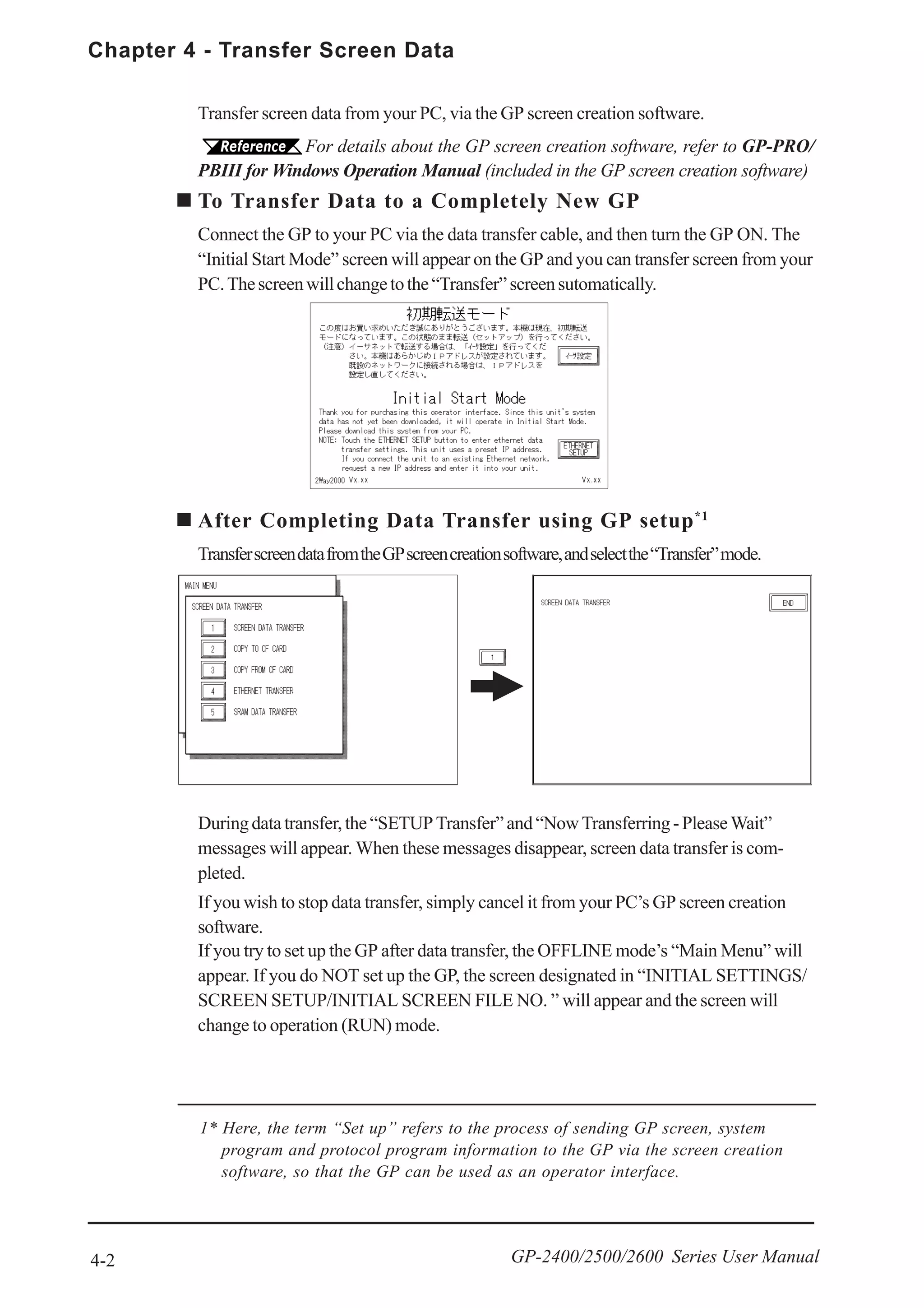
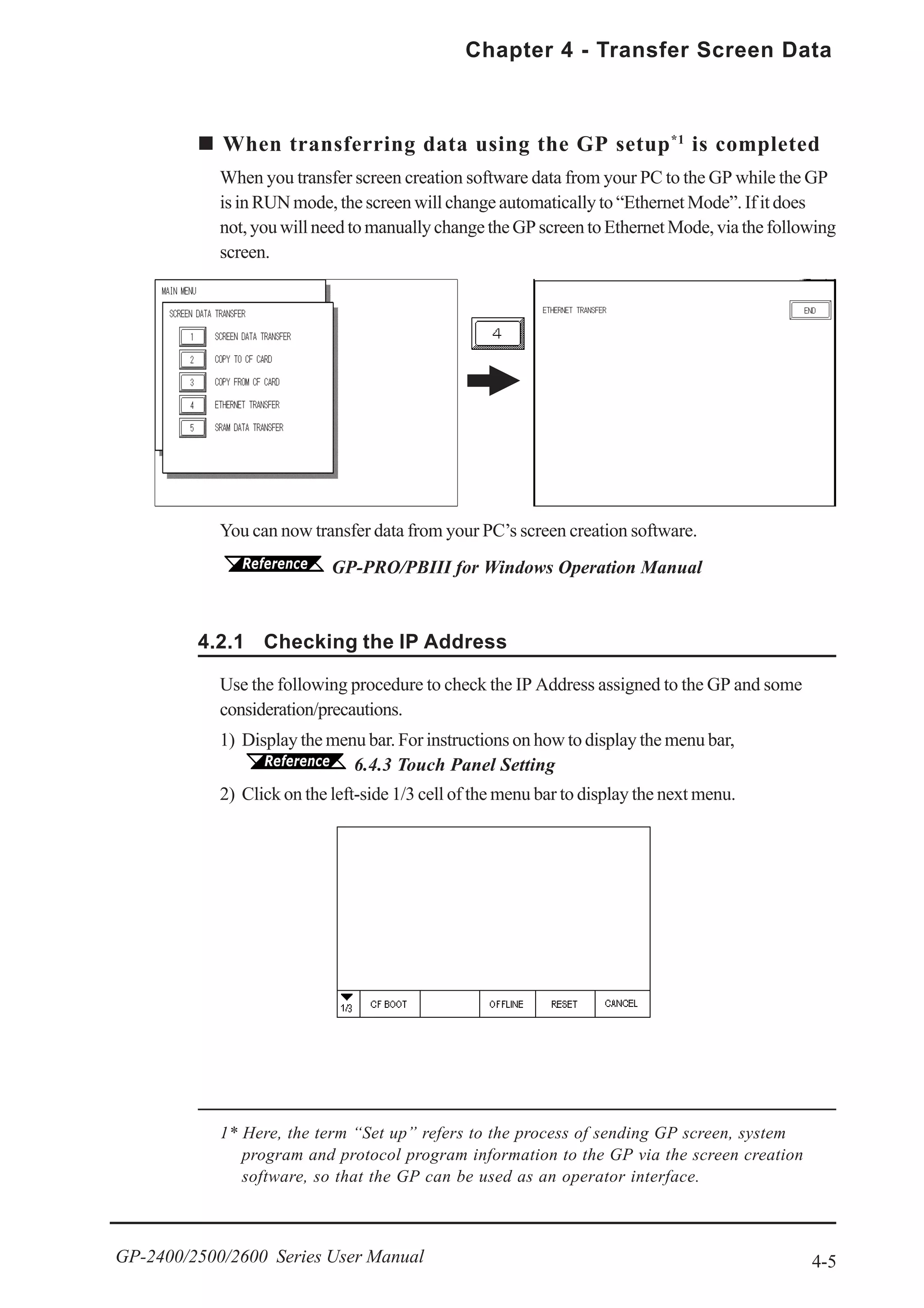
![Chapter 4 - Transfer Screen Data
4-4 GP-2400/2500/2600 Series User Manual
The GP-2400/2500/2600 is equipped with the Ethernet I/F which allows you to set up
the GP via an Ethernet network, as well as transfer GP screen data.
When using the Ethernet communication protocol, you must specify the
port number for the protocol as +10 or higher than the value specified in
this section. Otherwise, the setup or screen data transfer via Ethernet is
disabled.
After you connect an Ethernet cable to the GP’s Ethernet I/F, the GP will appear on the
Ethernetnetwork.
Transferring Data to a Completely New GP
Setting Up the IP Address Manually and sending data to a GP
Touch the “Ethernet Setup” button on the GP2000 Initial Start Mode screen.
6.5.4 ETHERNET SETUP
4.2 Ethernet Data Transfer
Using a previously set up IP Address to send data *1
When the settings in the “Ethernet Setup” screen are not specified and data is sent, the
GP unit’s factory-set IP Address settings are used.
If you choose to use the factory-set IP address, be sure to designate the PC’s IP
Address from “10.255.255.001” to “10.255.255.254” and the subnet mask as
“255.0.0.0”.
Use the GP-PRO/PBIII for Windows software to transfer the data.
“GP-PRO/PBIII for Windows Operation Manual” (included in the
GP screen creation software package)
Use this method if the GP has been previously set up and data transferred to it.
*1 Be sure to use 2-Way2000 version 3.00 or higher. This version data can be seen
in the bottom left-hand corner of the [Initial Start Mode] screen.
Vx.xx Vx.xx](https://image.slidesharecdn.com/gp2400-2500-2600manual-150602072814-lva1-app6891/75/Proface-GP2400-GP2500-GP2501-GP2600-manual-69-2048.jpg)
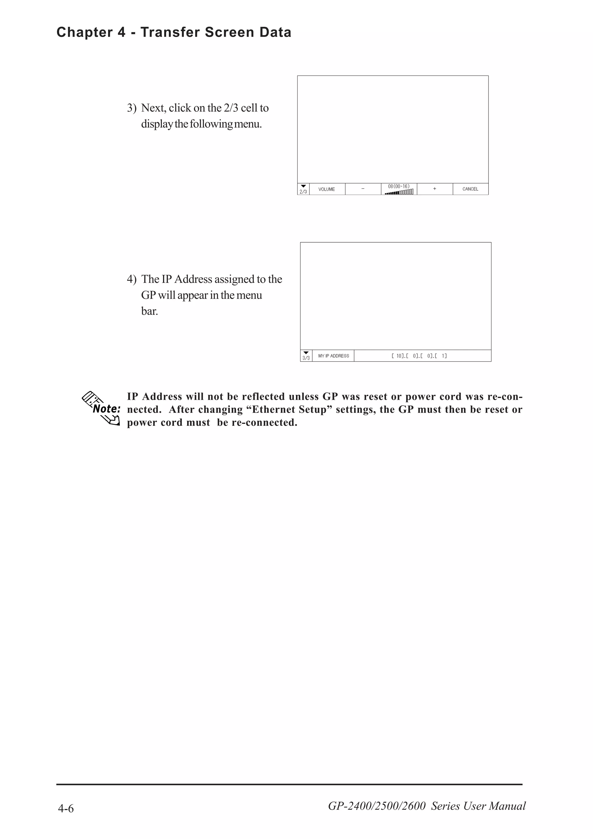
![4-7
Chapter 4 - Transfer Screen Data
GP-2400/2500/2600 Series User Manual
Dip Switches
The GP2000 allows you to use the CF Memory Loader Tool in the CF Card to set up
the GP, transfer screen data, and upload GP internal data to its internal CF Card.
• You need to transfer the CF Memory Loader Tool to the CF Card prior to using
the CF Memory Loader Tool.
GP-PRO/PBIII for Windows Operation Manual
• The CF Memory Loader Tool and Backup Data require at least 8MB of CF Card
memory. Use Digital’s CF Card “GP077-CF20 (16MB)” or “GP077-CF30 (32MB)”.
Starting the CF Memory Loader Tool
There are two methods for starting this program via the CF Card.
1. Menu Bar: Using the GP’s [CF BOOT] menu
Insert the CF Card with the CF Memory Loader Tool saved into the GP and touch the
menu screen’s [CF BOOT] selection. The GP will be reset, and after it restarts, the CF
card’s “CF Memory Loader Tool” will start.
For how to display the Menu bar, refer to 6.4.3 ETHERNET SETUP
When you finish using the CF Memory Loader Tool, turn OFF this dip switch.
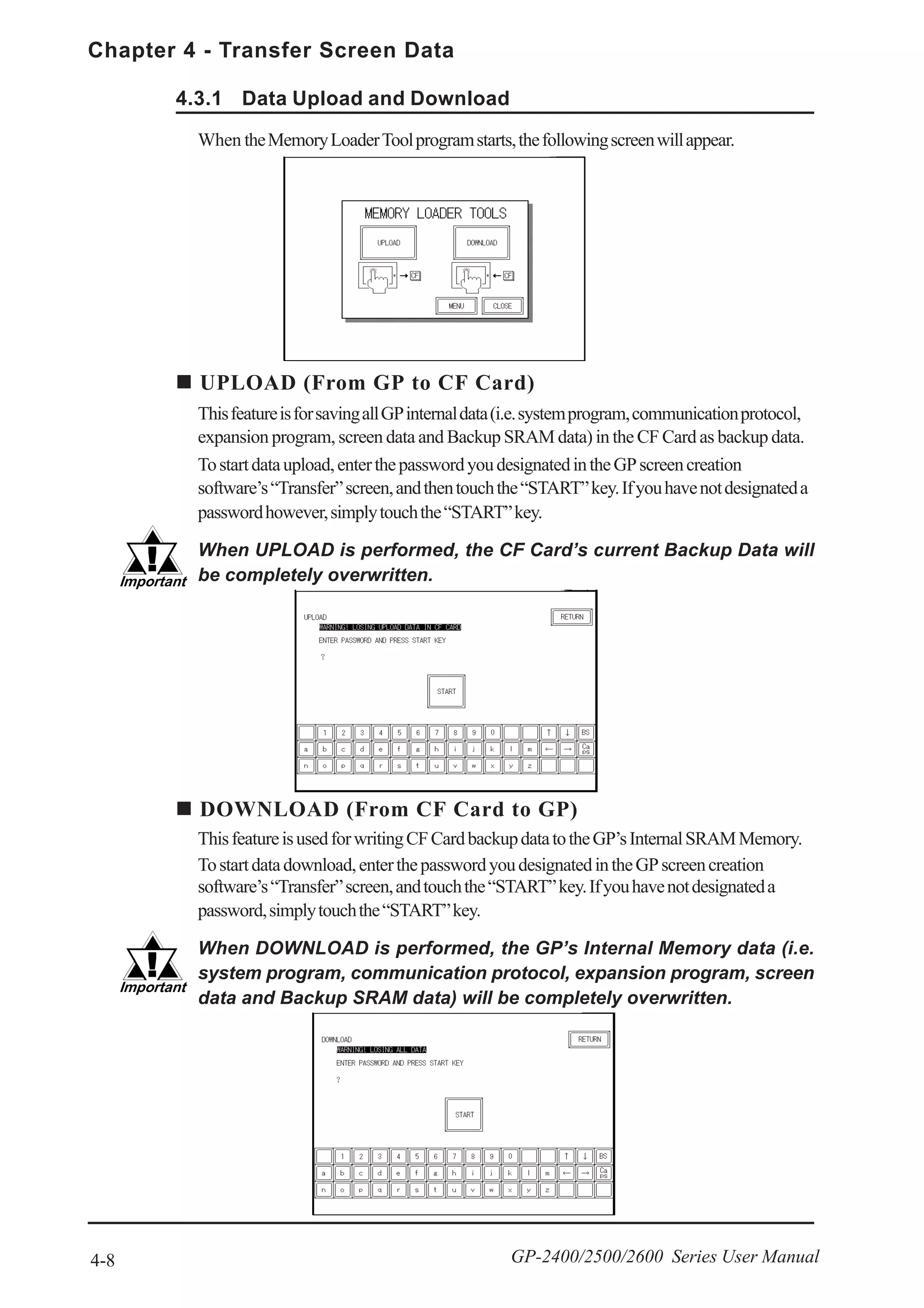
4.3 CF Memory Loader Tool
2. GP Dip Switches: Forced Start via GP Dip Switches
You can also use the Dip Switches on the rear of the GP, next to the CF Card Slot. If
you turn ON Dip Switch No.1 (raise it) and then connect the GP unit’s power cord, the
“CFMemoryLoaderTool”willautomaticallystart.
GP-2400 Series
CF Card Slot
close-up diagram
GP-2500/2600 Series
CF Card Slot
close-up diagram](https://image.slidesharecdn.com/gp2400-2500-2600manual-150602072814-lva1-app6891/75/Proface-GP2400-GP2500-GP2501-GP2600-manual-72-2048.jpg)
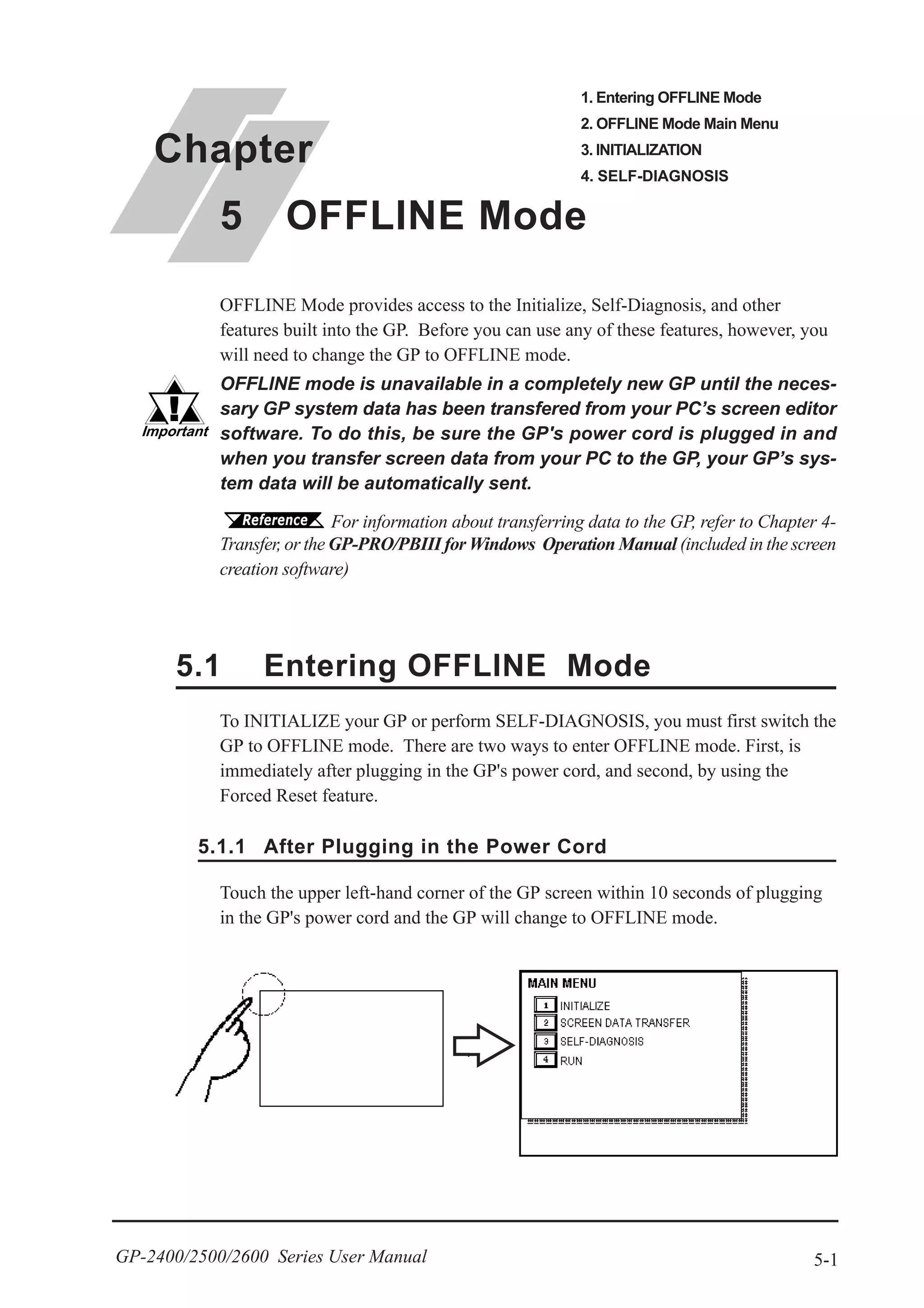
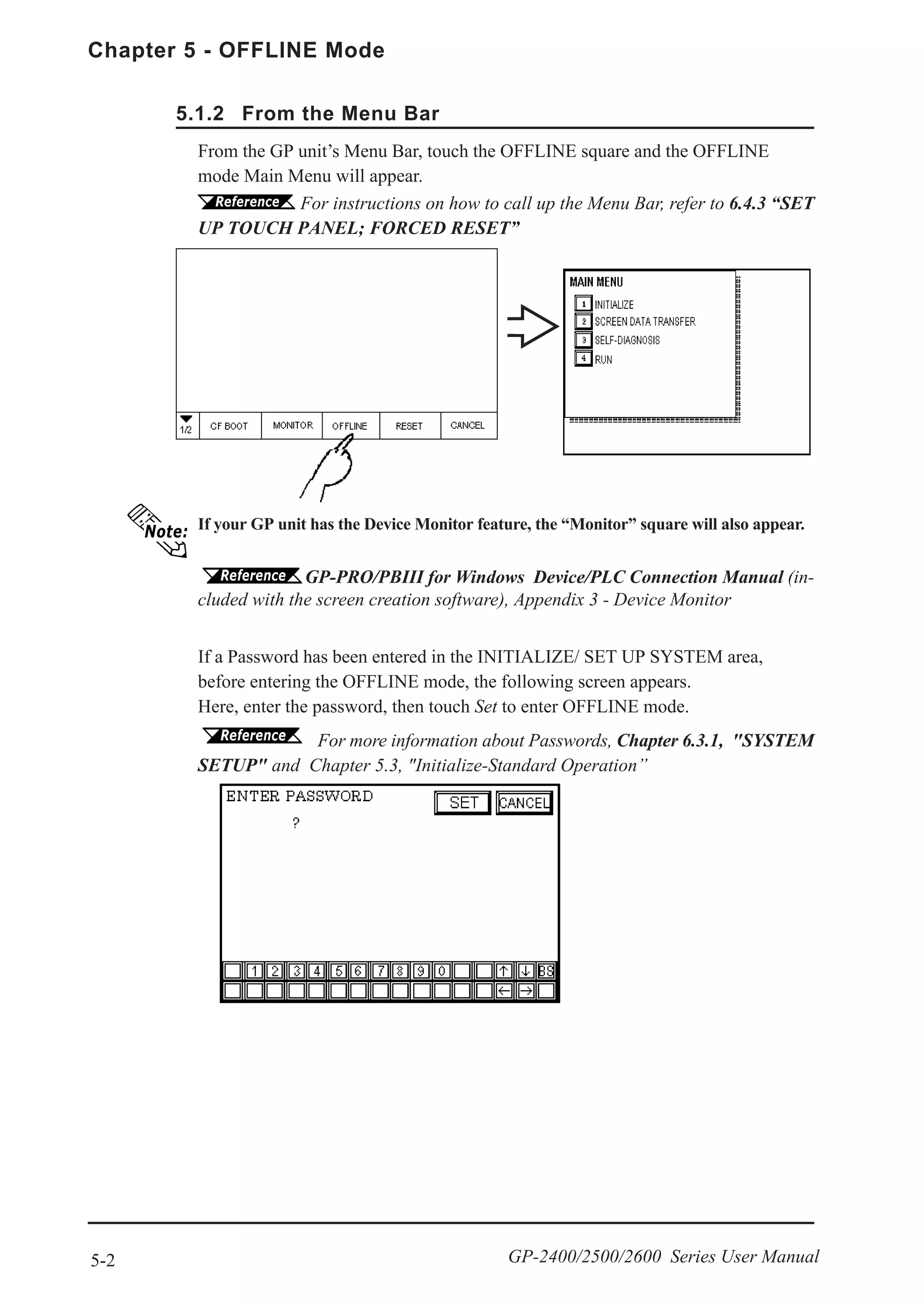

![5-5
Chapter 5 - OFFLINE Mode
GP-2400/2500/2600 Series User Manual
After All Setting Data is Entered
Touch the top-left [SET] key.
If you wish to exit the screen without saving the changes, touch the [CANCEL]
key.
Return To Previous Screen
Touch the title of the screen you would like to return to.
E.g. To return to the MAIN MENU from the SYS.ENVIRONMENT screen,
simply touch the MAIN MENU title.
• Press the [SET] key to write the Setup
conditions to the Internal FEEPROM,
which will require a short period of
time. Until this processing is com-
pleted, do not touch the screen until the
previous menu reappears.
• Press the [CANCEL] key to return to
the previous menu, without writing the
Setup conditions to the Internal
FEPROM.](https://image.slidesharecdn.com/gp2400-2500-2600manual-150602072814-lva1-app6891/75/Proface-GP2400-GP2500-GP2501-GP2600-manual-78-2048.jpg)
![Chapter 5 - OFFLINE Mode
5-6 GP-2400/2500/2600 Series User Manual
[CONFIRM], [START] and [CANCEL] Keys
After selecting the Self Diagnosis item, the [CONFIRM], [START], and [CAN-
CEL] keys may appear at different times at the top of the screen.
[CONFIRM] Key
Touching this key informs the GP that you have completed all the necessary steps
prior to running “Self Diagnosis”. All these steps will be shown in the GP’s
message dialogs.
[START] Key
Touch this key to start the checking process.
[CANCEL] Key
Press this key to cancel the Self-Diagnosis test. Control will then return to the
SELF-DIAGNOSIS menu.
Selecting a Sub-Display
Touch the desired the menu item and that sub-display will appear.
5.4 SELF-DIAGNOSIS](https://image.slidesharecdn.com/gp2400-2500-2600manual-150602072814-lva1-app6891/75/Proface-GP2400-GP2500-GP2501-GP2600-manual-79-2048.jpg)

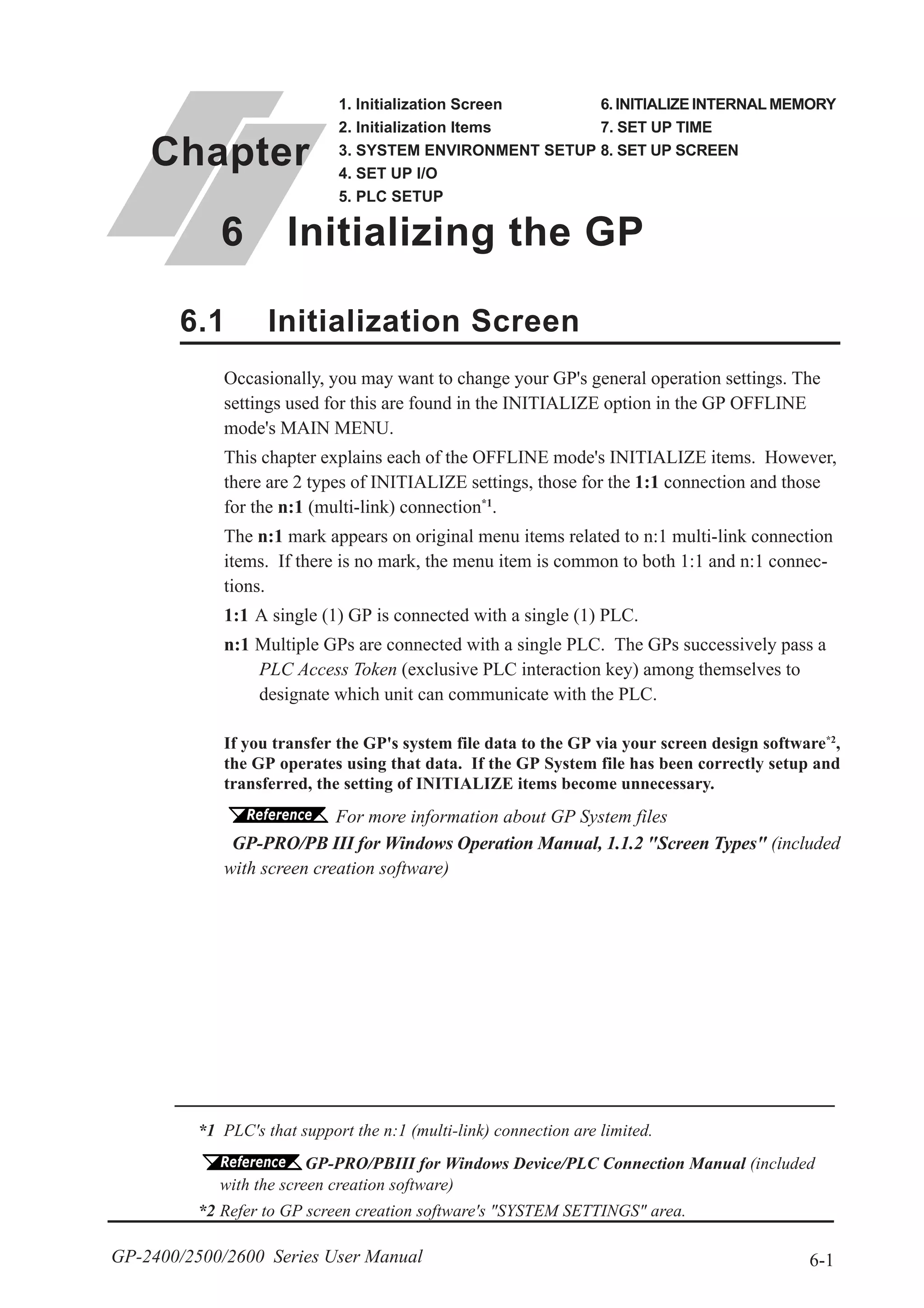
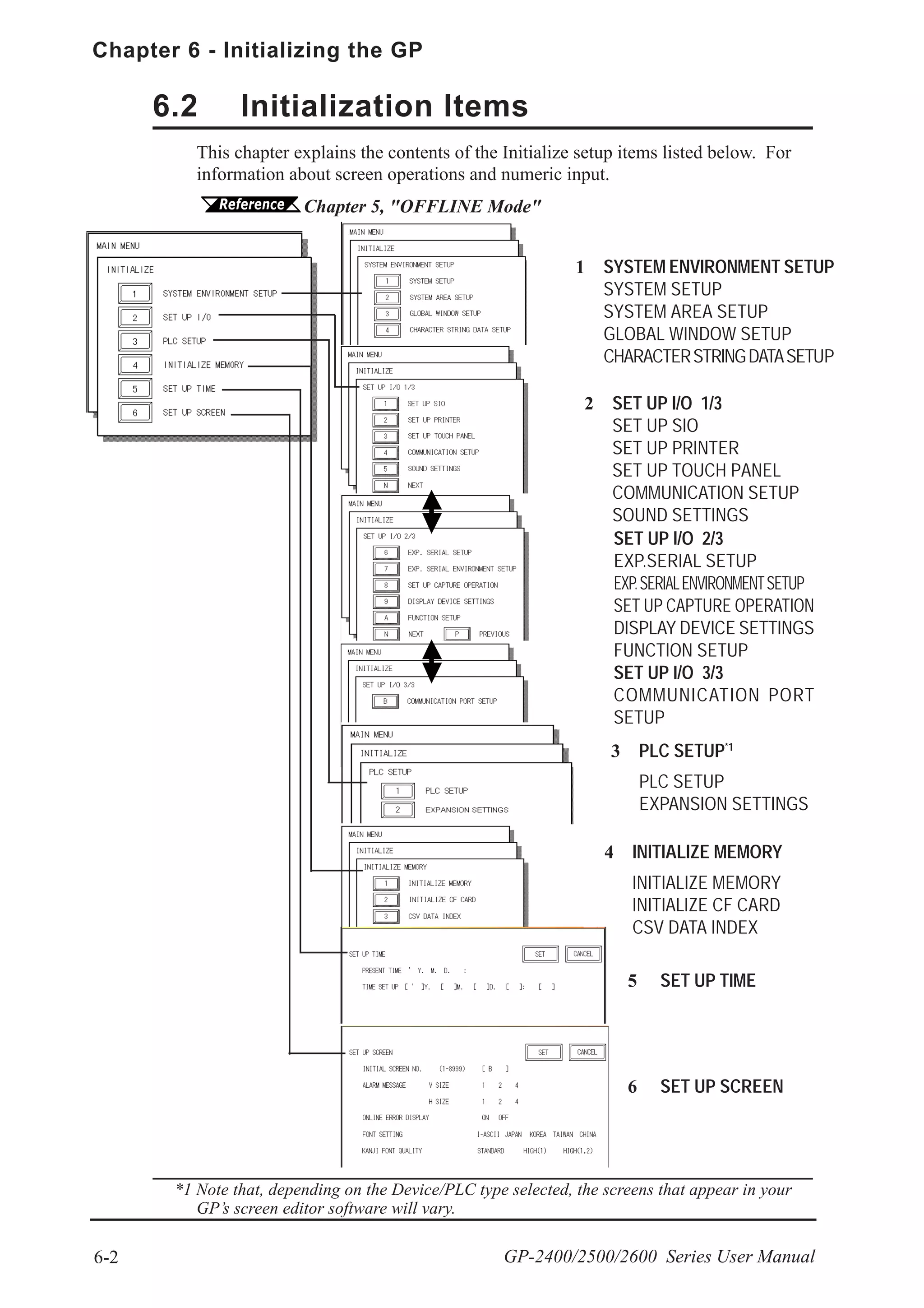
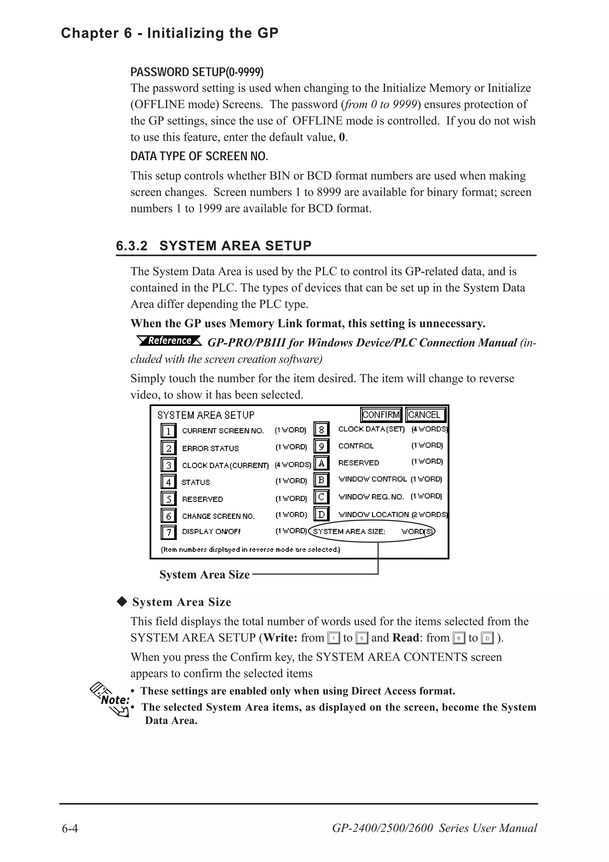
![6-5
Chapter 6 - Initializing the GP
GP-2400/2500/2600 Series User Manual
When these five items, "Current Screen Number", "Error Status", "Clock Data
(Current)", "Change Screen Number", and "Display ON/Off", have been selected,
word addresses are assigned to each item, in order, as shown here.
In the screen above, the device address used for [SET UP OPERATION
SURROUNDINGS]’s “SYSTEM AREA START DEV / START ADR” is “+0”.
Thus, in the example shown above, when the “SYSTEM AREA START DEV /
START ADR” is “D00200”, and the [CHANGE SCREEN NO.] has been desig-
nated, the address is shown as “+6” and you will need to then enter “D00206”
(i.e.“D00200” + 6) to use this address.
For details about setting “SYSTEM AREA START DEV / START ADR”, refer to
6.5.1 SET UP OPERATION SURROUNDINGS(1:1/n:1)](https://image.slidesharecdn.com/gp2400-2500-2600manual-150602072814-lva1-app6891/75/Proface-GP2400-GP2500-GP2501-GP2600-manual-86-2048.jpg)


![6-10
Chapter 6 - Initializing the GP
GP-2400/2500/2600 Series User Manual
This menu runs the settings related to Device/PLC communication. Be sure to
match the settings listed below with the SIO setup on the Host (PLC). The settings
will vary depending on the Device/PLC type.
GP-PRO/PBIII for Windows Device/PLC Connection Manual (in-
cluded with screen creation software)
If you have selected "YES" for the [SERIAL I/F CHANGE] on the [COMMUNICA-
TION PORT SETUP] screen, or "Yes" for the [Serial I/F Switch] settings in the
[Change Extend SIO Type] command, in the GP Screen Editor's [Project] menu, do
not enter all of the settings related to device communication using the Extended SIO
Script Protocol here. ([SET UP SIO] screen) These settings are required to set
using the [EXPANSION SERIAL COMMUNICATION SETUP] screen.
6.4.6 EXPANSION SERIAL COMMUNICATION SETUP
This section describes the communication setup with the Host (PLC) and the setup
for any peripheral equipment. The SET UP I/O menu includes the SET UP SIO,
SET UP PRINTER, SET UP TOUCH PANEL, COMMUNICATION SETUP,
SOUND SETTINGS, EXPANSION SERIAL SETUP, EXPANSION SERIAL
ENVIRONMENT SETUP, SETUP CAPTURE OPERATION, DISPLAY DE-
VICE SETTINGS, FUNCTION SETUP, and COMMUNICATION PORT SETUP
menus.
COMMUNICATION RATE
The COMMUNICATION RATE (baud rate) is the data communication speed,
measured in bits per second (bps), between the GP and PLC. Match the COM-
MUNICATION RATE values in both the PLC and GP. Depending on the rate
selected, certain PLCs may not be able to be used.
GP-PRO/PBIII for Windows Device/PLC Connection Manual
DATA LENGTH/STOP BIT
For data communication, the DATA LENGTH must be set up as 7-bit or 8-bit
data, and set up also the STOP BIT as either a 1-bit or 2-bit value.
PARITY
Set up whether no parity check, or an odd or even number parity check will take
place during communication.
6.4 SET UP I/O
6.4.1 SET UP SIO](https://image.slidesharecdn.com/gp2400-2500-2600manual-150602072814-lva1-app6891/75/Proface-GP2400-GP2500-GP2501-GP2600-manual-91-2048.jpg)
![6-11
Chapter 6 - Initializing the GP
GP-2400/2500/2600 Series User Manual
CONTROL
CONTROL prevents the overflow of data sent and received. Select either XON/
XOFF control or ER (DTR) control.
COMMUNICATION FORMAT
Select one of the following options for the communication format: RS-232C, RS-
422 (4 line), or RS-422 (2 line).
• When using an RS422 cable and the Memory Link format, be sure to select the
4-line option.
GP-PRO/PBIII for Windows Device/PLC Connection Manual
(included with screen creation software)
• If you have selected "YES" for the [SERIAL I/F CHANGE] on the [COMMUNI-
CATION PORT SETUP] screen, or "Yes" for the [Serial I/F Switch] settings in
the [Change Extend SIO Type] command, in the GP Screen Editor's [Project]
menu, be sure to select RS-232C.](https://image.slidesharecdn.com/gp2400-2500-2600manual-150602072814-lva1-app6891/75/Proface-GP2400-GP2500-GP2501-GP2600-manual-92-2048.jpg)
![6-12
Chapter 6 - Initializing the GP
GP-2400/2500/2600 Series User Manual
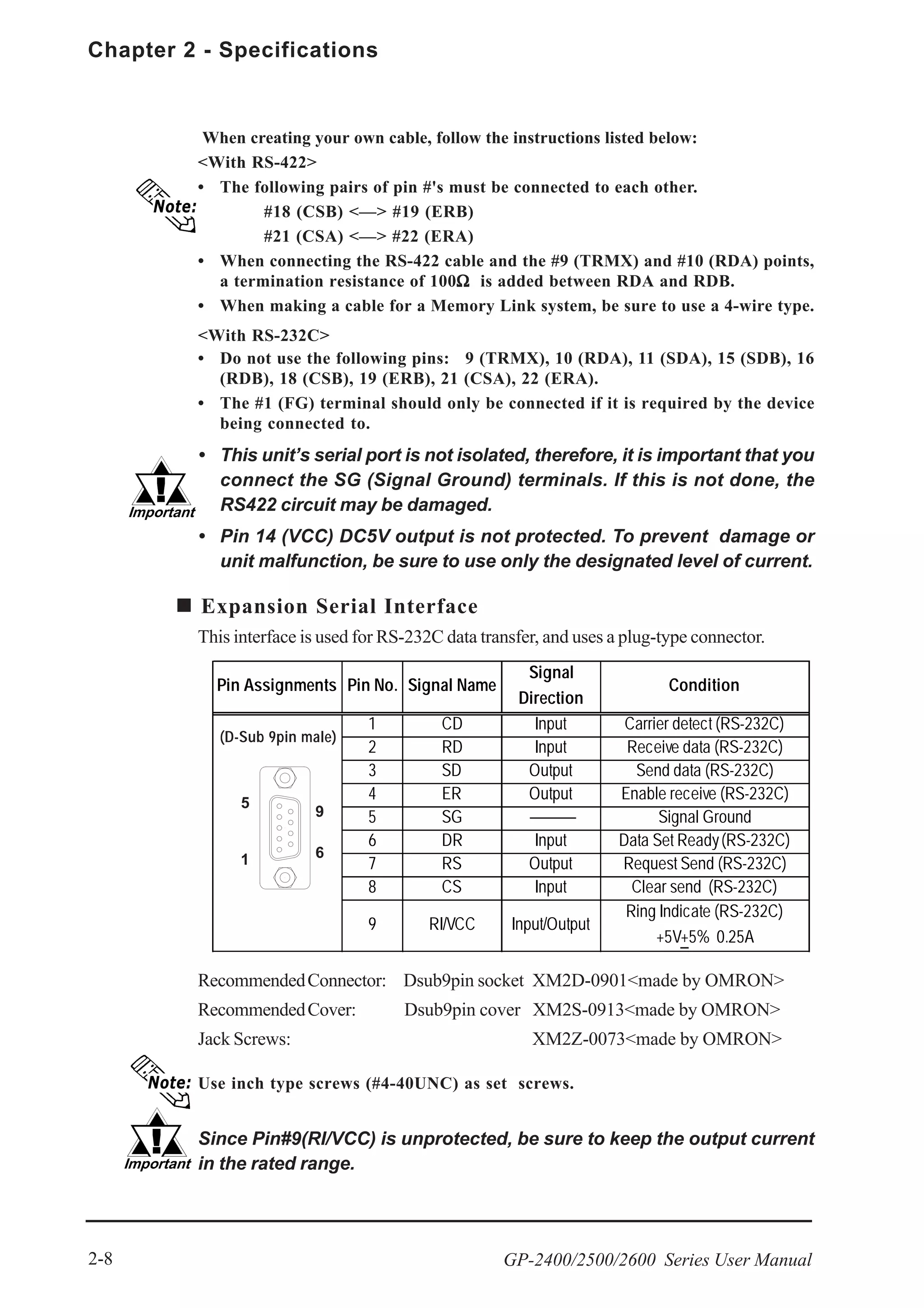
6.4.2 SET UP PRINTER
PRINTER TYPE
Printers that are compatible with NECPC-PR201/PL , EPSON ESC/P24-J84(C),
HP Laser Jet PCL 4 commands, EPSON PM/Stylus (6-color ink), and EPSON
Stylus (4-color ink) printers can be used.
• There is no difference in the quality and printing speed between EPSON ESC/P
(High Speed) and EPSON ESC/P (High Quality) when the GP (corresponding to
64 colors or more) is used to print out hard copy of screen images.
• Using EPSON PM/Stylus (6-color ink), EPSON Stylus (4-color ink) printers, GP-
PRO/PBIII for Windows Ver.6.2 or later is required. For details,
EPSON PM Series / EPSON Stylus Series
PRINT
Two selections [GREY SCALING] and [COLOR] are available. If you select
[GREY SCALING], the same pattern will be applied to:
• Blue and Green • Light blue and Red • Purple and Yellow
• Since HP LaserJet Series printers do not support color printing, be sure to desig-
nate [GREY SCALING].
• With the [GREY SCALING] feature, printing patterns are reduced to 5 levels of
gray from 256 or 64 colors.
Colors that do not appear in the printout are ones that have been converted to
white.
BLACK/WHITE REVERSE
This setting is used for reversing the background and display color black/white
color attributes. When the color is reversed, the background color is printed as
black and the character color is printed as white.
<e.g.> When the background color is black and the display color is white.
When “BLACK/WHITE REVERSE” is selected.
When “BLACK/WHITE REVERSE” is not selected.
This setting is used to designate the type of printer that will be connected to the GP.
A
A](https://image.slidesharecdn.com/gp2400-2500-2600manual-150602072814-lva1-app6891/75/Proface-GP2400-GP2500-GP2501-GP2600-manual-93-2048.jpg)
![6-13
Chapter 6 - Initializing the GP
GP-2400/2500/2600 Series User Manual
This setting is enabled only when a screen display is printed. Alarm or Recovery data
output is printed always as black, regardless of the setting selected.
HARD COPY ORIENTATION (available with GP-2600T only)
This setting designates the direction of the screen copy printout (horizontal or
vertical). This setting is available with the GP-2600T unit only.
EPSON PM/Stylus (6-color ink) and EPSON Stylus (4-color ink) models do not sup-
port "Vertical” printing. When "Vertical" is selected, printing is not performed cor-
rectly.
EPSON PM Series / EPSON Stylus Series
Restrictions for using EPSON PM / EPSON Stylus Series printers
• EPSON PM/Stylus (6-color ink) and EPSON Stylus (4-color ink) printers do
not support "Vertical” printing for "HARD COPY ORIENTATION" (screen
copy printout.)
• When printing using an EPSON PM/Stylus (6-color) or an EPSON Stylus (4-
color) printer, GP screen updating (tag processing, etc.) will be slower.
• Since OFFLINE Self-diagnosis (Printer I/F Check) is used only for ASCII code
output, it will not produce a correct printout.
• A magnification value of 1 to 4 can be specified while printing out screen hard
copy. With GP-2600T units, a magnification value of 4 may cause the printout
to exceed the width of an A4 size paper.
• When screen data printout uses levels of shading, printout from these printers
will differ from a different type printer (PR201, etc.). This is because colors are
recognized based on shading level patterns and not on the density of shading.
Extension Settings
When specifying EPSON PM/Stylus (6-color) or EPSON Stylus (4-color) as
"PRINTER TYPE", "PRINT MAGFNIFY" feature for screen data printout can be
specified in the [SET UP PRINTER (EXT-SET)] screen.
Specify either EPSON PM/Stylus (6-color) or EPSON Stylus (4-color) as
"PRINTER TYPE", and touch the key.
[SET UP PRINTER (EXT-SET)] screen will appear. Touch the desired magnification.
With GP-2600T units, a magnification value of 4 may cause the printout to exceed
the width of an A4 size paper.](https://image.slidesharecdn.com/gp2400-2500-2600manual-150602072814-lva1-app6891/75/Proface-GP2400-GP2500-GP2501-GP2600-manual-94-2048.jpg)
![6-14
Chapter 6 - Initializing the GP
GP-2400/2500/2600 Series User Manual
When specifying "PRINTER TYPE", except for EPSON PM/Stylus (6-color),
EPSON Stylus (4-color) printers, touching the key causes the following
screen to appear. Touch the key, and the [SET UP PRINTER] screen will
reappear.](https://image.slidesharecdn.com/gp2400-2500-2600manual-150602072814-lva1-app6891/75/Proface-GP2400-GP2500-GP2501-GP2600-manual-95-2048.jpg)
![6-17
Chapter 6 - Initializing the GP
GP-2400/2500/2600 Series User Manual
SET UP LCD (GP-2500L only)
To reverse the screen display colors, touch SET UP LCD on the SET UP I/O
screen to change the setting from "NORMAL" to "REVERSE", and then touch the
"SET" key. The display color will be reversed and the previous screen will reap-
pear.
USE TOUCH PANEL AFTER BACKLIGHT BURNOUT
This option designates whether touch-operation is disabled or not when the back-
light burns out.
If this selection is set to [OFF], touch-operation will be disabled when the back-
light burns out, which prevents the GP from sending input signals to the PLC.
• When the backlight burns out, the Status LED's orange light turns ON, and the
System Data Area's "Status" bit 10*1
will turn ON.
• The GP-2400/2500/2600 series models use two backlights (CCFL). The GP detects
backlight burnout when one of the two backlights burns out, and disables touch-
operations.
• If the [SYSTEM RESET] option is set to [ON], only "System Reset" can still be
performed by touch-operation in case of backlight burnout.
• If the backlight burns out when the GP is OFFLINE, touch-panel operation is
enabled, regardless of these settings.
Normally, the GP unit detects a backlight burnout by monitoring the
backlight's current flow, however, the GP may fail to detect this condi-
tion, depending on the type of backlight problem, and also the GP may
detect the condition before the backlight burns out.
*1 Bit +6 (when using the Direct Access method), and bit +11 (when using the Memory
Link method), will turn ON.
GP-PRO/PBIII for Windows Device/PLC Connection Manual (in-
cluded with screen creation software)](https://image.slidesharecdn.com/gp2400-2500-2600manual-150602072814-lva1-app6891/75/Proface-GP2400-GP2500-GP2501-GP2600-manual-98-2048.jpg)
![6-19
Chapter 6 - Initializing the GP
GP-2400/2500/2600 Series User Manual
6.4.6 EXPANSION SERIAL COMMUNICATION SETUP
The following explains the setup for communicating with a device connected to
the Expansion Serial Interface. This setup screen will not display unless the
communication protocol for the Expansion Serial Interface (specified with “SET
UP EXPANSION SIO” of the GP screen creation software package) is transferred
to the GP.
If you have selected "YES" for the [SERIAL I/F CHANGE] on the [COM-
MUNICATION PORT SETUP] screen, or "Yes" for the [Serial I/F Switch]
settings [Change Extend SIO Type] command, in the GP Screen Edi-
tor' [Project] menu, enter all of the settings related to device communi-
cation using the Extended SIO Script Protocol here, [EXPANSION SE-
RIAL COMMUNICATION SETUP] screen.
COMMUNICATION RATE
The COMMUNICATION RATE refer to the data communication speed, measured
in bits per second (bps), between the GP and the device connected to the Expan-
sion Serial Interface.
The supported communication rates vary depending on the connected device.
Refer to the instruction manual of the connected device for more information. The
initial setting varies depending on the communication protocol for the Expansion
Serial Interface being transferred.
DATA LENGTH
Set the DATA LENGTH to 7-bit or 8-bit data.
STOP BIT
Set the STOP BIT to either 1- or 2-bit.
PARITY
Set the parity to no parity (OFF), or an ODD or EVEN parity check.](https://image.slidesharecdn.com/gp2400-2500-2600manual-150602072814-lva1-app6891/75/Proface-GP2400-GP2500-GP2501-GP2600-manual-100-2048.jpg)

![Chapter 6 - Initializing the GP
6-24 GP-2400/2500/2600 Series User Manual
6.4.11 COMMUNICATION PORT SETUP
This screen allows you to set up the connection environment of the GP's commu-
nication port.
SERIAL I/F CHANGE
Selecting "YES (COM1 <->COM2)" designates that the communication used for the
Extended SIO Script Protocol starts at the Serial I/F (COM1). Also, the communication
used for the device/PLC starts at the Expansion Serial I/F (COM2).
In OFFLINE mode, the SERIAL I/F CHANGE setting is set to "NO".
• After selecting "YES (COM1 <->COM2)", enter all of the settings related to de-
vice communication using the Extended SIO Script Protocol, [EXPANSION SE-
RIAL COMMUNICATION SETUP] screen. Enter all of the settings related to
Device/PLC communication, [SETUP SIO] screen.
• To use the "SERIAL I/F CHANGE" feature, the system of GP-PRO/PB III for
Windows Ver.6.2 or later is required to be transferred to the GP.
RI/VCC (COM2)
This setting designates if the Serial Interface's #9 pin is used for RI or for VCC.](https://image.slidesharecdn.com/gp2400-2500-2600manual-150602072814-lva1-app6891/75/Proface-GP2400-GP2500-GP2501-GP2600-manual-105-2048.jpg)


![Chapter 6 - Initializing the GP
6-30 GP-2400/2500/2600 Series User Manual
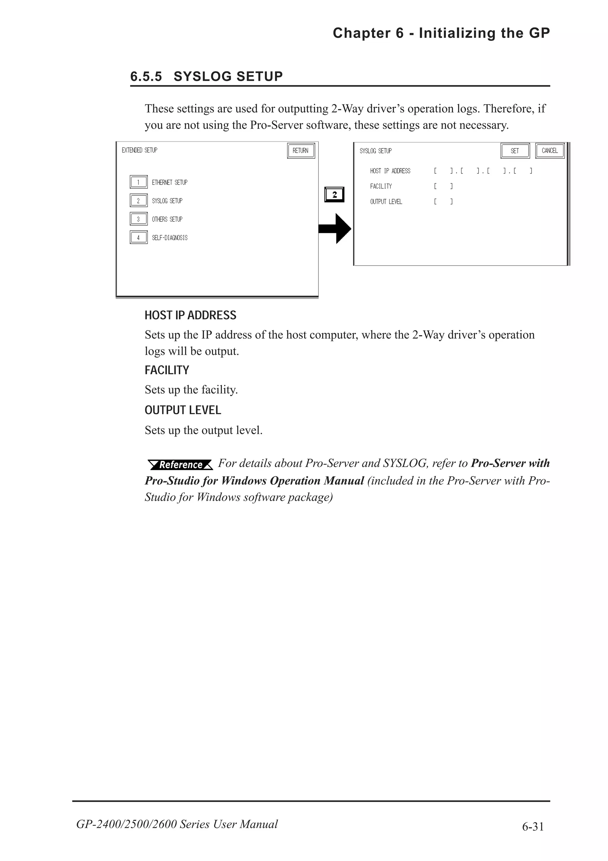
6.5.4 ETHERNET SETUP
This menu is for Ethernet settings. This information is used as setting data during
GP setup or screen transfer, or, if the Pro-Server software is used, for the 2-Way
Driver.
MY IP ADDRESS
Sets up the GP’s IP address. The IP address is 32 bits and designated in four 8-bit
units, entered in decimal.
To use Ethernet networking, click on [Initial Settings], [PLC Setup], [PLC Setup]
and [Ethernet Setup].
SUBNET MASK
Sets the subnet mask. If you are not using a subnet mask, designate “0”.
To use Ethernet networking, click on [Initial Settings], [PLC Setup], [PLC Setup]
and [Ethernet Setup].
MY PORT NO.
Sets the 2-Way Driver Port No. using a value from 1024 to 65535. Starting from
the value entered here, a toatl of 10 consecutive ports can be used. The default
setting is [8000].
To use Ethernet networking, click on [Initial Settings], [PLC Setup], [PLC Setup]
and [Ethernet Setup] and select the corresponding Ethernet protocol Port No.
GATEWAY
Sets up the gateway’s IP address. Only a single gateway can be set up. If you are
not using a gateway, enter “0”.
• Enter the “ETHERNET SETUP” settings after receiving information
from your network's system administrator.
• Be sure to enter a unique IP address, not one used for other GPs or
by the host.](https://image.slidesharecdn.com/gp2400-2500-2600manual-150602072814-lva1-app6891/75/Proface-GP2400-GP2500-GP2501-GP2600-manual-111-2048.jpg)
![6-33
Chapter 6 - Initializing the GP
GP-2400/2500/2600 Series User Manual
6.5.7 SELF DIAGNOSIS
When there is no error detected, the message “OK” will appear. If an error is
detected, the message “NG” will appear.
Be sure that this Self Diagnosis program is used only for the Ethernet operation. If
you wish to run the general Self Diagnosis program, use [Main Menu]’s [Self
Diagnosis] feature.
7.3 Self Diagnosis
Runs the Self Diagnosis program for the Ethernet operation. The GP must be
connected to the Ethernet network prior to running this program.](https://image.slidesharecdn.com/gp2400-2500-2600manual-150602072814-lva1-app6891/75/Proface-GP2400-GP2500-GP2501-GP2600-manual-114-2048.jpg)
![Chapter 6 - Initializing the GP
6-34 GP-2400/2500/2600 Series User Manual
6.6 INITIALIZE INTERNAL MEMORY
6.6.1 INITIALIZE GP MEMORY
6.6.2 INITIALIZE CF CARD
Initializes the CF Card. Enter the common password “1101” or the password you
designated in the “SYSTEM SET UP” menu.
For details about entering the password’s numeric values, refer to
5.3 INITIALIZATION
This section explains how to initialize the GP’s internal data or a CF card inserted in
the GP. Select one of the menu items, [INITIALIZE MEMORY] , [INITIALIZE CF
CARD] and [CSV DATA INDEX] selections in the [INITIALIZE MEMORY] menu.
To initialize the GP internal memory, enter the common password 1101, or the
password entered in the SYSTEM SET UP screen.
Chapter 5.3, "INITIALIZE-Standard Operation"
The time required for Initialization is between 10 and 20 seconds.
• You cannot cancel the Initialization procedure after pressing the Start key.
• AIl data in SRAM will be erased.
• Initialization does not erase the SYSTEM SET UP, the SIO protocol, or
the internal clock settings.
Deletes all data in the CF Card installed in the GP.
Initialization cannot be canceled once the START switch is touched.](https://image.slidesharecdn.com/gp2400-2500-2600manual-150602072814-lva1-app6891/75/Proface-GP2400-GP2500-GP2501-GP2600-manual-115-2048.jpg)
![6-35
Chapter 6 - Initializing the GP
GP-2400/2500/2600 Series User Manual
6.6.3 CSV DATA INDEX
Specific data-transfer CSV files (ZR*****.CSV) on the CF Card can be trans-
ferred from the CF Card directly to the PLC (filing) or from the PLC directly to
the CF Card (logging). For the details about the CSV Data Transfer Function,
GP-PRO/PB III for Windows Tag Reference Manual.
Here creates the index file of the CSV files that are saved into the CF card with
the CSV data transfer function.
Touch the [START] key, then the operation to create the index file will start.
Do not open the CF card cover during the operation to create the index
file. The data may be damaged.
Too many number of CSV files may cause a time loss for creating the index file. It
will take about 10 minutes for creating an index file of the 4,000 CSV files.
If you touch the [CANCEL] key during the operation to create the index file, the
operation will stop, then the following screen will appear.
CONTINUE
The operation restarts. When the message "CREATED INDEX FILE. PLEASE
PRESS END KEY" appears, finish the program.
END
Deletes the creating index file, then the [INITIALIZE MEMORY] screen will
reappear.](https://image.slidesharecdn.com/gp2400-2500-2600manual-150602072814-lva1-app6891/75/Proface-GP2400-GP2500-GP2501-GP2600-manual-116-2048.jpg)

![Chapter 6 - Initializing the GP
6-38 GP-2400/2500/2600 Series User Manual
FONT SETTING
Selects the font type displayed on the GP screen during operation.
KANJI FONT QUALITY
Designates the font display quality for enlarged characters.
When [FONT SETTING] is set to [JAPAN]
Single-byte characters will remain 8x16-dot characters when they are enlarged.
Double-byte characters are displayed as:
[Standard] Here, characters are displayed using 16x16-dot “blocks”. When
enlarged, this font will remain a 16x16-dot character. (Compat-
ible with GP-*30 series units.)
[HIGH] When enlarged to double size, Level 1 JIS Kanji Code charac-
ters are displayed as 32x32-dot characters. Level 2 JIS Kanji
Code characters remain 16x16-dot characters. (Compatible with
GP-*50 series and GP-70 series units.)
[1,2] When enlarged to double size, both Level 1 and Level 2 JIS
Kanji Code characters are displayed as 32x32-dot characters.
When [FONT SETTING] is set to any other type (i.e. CHINESE, I-
ASCII, KOREA or TAIWAN)
[Standard] Half-size (single-byte) characters are displayed as 16x8-dot
characters. Full-size characters, regardless of the display size
used, will always be displayed as 16x16-dot characters. When
enlarged, this font will stay as 16x16-dot character. (Compatible
with GP-*30 Series units)
[HIGH(1)] All half-size (single-byte) characters (ASCII code: 21h to 7Dh,
i.e. alphanumeric characters) except “ ^ ” and “ ‘ “ will display
as high quality characters.
• 16x16-dot or larger characters will display as high quality
16x16 fonts.
• 32x32 or larger characters will display as high quality 32x32
fonts.
Full-sized (double-byte) characters will display as 16x16-dot
characters and remain 16x16-dot characters when enlarged.
[HIGH(1,2)] All single-byte characters (ASCII code: 21h to 7Dh, i.e. alpha-
numeric characters) except “ ^ ” and “ ‘ “ will display as high
quality characters.
• When 16x16 dots are used for a character, it will display as a
high quality 16x16 character.
• When 32x32 or larger dots are used for a character, the
character will display as a high quality 32x32-character.
Full-sized (double-byte) characters (i.e. [KOREA], [TAIWAN-
ESE] and [CHINESE]) will display as 32x32-dot characters
when enlarged to 32x32-dot or larger characters.](https://image.slidesharecdn.com/gp2400-2500-2600manual-150602072814-lva1-app6891/75/Proface-GP2400-GP2500-GP2501-GP2600-manual-119-2048.jpg)

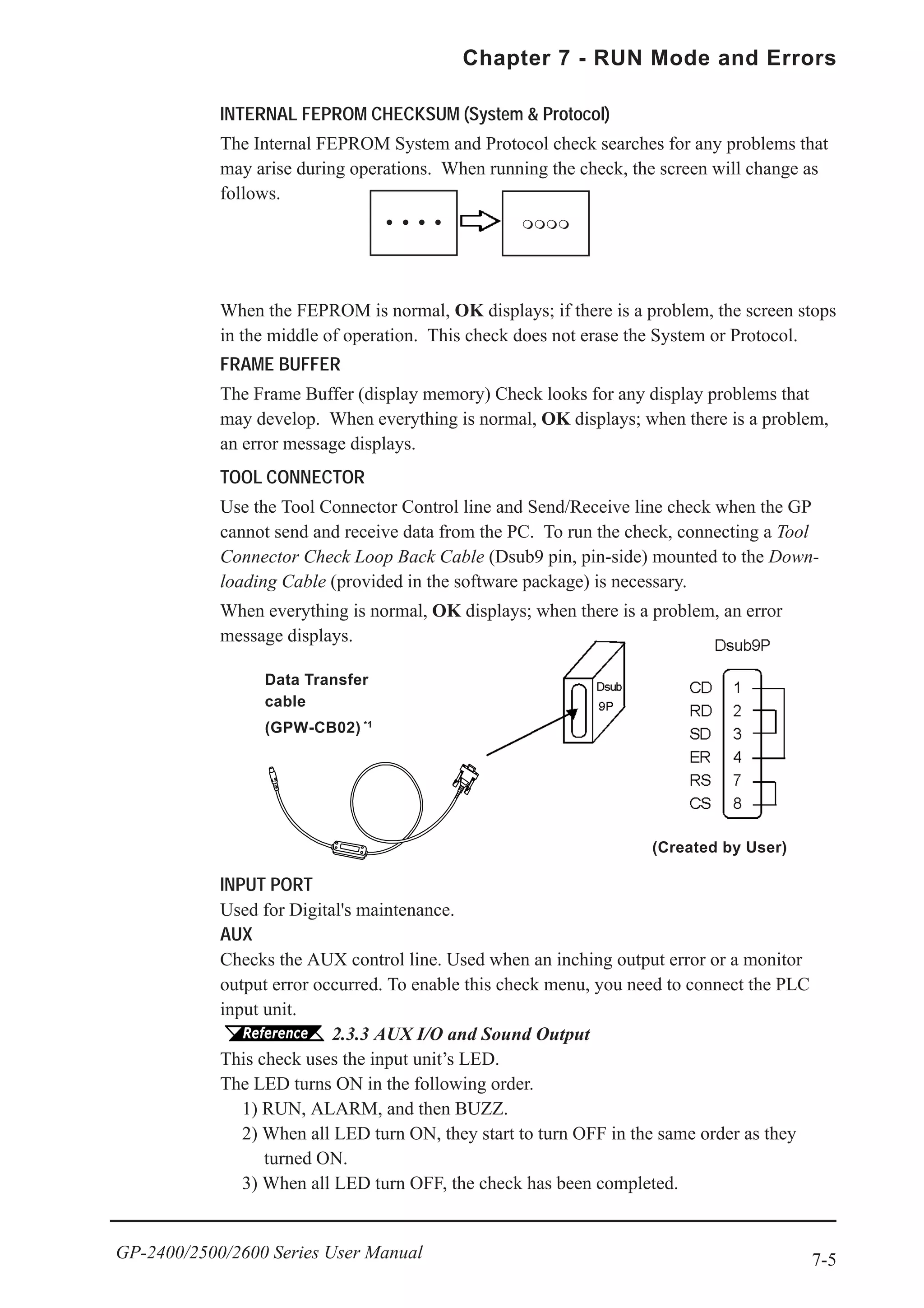
![7-4
Chapter 7 - RUN Mode and Errors
GP-2400/2500/2600 Series User Manual
CHARACTER PATTERN
Checks each font’s pattern and kanji-characters’ ROM. Used when kanji-charac-
ters do not display. If there is no error, the message [OK] will appear, if there is an
error, the message [NG] will appear.
DISPLAY PATTERN
Used when the buzzer will not sound and when the device contents will not
display correctly to check the drawing function. It does this by running checks on
the various screen pattern displays (8 screens), the ON/OFF Display, and
KANJIROM CHECKSUM. When the ON/OFF Display is checked, the Buzzer
ON/OFF check is run simultaneously. If KANJIROM CHECKSUM is normal,
OK displays; if there is a problem, NG displays.
TOUCH PANEL
Touch Panel check. Checks if each touch cell highlights when pressed.
INTERNAL FEPROM (Display Area)
• If you run this check menu, all screen data that have been created
will be deleted. Therefore, be sure to back up data prior to running
this check.
• When this check menu is completed, you need to initialize the inter-
nal memory (FEPROM).
7.2.2 SELF-DIAGNOSIS - Details
This section explains the contents of SELF-DIAGNOSIS. For information on
how to operate the Screen, Chapter 5, "OFFLINE Mode"; for
information about how to set up the Special Tools, Chapter 3,
"Installation and Wiring".
This menu is used for checking the internal FEPROM. Use this check menu when
an error related to screen display occurred. When using this check menu, you need
to enter the password *1.
While checking, the screen display will change in the following order.
If there is no error, the message [OK] will appear, if there is an error, an error
message will appear.
The number of the symbol marks (i.e. “OOOO”, etc.) shown on the screen may
vary depending on the GP type.
The symbol mark “O” indicates the GP is operating the erase checking.
The symbol mark “*” indicates the GP is operating the R/W checking.
*1 Enter either the password you have designated in the “INITIALIZE” screen or the
common password “1101”.
****](https://image.slidesharecdn.com/gp2400-2500-2600manual-150602072814-lva1-app6891/75/Proface-GP2400-GP2500-GP2501-GP2600-manual-123-2048.jpg)
![7-6
Chapter 7 - RUN Mode and Errors
GP-2400/2500/2600 Series User Manual
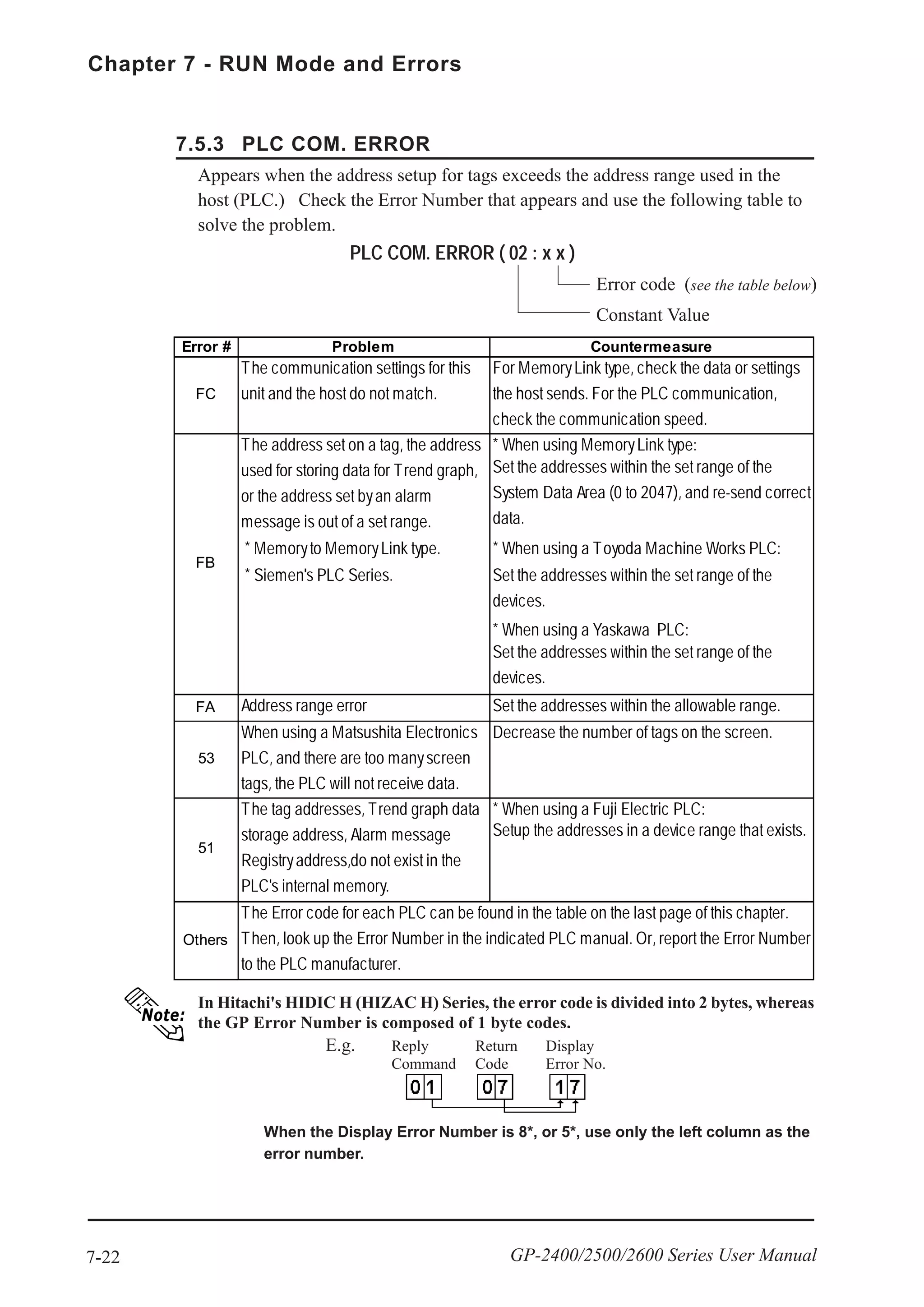
PRINTER I/F
Checks the printer I/F. Used when the printer does not function properly. You need
to connect the printer prior to using this checking menu.
Connecting the printer buffer may cause an error, therefore, connect the GP and
the printer directly.
If there is no error, (ASCII Code: 20 to 7D<HEX> and A0 to DF<HEX>) will be
output (printed) and the message [OK] will appear on the screen. If there is an
error, an error message will appear.
SIO CHECK
Checks the RS-232C and RS-422 SIO lines for areas where communication
problems develop. In the menu, select which check to run. To run the check,
connecting the SIO cable is necessary. If all is normal, OK displays; if there is a
problem, an error message appears.
The SIO cable wiring is as shown below. (RS-232C, RS-422 common)
CF CARD
Checks the CF Card’s Read/Write. Prior to using this check menu, you need to
insert the CF Card in the GP. The CF Card needs to have more than 1K bytes
usable space. If there is no error, the message [OK] will appear. If there is an error,
an error message will appear.
CF CARD CHECKSUM
Takes the Checksum of the CF Card’s files and operates the check. Prior to using
this check menu, you need to insert the CF Card in the GP.
This check menu can check the following files.
• Filing Data
• CF Card’s Image Data
• CF Card’s Sound Data
When the check is finished, the following items will appear on the screen.
• The number of checked files
• The number of files that have an error
• The file name where the most recent error occurred](https://image.slidesharecdn.com/gp2400-2500-2600manual-150602072814-lva1-app6891/75/Proface-GP2400-GP2500-GP2501-GP2600-manual-125-2048.jpg)
![7-7
Chapter 7 - RUN Mode and Errors
GP-2400/2500/2600 Series User Manual
SOUND I/F
Checks if Sound Output operates. Prior to using this check menu, connect the
speaker to the GP. The first three notes of the musical scale (do, re,mi) will sound.
CF CARD MEMORY LOADER FILE CHECK
Checks the CF Card’s Memory Loader Tool when it does not start. If there is no
error, the message [OK] will appear. It there is an error, the message [NG] will
appear.
EXPANSION SERIAL I/F
Checks the Send/Receive line of the Expansion Serial Interface when an abnor-
mality occurs. To run the check, you must connect the SIO cable. If all is normal,
the message [OK] appears. If there is a problem, an error message appears.
The SIO cable wiring is as shown below.
1
2
3
4
5
6
7
8
9
CD
RD
SD
ER
SG
DR
RS
CS
RI/VCC](https://image.slidesharecdn.com/gp2400-2500-2600manual-150602072814-lva1-app6891/75/Proface-GP2400-GP2500-GP2501-GP2600-manual-126-2048.jpg)


![7-19
Chapter 7 - RUN Mode and Errors
GP-2400/2500/2600 Series User Manual
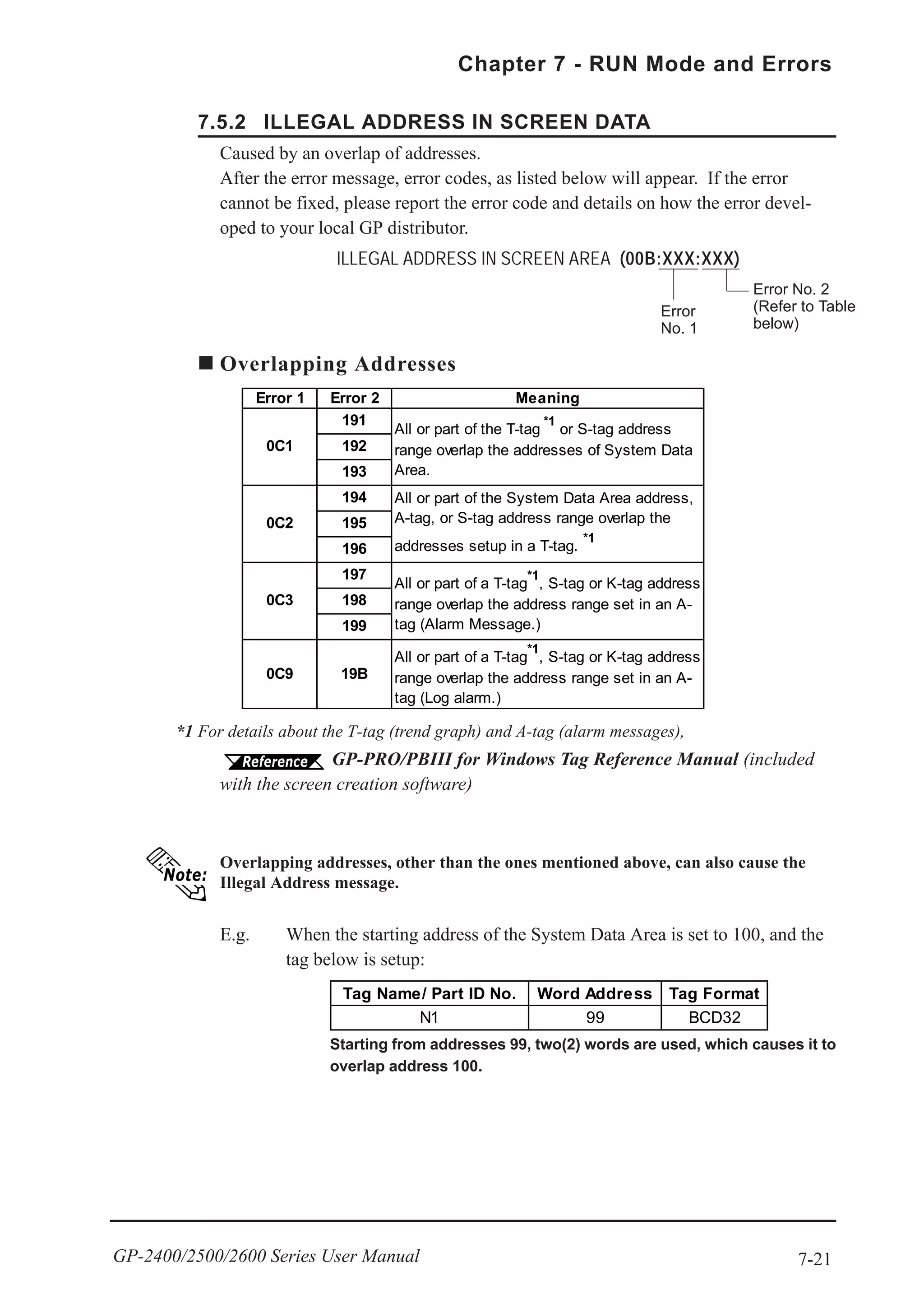
7.5 Error Message Details
7.5.1 SYSTEM ERRORS
Indicates a fault in the basic operations of the GP.
Following the error message, an error code, as shown below, will appear. Report the
error number and details on how the error developed to your local GP distributor.
SYSTEM ERROR ( 03 : x x )
An unrecoverable error occurred during screen data transfer.
03 : x x
Possible Solutions
• Check if the GP's Power Cord and the Input signal line have been wired sepa-
rately from each other.
• Check that the FG line has been grounded correctly, according to your country's
standards.
• Re-send the screen data from the PC to the GP.
• If other types of communication errors, such as [RECIEVE DATA ERROR],
[PLC COM. ERROR], have also occurred, try to correct those problems also.
7.4.1 Error Message List
If the above mentioned methods do not solve the problem, please contact your
local GP distributor.
Error No.
Constant Value
SYSTEM ERROR ( x x x : x x x : x x x )
An unrecoverable error occurred during screen data transfer.
x x x : x x x : x x x
Error No. 2
Error No. 3
Error No. 1](https://image.slidesharecdn.com/gp2400-2500-2600manual-150602072814-lva1-app6891/75/Proface-GP2400-GP2500-GP2501-GP2600-manual-138-2048.jpg)