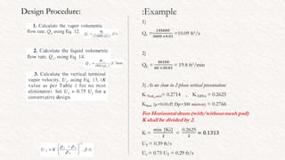
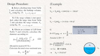
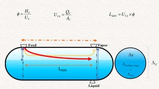
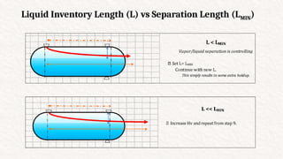
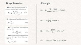
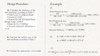
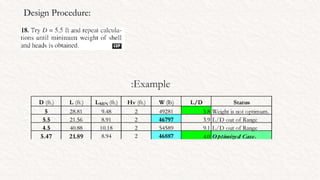
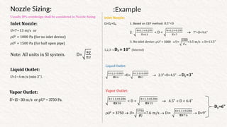
Two Phase Separator
Horizontal Type Design Procedure
Ali Farrokhzad ‫پاییز‬
1395
Jan 2017
Size a Horizontal separator with a mist eliminator
pad to separate the following mixture .
The operating pressure is 975 psig and the holdup
and surge are to be 10 min and 5 min respectively.
Use a design temperature of 650°F .
Example
:
Design Procedure: Example
:
Design Procedure: Example
:
Design Procedure: Example
:
7)
HLLL = 0.5×5+7
= 9.5 in.
8)
x = HLLL/D =0.158
From Eq. → y = 0.102 → ALLL/AT = 0.102
→ ALLL =0.102×19.63
= 2 ft2
.
7.
Design Procedure: Example
:
Liquid Inventory Length:
Av
A(holdup+surge)
+
ALLL
AT
Liquid Inventory Length (L) vs Separation Length (LMIN)
Design Procedure: Example
:
Design Procedure: Example
:
L > 1.2 ×LMIN → L >> LMIN
Type:
Calculation of thickness of Head & Shell
Design Pressure & Design Temperature
:
Reference: RULES OF THUMB: SUMMARY , Walas Click to see contents:
1. Design temperature between -20°F and 650°F is 50°F above operating temperature; higher safety
margins are used outside the given temperature range.
If -20 o
F <OT < 650 o
F → DT=OT + 50 o
F
2. The design pressure is 10% or 10-25 psi over the maximum operating pressure, whichever is greater.
The maximum operating pressure, in turn, is taken as 25 psi above the normal operation.
MOP= NOP+25 psi DP=max.{1.1×MOP , MOP+10~25 psi}
3. Design pressures of vessels operating at 0-10 psig and 600-1000°F are 40 psig.
Calculation of thickness of Head & Shell
P, design pressure, psig
Typically,
operating pressure+(15-30) psi or 10-15%, whichever
greater.
T, design temperature , o
F
Typically,
if Top > 200°F, DT=operating temperature +25-50°F.
If Top < 200°F, DT=250°F
• under 650°Fdoesnot reduce wall thickness
• if overpressure caused by boiling, should be TBP .
Allowable Stress of Alloy
Pressure Vessel Handbook-
Megyesy
Evaluate Design Temperature for the selected alloy
and then read S from the Table.
Design Procedure: Example
:
DT = 650 o
F
NOP=975 psig
→ MOP=975+25=1000 psig
→ DP=max{1000+25, 1.1×1000}=1100 psig
Alloy: SA 516 70 Carbon Steel
→From Table: 17.5 → S= 17500 psi
Let C.A. tC= 1/16 = 0.06 in. & Joint Efficiency (E) = 0.85
Head Type:
D < 15 ft. & P > 100 psig → 2:1 Elliptical
Tips:
According to Walas Rules of Thumbs
for Pressure Vessels
Corrosion allowance:
0.35 in. for known corrosive conditions,
0.15 in. for non-corrosive streams, and
0.06 in. for steam drums and air receivers.
Design Procedure: Example
:
15)
Head Thickness & Area:
Shell Thickness & Area:
Alloy plate thickness:
16)
17)
Design Procedure:
Example
:
Nozzles Orientation:
Nozzle Sizing: Example
:
→DV=6”
Vapor Outlet:
U=15~30 m/s or U
ρ 2
= 3750 Pa.
Liquid Outlet:
U=1~4 m/s (min 2”).
Home Work:
Design a Horizontal flash drum by considering below conditions.
Feed enters at 5 barg & 40 o
C.
Vapor density is 8 kg/m3
& liquid density is 780 kg/m3
.
Flow rate of feed is 12,000 kg/hr.
Feed is non corrosive, use your own assumption during sizing.
Report required data as much as possible.
Assume previous (Vertical H.W.) assumptions and compare the both
design cases.
1) Unit Feed Drum with q=40% , with Mesh pad.
2) Flare K.O. Drum with q=0 , without Mesh pad
3) Unit Feed Drum with q=40% and without mesh pad.
4) Unit Feed Drum with q=80%, with mesh pad.
5) Unit Feed Drum with q=100%, with mesh pad.
Extra Example:
Slug catcher with q=20% and 40 m3
slug volume as unit feed drum.
References
:
1. Wayne D. Monnery and William Y. Svrcek.
"Design Two-Phase Separators Within
The Right Limits"; ,University of Calgary;
October 1993. Chemical Engineering
Progress (CEP).
2. Eugene F. Megyesy. "Pressure Vessel
Handbook", 10th Edition, University of
Tulsa, 1997.
3. Stanley M. Walas, "Chemical Process
Equipment Selection and Design",
University of Kansas, 1990.

Two Phase Horizontal Separator - Design Procedure.ppsx.pptx

  • 1.
    Two Phase Separator HorizontalType Design Procedure Ali Farrokhzad ‫پاییز‬ 1395 Jan 2017
  • 4.
    Size a Horizontalseparator with a mist eliminator pad to separate the following mixture . The operating pressure is 975 psig and the holdup and surge are to be 10 min and 5 min respectively. Use a design temperature of 650°F . Example :
  • 5.
  • 6.
  • 7.
    Design Procedure: Example : 7) HLLL= 0.5×5+7 = 9.5 in. 8) x = HLLL/D =0.158 From Eq. → y = 0.102 → ALLL/AT = 0.102 → ALLL =0.102×19.63 = 2 ft2 . 7.
  • 8.
  • 9.
  • 10.
  • 11.
    Liquid Inventory Length(L) vs Separation Length (LMIN)
  • 12.
    Liquid Inventory Length(L) vs Separation Length (LMIN)
  • 13.
  • 14.
    Design Procedure: Example : L> 1.2 ×LMIN → L >> LMIN Type:
  • 15.
    Calculation of thicknessof Head & Shell Design Pressure & Design Temperature : Reference: RULES OF THUMB: SUMMARY , Walas Click to see contents: 1. Design temperature between -20°F and 650°F is 50°F above operating temperature; higher safety margins are used outside the given temperature range. If -20 o F <OT < 650 o F → DT=OT + 50 o F 2. The design pressure is 10% or 10-25 psi over the maximum operating pressure, whichever is greater. The maximum operating pressure, in turn, is taken as 25 psi above the normal operation. MOP= NOP+25 psi DP=max.{1.1×MOP , MOP+10~25 psi} 3. Design pressures of vessels operating at 0-10 psig and 600-1000°F are 40 psig.
  • 16.
    Calculation of thicknessof Head & Shell P, design pressure, psig Typically, operating pressure+(15-30) psi or 10-15%, whichever greater. T, design temperature , o F Typically, if Top > 200°F, DT=operating temperature +25-50°F. If Top < 200°F, DT=250°F • under 650°Fdoesnot reduce wall thickness • if overpressure caused by boiling, should be TBP .
  • 17.
    Allowable Stress ofAlloy Pressure Vessel Handbook- Megyesy Evaluate Design Temperature for the selected alloy and then read S from the Table.
  • 18.
    Design Procedure: Example : DT= 650 o F NOP=975 psig → MOP=975+25=1000 psig → DP=max{1000+25, 1.1×1000}=1100 psig Alloy: SA 516 70 Carbon Steel →From Table: 17.5 → S= 17500 psi Let C.A. tC= 1/16 = 0.06 in. & Joint Efficiency (E) = 0.85 Head Type: D < 15 ft. & P > 100 psig → 2:1 Elliptical Tips: According to Walas Rules of Thumbs for Pressure Vessels Corrosion allowance: 0.35 in. for known corrosive conditions, 0.15 in. for non-corrosive streams, and 0.06 in. for steam drums and air receivers.
  • 19.
    Design Procedure: Example : 15) HeadThickness & Area: Shell Thickness & Area: Alloy plate thickness: 16) 17)
  • 20.
  • 21.
  • 22.
    Nozzle Sizing: Example : →DV=6” VaporOutlet: U=15~30 m/s or U ρ 2 = 3750 Pa. Liquid Outlet: U=1~4 m/s (min 2”).
  • 24.
    Home Work: Design aHorizontal flash drum by considering below conditions. Feed enters at 5 barg & 40 o C. Vapor density is 8 kg/m3 & liquid density is 780 kg/m3 . Flow rate of feed is 12,000 kg/hr. Feed is non corrosive, use your own assumption during sizing. Report required data as much as possible. Assume previous (Vertical H.W.) assumptions and compare the both design cases. 1) Unit Feed Drum with q=40% , with Mesh pad. 2) Flare K.O. Drum with q=0 , without Mesh pad 3) Unit Feed Drum with q=40% and without mesh pad. 4) Unit Feed Drum with q=80%, with mesh pad. 5) Unit Feed Drum with q=100%, with mesh pad. Extra Example: Slug catcher with q=20% and 40 m3 slug volume as unit feed drum. References : 1. Wayne D. Monnery and William Y. Svrcek. "Design Two-Phase Separators Within The Right Limits"; ,University of Calgary; October 1993. Chemical Engineering Progress (CEP). 2. Eugene F. Megyesy. "Pressure Vessel Handbook", 10th Edition, University of Tulsa, 1997. 3. Stanley M. Walas, "Chemical Process Equipment Selection and Design", University of Kansas, 1990.