Downloaded 139 times
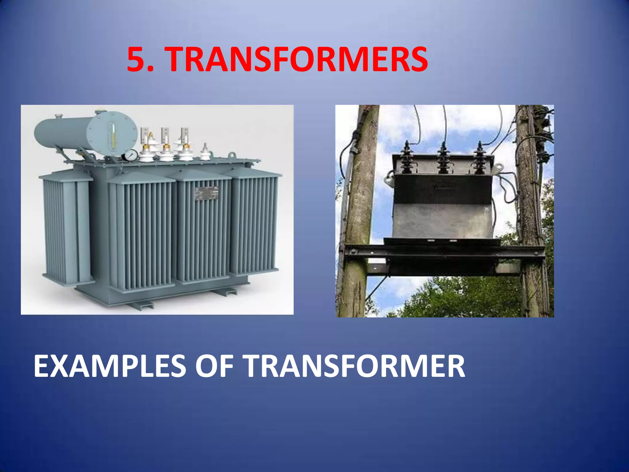
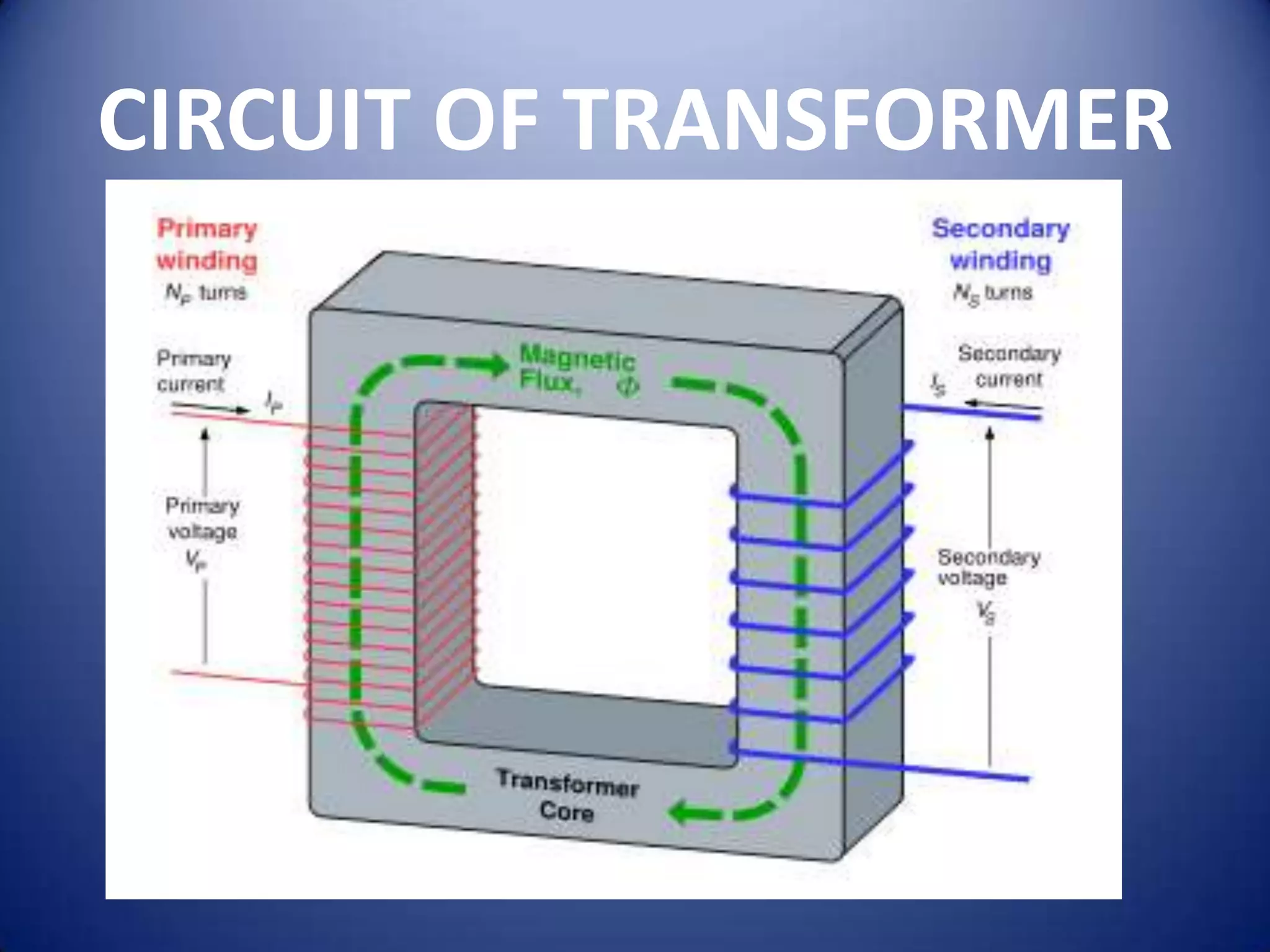
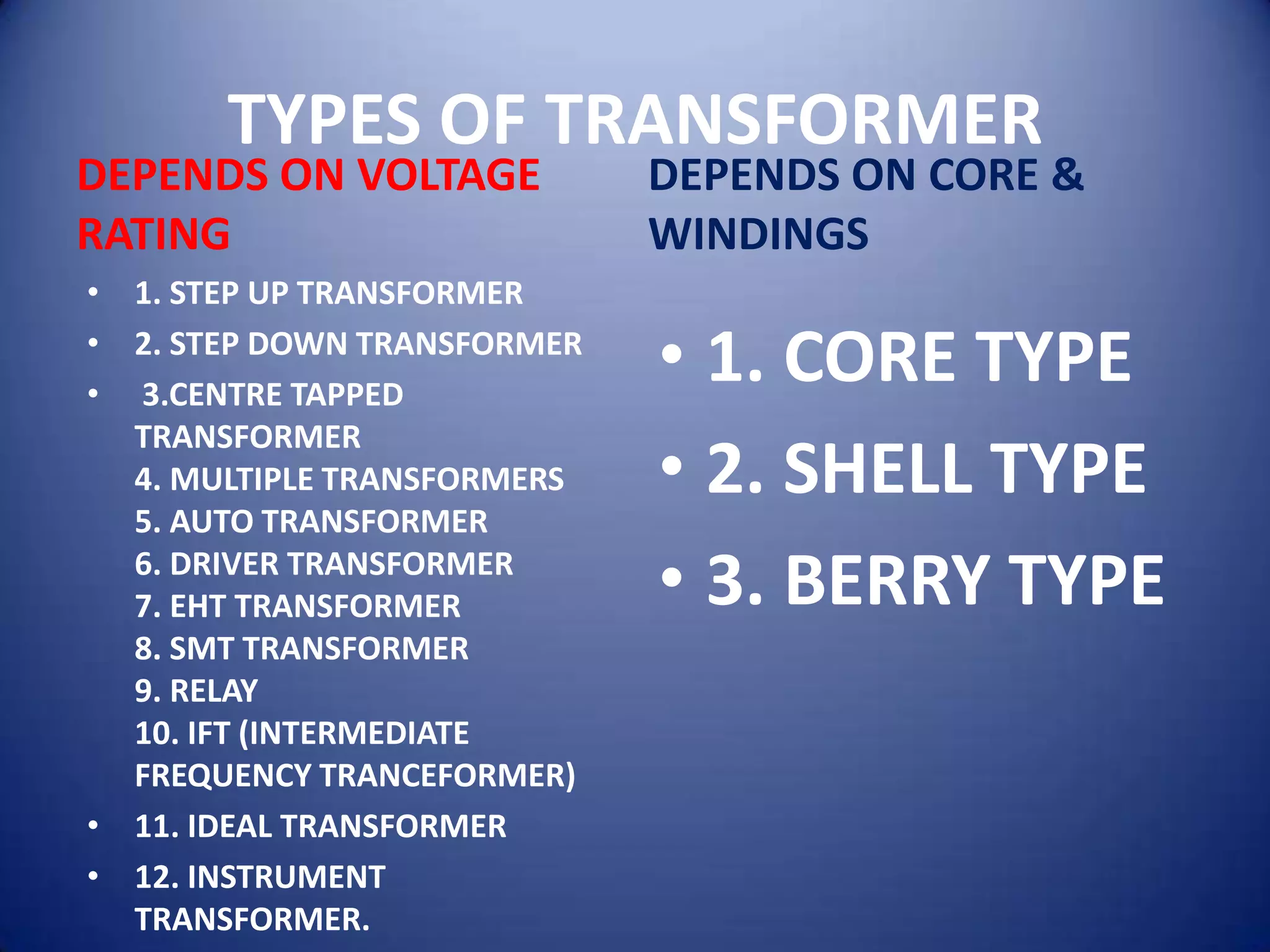

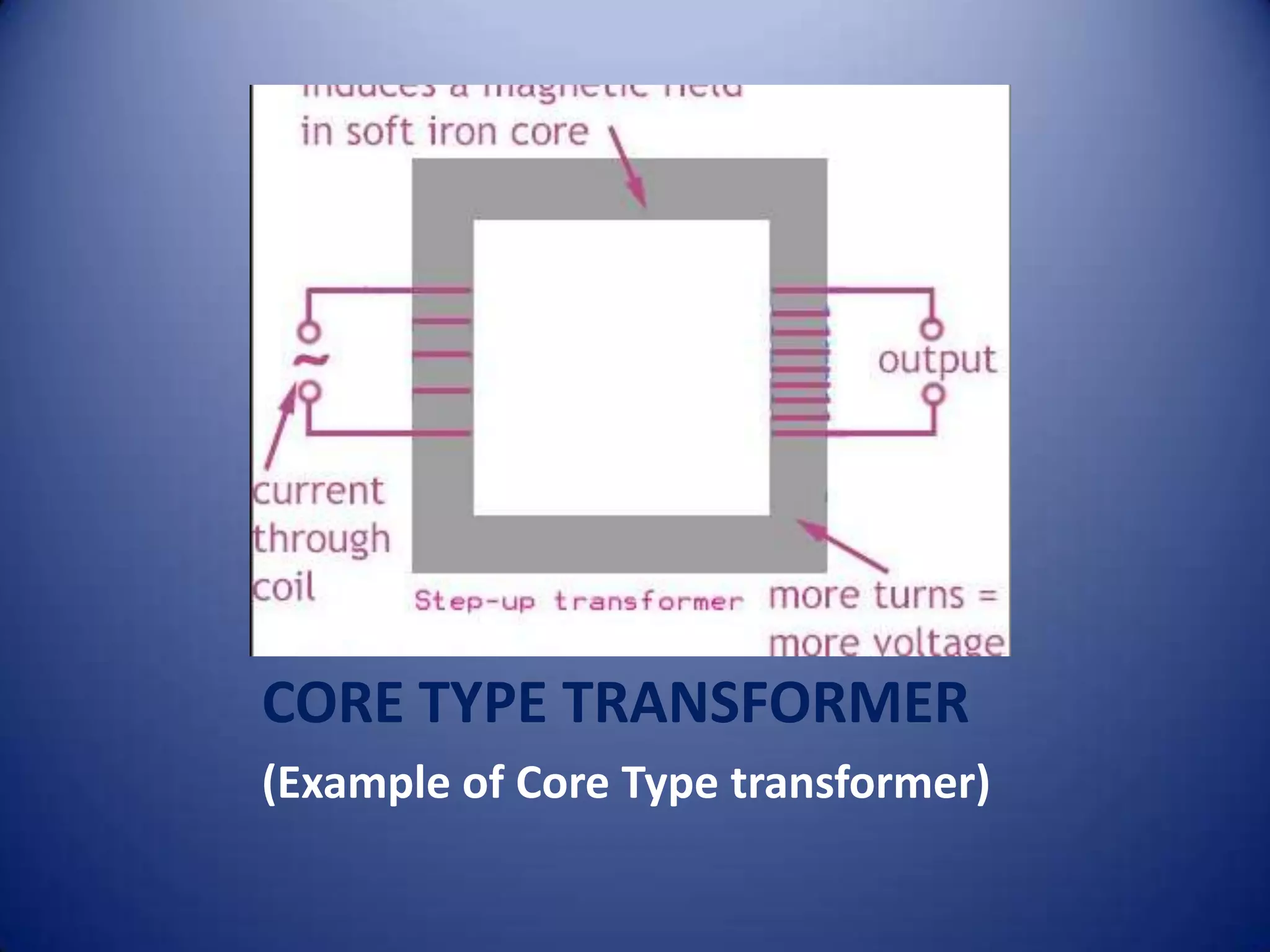
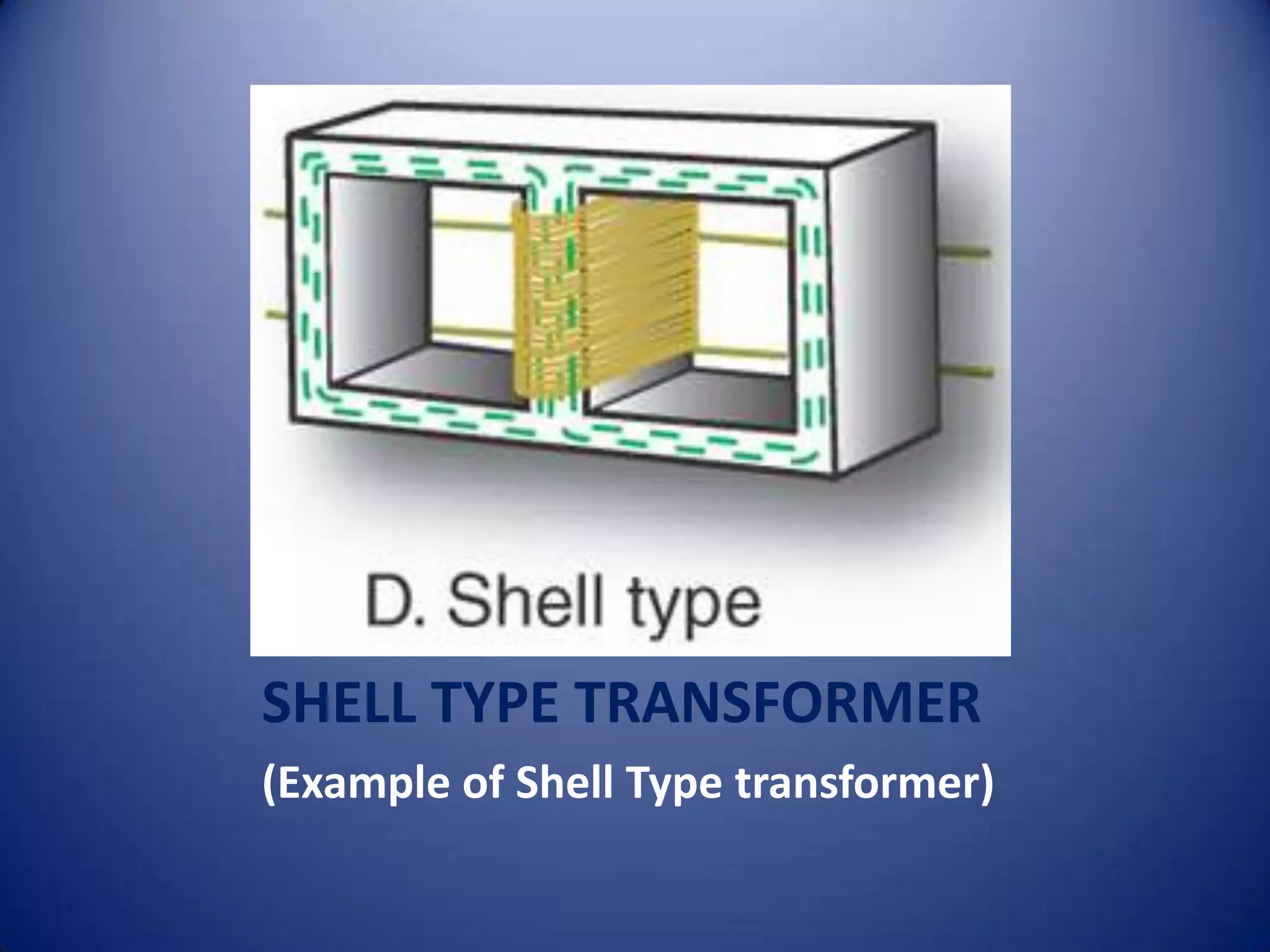
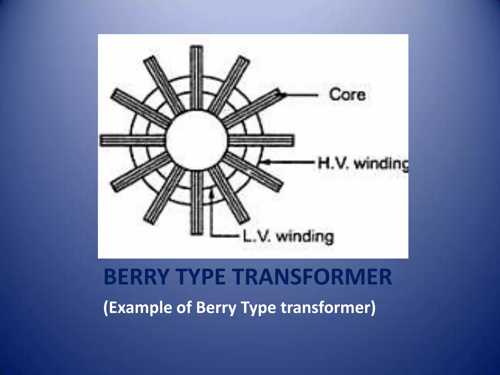
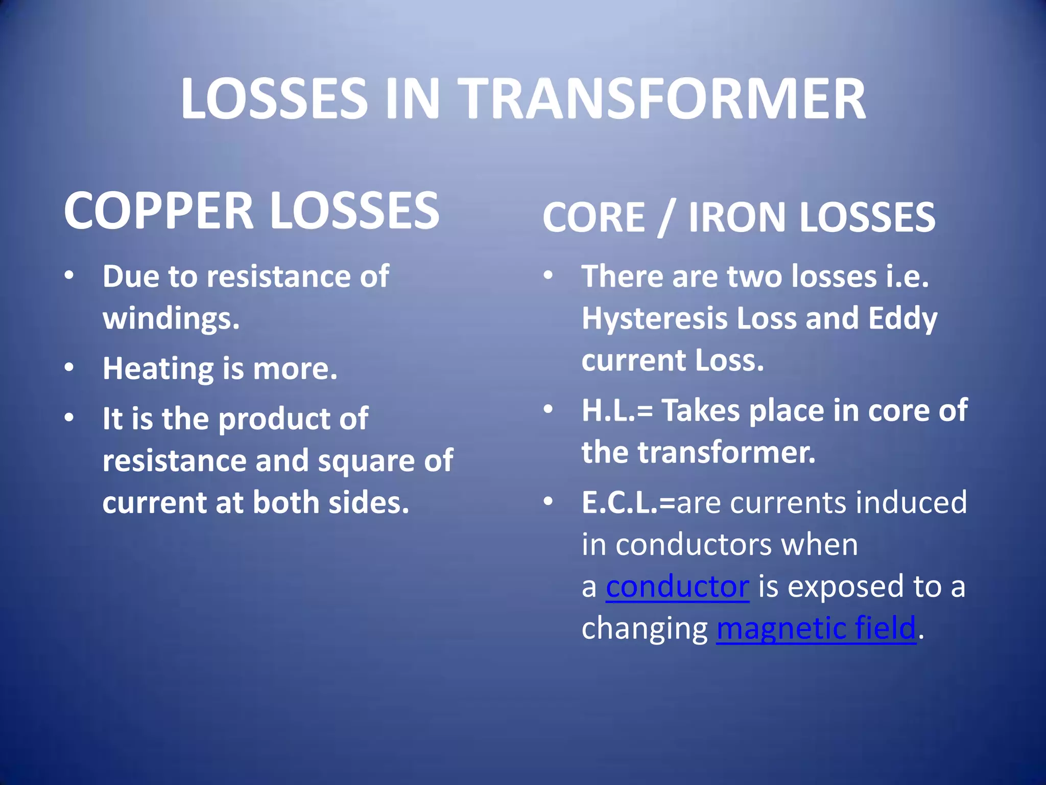
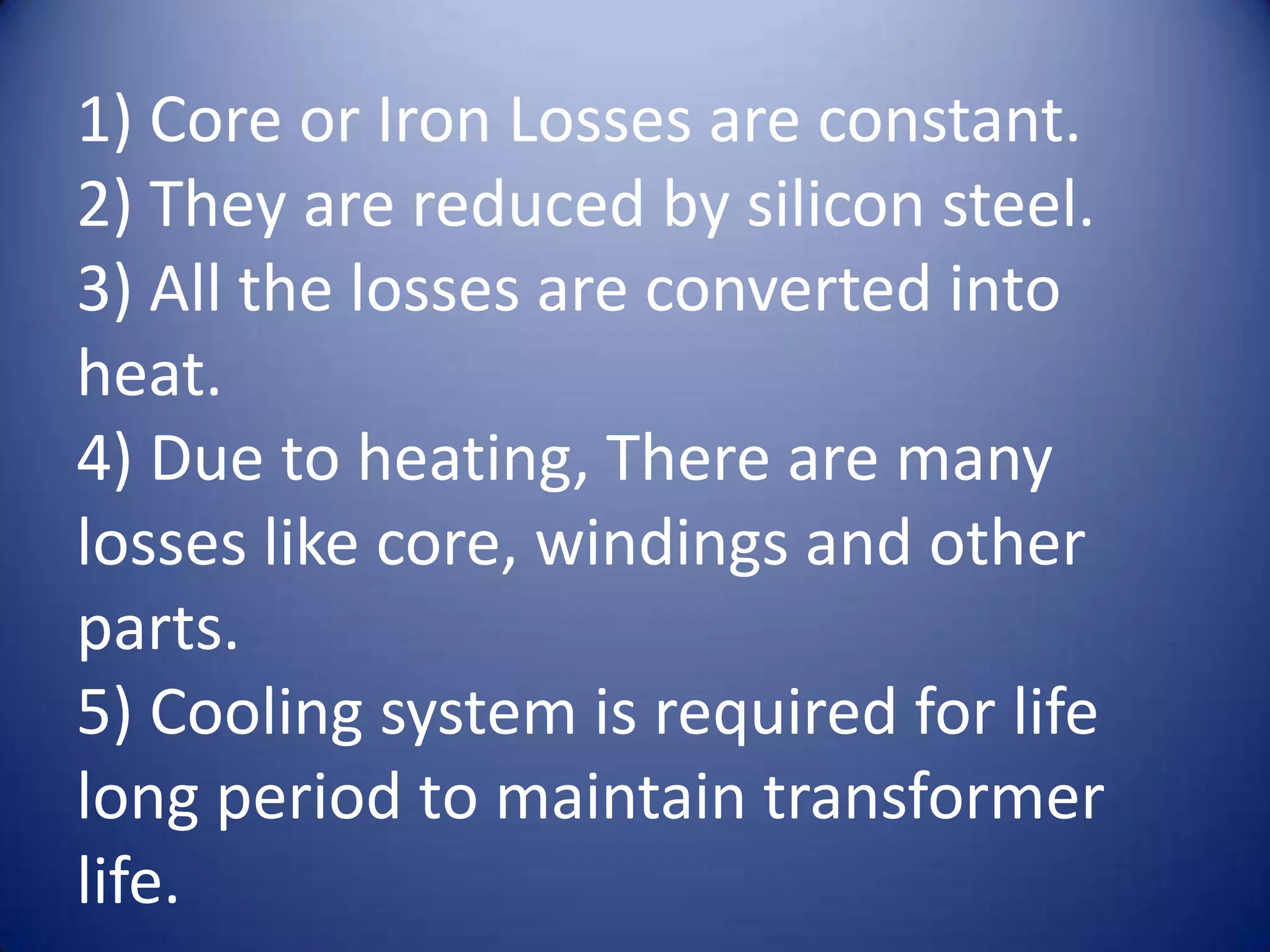
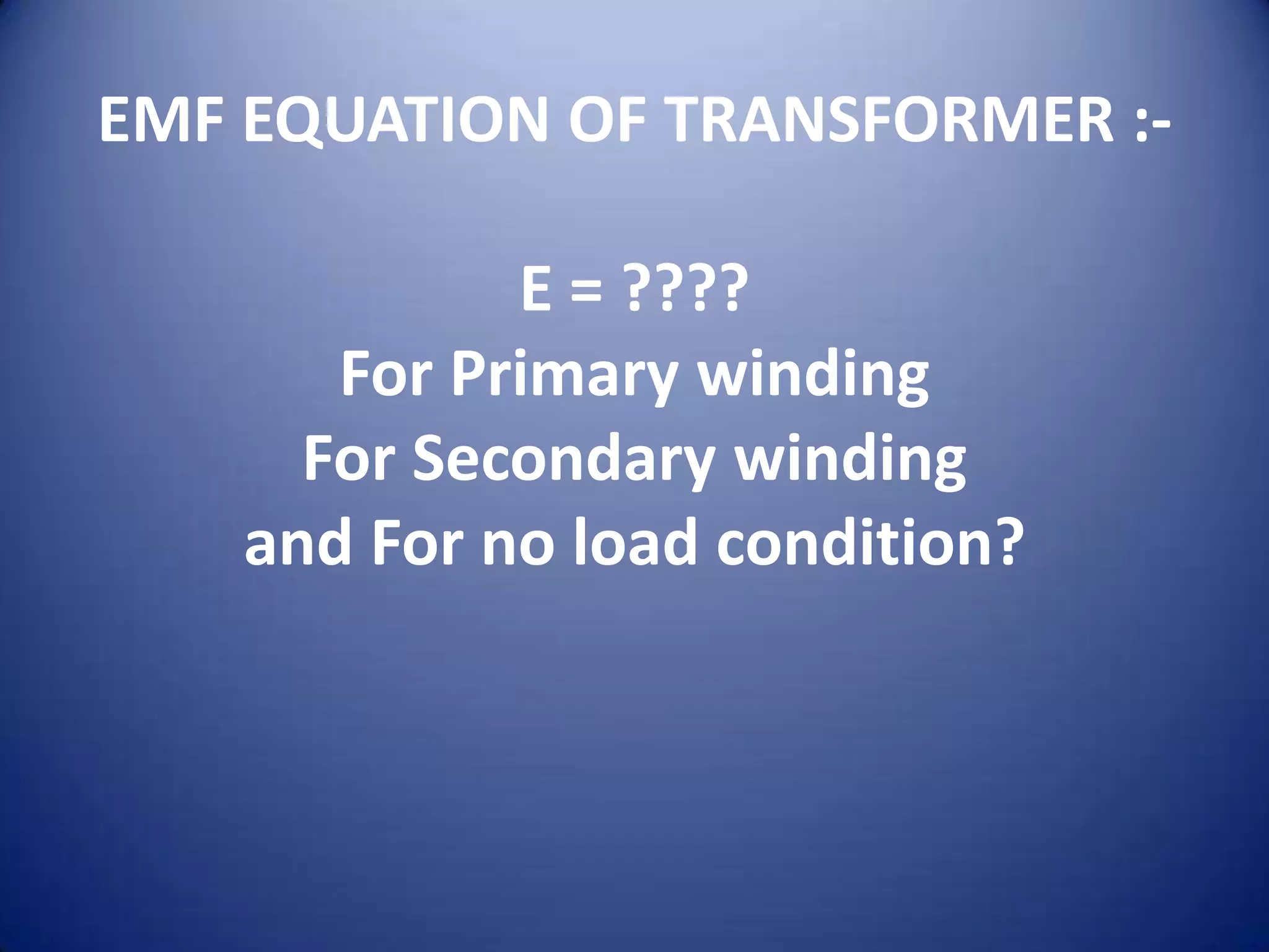


This document provides an overview of electrical transformers. It begins with definitions of different types of transformers, including step up transformers, step down transformers, center tapped transformers, and more. It then provides examples and diagrams of core type, shell type, and berry type transformers. The rest of the document discusses each transformer type in more detail and also covers losses in transformers, the EMF equation, and some example problems.