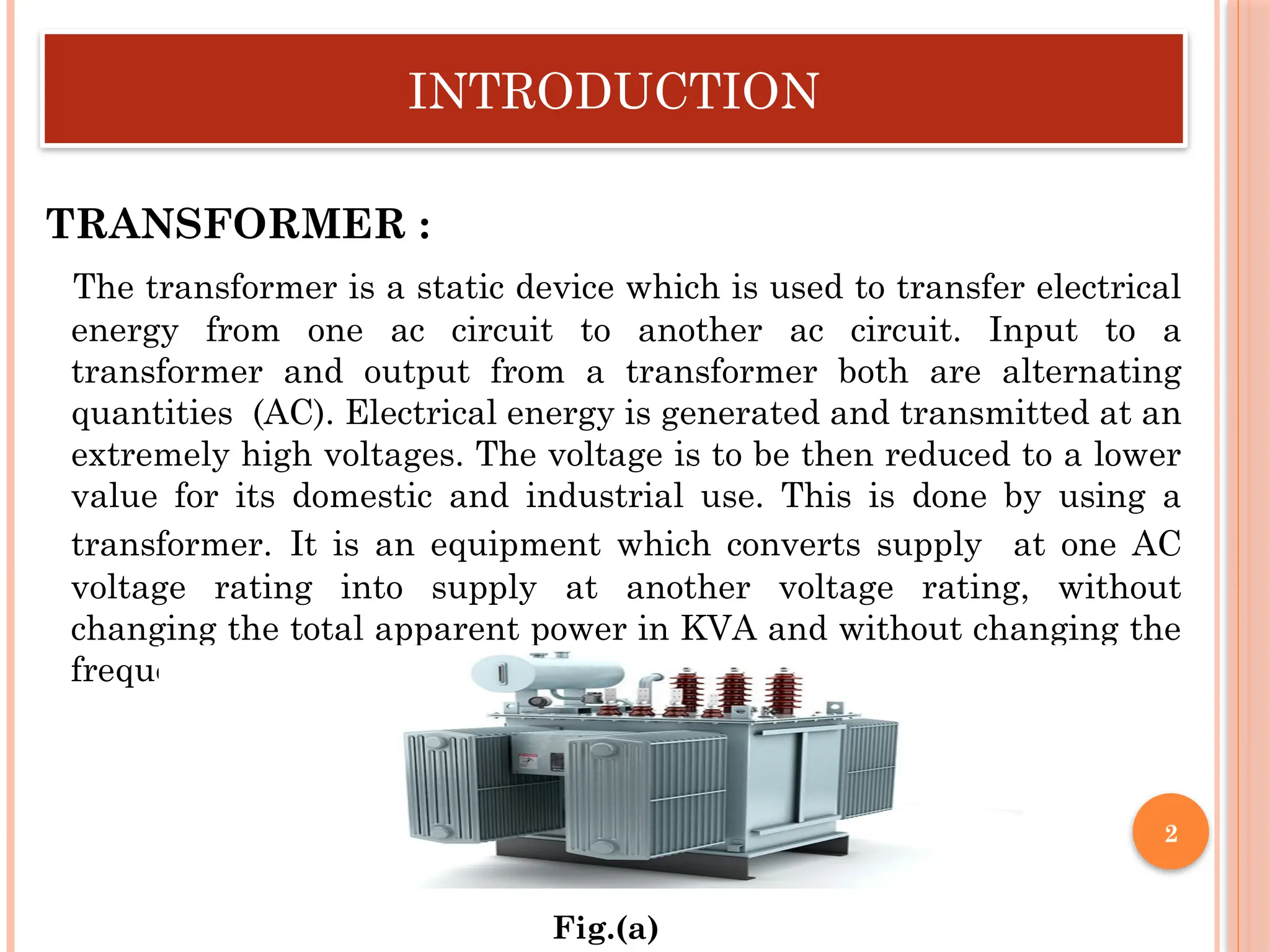
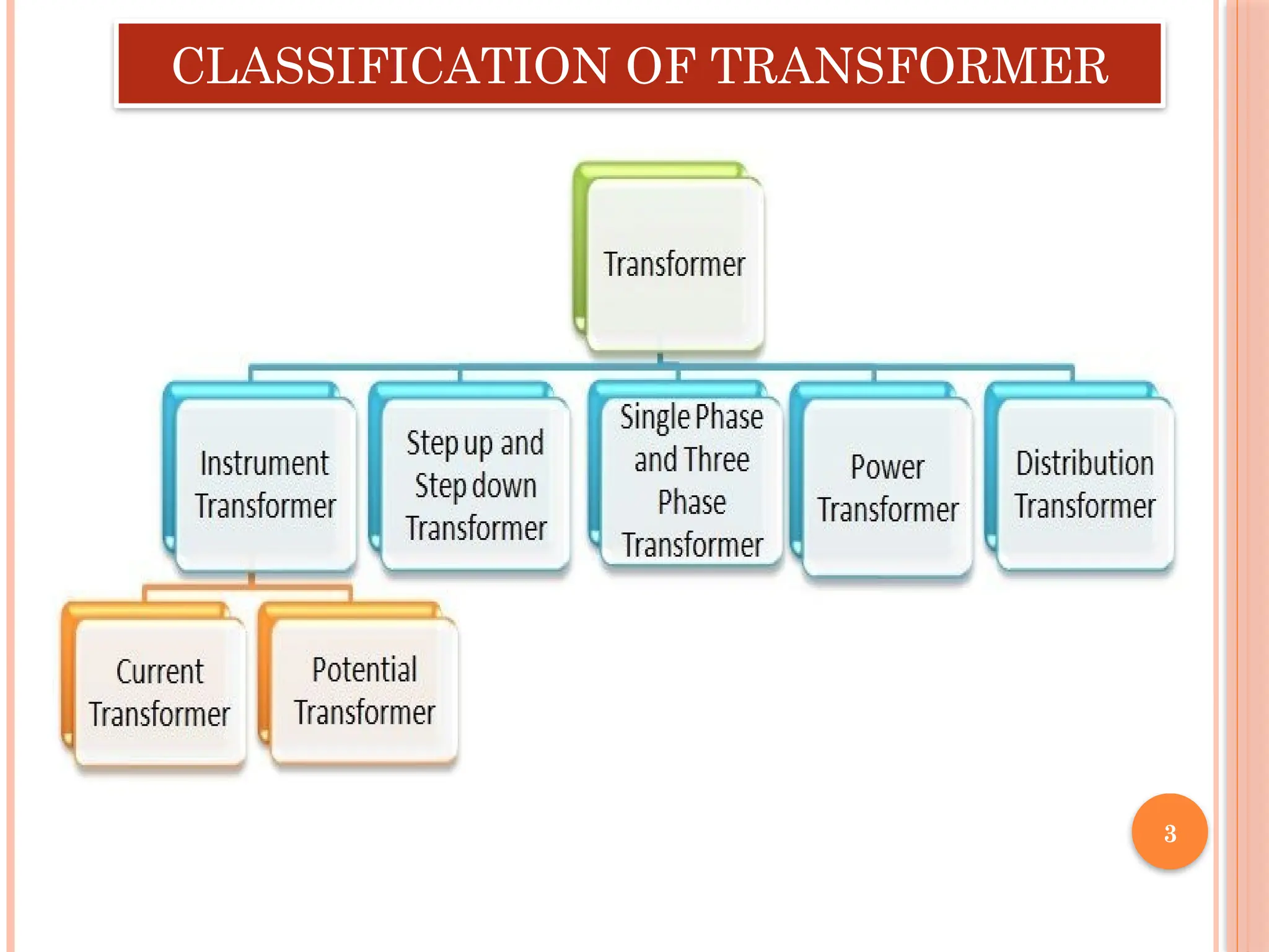
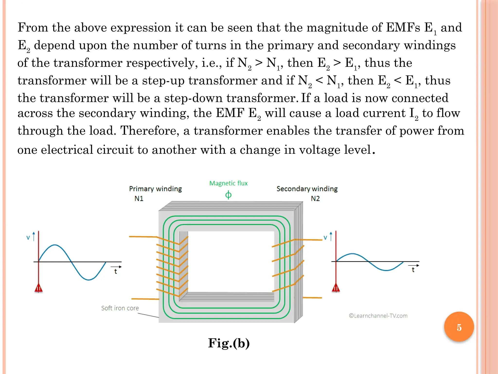
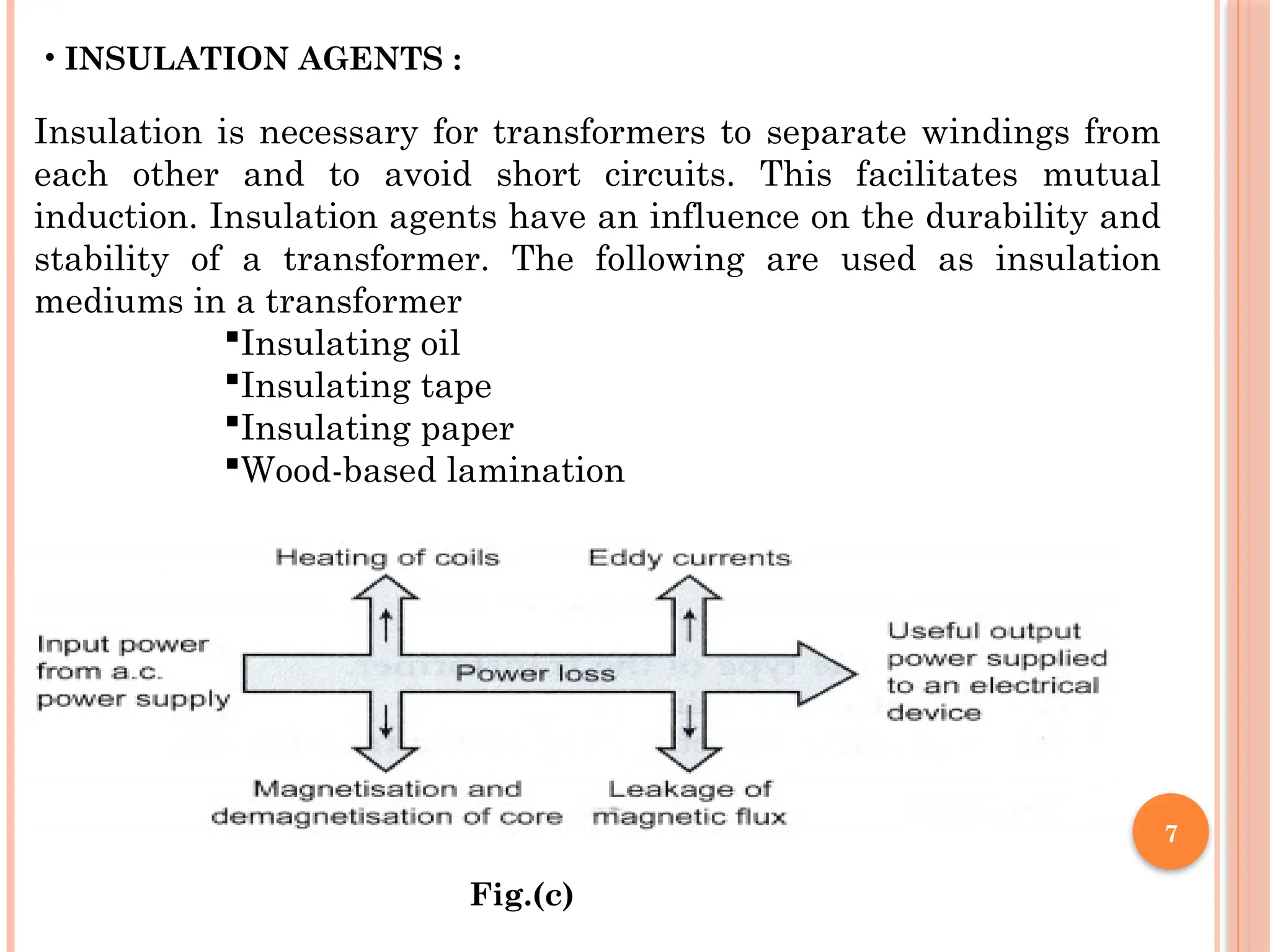
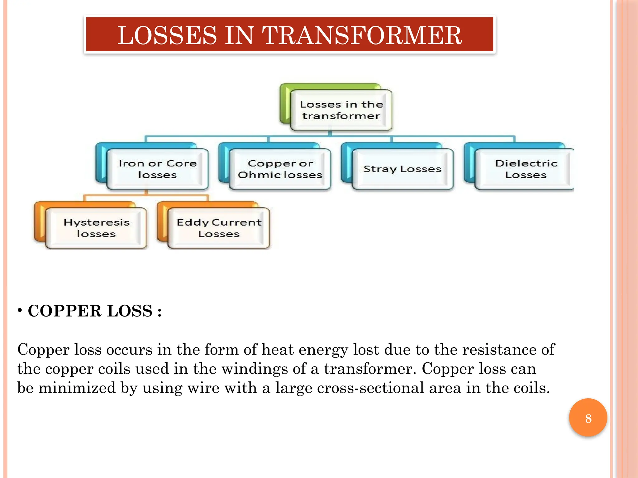
PRESENTATION ON
TRANSFORMER
PREPARED BY:
KRISHNA RAJ GAUTAM
SOUMYA RANJAN MALLICK
PANKAJ GOND
SUBMITTED TO:
KARTHIKEYAN SIR
TABLE OF CONTENT
Introduction
Classification of transformer
Working Principle of transformer
Construction of transformer
Losses in transformer
Application of transformer
Conclusion
1
INTRODUCTION
TRANSFORMER :
The transformer is a static device which is used to transfer electrical
energy from one ac circuit to another ac circuit. Input to a
transformer and output from a transformer both are alternating
quantities (AC). Electrical energy is generated and transmitted at an
extremely high voltages. The voltage is to be then reduced to a lower
value for its domestic and industrial use. This is done by using a
transformer. It is an equipment which converts supply at one AC
voltage rating into supply at another voltage rating, without
changing the total apparent power in KVA and without changing the
frequency of the system.
Fig.(a)
2
CLASSIFICATION OF TRANSFORMER
3
WORKING PRINCIPLE OF TRANSFORMER
The working of the transformer is based on the principle of mutual inductance
between two coils which are magnetic coupled. According to the principle of
mutual inductance, when an alternating voltage is applied to the primary
winding of the transformer, an alternating flux ϕm
which is called as the
mutual flux is produced in the core. This alternating flux links both the
windings magnetically and induces EMFs E1
in the primary winding and E2
in
the secondary winding of the transformer according to Faraday’s law of
electromagnetic induction. The EMF (E1
) is called as primary EMF and the
EMF (E2
) is known as secondary EMF and being given as,
E1=−N1dφm/dt
And
E2=−N2dφm/dt
Therefore,
E2/E1=N2/N1
4
From the above expression it can be seen that the magnitude of EMFs E1
and
E2
depend upon the number of turns in the primary and secondary windings
of the transformer respectively, i.e., if N2
> N1
, then E2
> E1
, thus the
transformer will be a step-up transformer and if N2
< N1
, then E2
< E1
, thus
the transformer will be a step-down transformer. If a load is now connected
across the secondary winding, the EMF E2
will cause a load current I2
to flow
through the load. Therefore, a transformer enables the transfer of power from
one electrical circuit to another with a change in voltage level.
5
Fig.(b)
6
CONSTRUCTION OF
TRANSFORMER
• CORE :
The core acts as a support to the winding in the transformer. It also provides a
low reluctance path to the flow of magnetic flux. The winding is wound on the
core, as shown in the picture. It is made up of a laminated soft iron core in
order to reduce the losses in a transformer. The factors, such as operating
voltage, current, power, etc., decide core composition. The core diameter is
directly proportional to copper losses and inversely proportional to iron losses.
The major parts of single phase transformer are :
• WINDINGS :
Windings are the set of copper wires wound over the transformer core.
Copper wires are used due to the following:
The high conductivity of copper minimises the loss in a transformer
because when the conductivity increases, resistance to current flow
decreases. The high ductility of copper is the property of metals that
allows it to be made into very thin wires. There are mainly two types of
windings: primary windings and secondary windings. Primary winding:
The set of turns of windings to which the supply current is fed.
Secondary winding: The set of turns of winding from which output is
taken.
7
• INSULATION AGENTS :
Insulation is necessary for transformers to separate windings from
each other and to avoid short circuits. This facilitates mutual
induction. Insulation agents have an influence on the durability and
stability of a transformer. The following are used as insulation
mediums in a transformer
Insulating oil
Insulating tape
Insulating paper
Wood-based lamination
Fig.(c)
8
LOSSES IN TRANSFORMER
• COPPER LOSS :
Copper loss occurs in the form of heat energy lost due to the resistance of
the copper coils used in the windings of a transformer. Copper loss can
be minimized by using wire with a large cross-sectional area in the coils.
9
• HYSTERESIS LOSS :
Loss of energy due to continuous magnetization and demagnetization of the
transformer is called hysteresis loss. Hysteresis loss in a transformer can be
minimized by using soft magnetic materials for the core like permalloy or
silicon iron.
• EDDY CURRENT LOSS :
Energy loss in a metallic plate when kept in a time-varying magnetic field
causes eddy current loss. It can be minimized by using a laminated iron core
in the transformer.
• STRAY LOSS :
We all know that a transformer works on a principle of mutual induction wherein the
alternating current in the primary winding produces magnetic flux lines by which emf
is induced in the secondary winding. But in real-time, all the flux produced by the
primary side does not link with the secondary side completely. This is called a flux
leakage and will cause some losses in the transformer reducing the output power.
• DIELECTRIC LOSS :
Dielectric loss occurs in the insulating medium of the transformer. In general, Oil is
used as a dielectric medium.Due to the continuous operation of the transformer, the
strength of the dielectric is reduced. When the quality of the oil deteriorates, it causes
some losses known as Dielectric losses which decrease the overall efficiency of the
transformer.
10
APPLICATION OF TRANSFORMER
• The power transformer is used to increase otherwise decrease voltage
within a power distribution network.
• Distribution transformer is mainly used to decrease a voltage for
distribution to commercial & residential users.
• Instrument transformer is used to decrease high voltage as well as
current and after that, it can be measured & carefully used through
conventional devices.
• Single-phase transformer is frequently used to provide power for
receptacle, residential lighting, AC & heating requirements.
• A three-phase transformer is used to achieve cost-effective power
distribution.
• Autotransformers & Two-winding are normally used to increase or
decrease voltage from the grids like transmission to distribution.
Oil cooled transformers are used in electrical substations or power
distribution.
11
CONCLUSION
A transformer is a passive electrical device that can change the voltage in an
alternating current (AC) electric circuit. Transformers are used to increase or
decrease the operating voltage levels between circuits. A transformer works on
the principle of electromagnetic induction and mutual induction.
Four basic functions are performed in a transformer:
• Mutual induction is present between the two linked circuits
• There is a transfer of electrical energy from one circuit to another
• Electric power gets transferred without showing any change in the frequency
• Electromagnetic induction transfers electrical power
Thank You
12

Presentation on Transformer.pptx and diffrent parts

  • 1.
    PRESENTATION ON TRANSFORMER PREPARED BY: KRISHNARAJ GAUTAM SOUMYA RANJAN MALLICK PANKAJ GOND SUBMITTED TO: KARTHIKEYAN SIR
  • 2.
    TABLE OF CONTENT Introduction Classificationof transformer Working Principle of transformer Construction of transformer Losses in transformer Application of transformer Conclusion 1
  • 3.
    INTRODUCTION TRANSFORMER : The transformeris a static device which is used to transfer electrical energy from one ac circuit to another ac circuit. Input to a transformer and output from a transformer both are alternating quantities (AC). Electrical energy is generated and transmitted at an extremely high voltages. The voltage is to be then reduced to a lower value for its domestic and industrial use. This is done by using a transformer. It is an equipment which converts supply at one AC voltage rating into supply at another voltage rating, without changing the total apparent power in KVA and without changing the frequency of the system. Fig.(a) 2
  • 4.
  • 5.
    WORKING PRINCIPLE OFTRANSFORMER The working of the transformer is based on the principle of mutual inductance between two coils which are magnetic coupled. According to the principle of mutual inductance, when an alternating voltage is applied to the primary winding of the transformer, an alternating flux ϕm which is called as the mutual flux is produced in the core. This alternating flux links both the windings magnetically and induces EMFs E1 in the primary winding and E2 in the secondary winding of the transformer according to Faraday’s law of electromagnetic induction. The EMF (E1 ) is called as primary EMF and the EMF (E2 ) is known as secondary EMF and being given as, E1=−N1dφm/dt And E2=−N2dφm/dt Therefore, E2/E1=N2/N1 4
  • 6.
    From the aboveexpression it can be seen that the magnitude of EMFs E1 and E2 depend upon the number of turns in the primary and secondary windings of the transformer respectively, i.e., if N2 > N1 , then E2 > E1 , thus the transformer will be a step-up transformer and if N2 < N1 , then E2 < E1 , thus the transformer will be a step-down transformer. If a load is now connected across the secondary winding, the EMF E2 will cause a load current I2 to flow through the load. Therefore, a transformer enables the transfer of power from one electrical circuit to another with a change in voltage level. 5 Fig.(b)
  • 7.
    6 CONSTRUCTION OF TRANSFORMER • CORE: The core acts as a support to the winding in the transformer. It also provides a low reluctance path to the flow of magnetic flux. The winding is wound on the core, as shown in the picture. It is made up of a laminated soft iron core in order to reduce the losses in a transformer. The factors, such as operating voltage, current, power, etc., decide core composition. The core diameter is directly proportional to copper losses and inversely proportional to iron losses. The major parts of single phase transformer are : • WINDINGS : Windings are the set of copper wires wound over the transformer core. Copper wires are used due to the following: The high conductivity of copper minimises the loss in a transformer because when the conductivity increases, resistance to current flow decreases. The high ductility of copper is the property of metals that allows it to be made into very thin wires. There are mainly two types of windings: primary windings and secondary windings. Primary winding: The set of turns of windings to which the supply current is fed. Secondary winding: The set of turns of winding from which output is taken.
  • 8.
    7 • INSULATION AGENTS: Insulation is necessary for transformers to separate windings from each other and to avoid short circuits. This facilitates mutual induction. Insulation agents have an influence on the durability and stability of a transformer. The following are used as insulation mediums in a transformer Insulating oil Insulating tape Insulating paper Wood-based lamination Fig.(c)
  • 9.
    8 LOSSES IN TRANSFORMER •COPPER LOSS : Copper loss occurs in the form of heat energy lost due to the resistance of the copper coils used in the windings of a transformer. Copper loss can be minimized by using wire with a large cross-sectional area in the coils.
  • 10.
    9 • HYSTERESIS LOSS: Loss of energy due to continuous magnetization and demagnetization of the transformer is called hysteresis loss. Hysteresis loss in a transformer can be minimized by using soft magnetic materials for the core like permalloy or silicon iron. • EDDY CURRENT LOSS : Energy loss in a metallic plate when kept in a time-varying magnetic field causes eddy current loss. It can be minimized by using a laminated iron core in the transformer. • STRAY LOSS : We all know that a transformer works on a principle of mutual induction wherein the alternating current in the primary winding produces magnetic flux lines by which emf is induced in the secondary winding. But in real-time, all the flux produced by the primary side does not link with the secondary side completely. This is called a flux leakage and will cause some losses in the transformer reducing the output power. • DIELECTRIC LOSS : Dielectric loss occurs in the insulating medium of the transformer. In general, Oil is used as a dielectric medium.Due to the continuous operation of the transformer, the strength of the dielectric is reduced. When the quality of the oil deteriorates, it causes some losses known as Dielectric losses which decrease the overall efficiency of the transformer.
  • 11.
    10 APPLICATION OF TRANSFORMER •The power transformer is used to increase otherwise decrease voltage within a power distribution network. • Distribution transformer is mainly used to decrease a voltage for distribution to commercial & residential users. • Instrument transformer is used to decrease high voltage as well as current and after that, it can be measured & carefully used through conventional devices. • Single-phase transformer is frequently used to provide power for receptacle, residential lighting, AC & heating requirements. • A three-phase transformer is used to achieve cost-effective power distribution. • Autotransformers & Two-winding are normally used to increase or decrease voltage from the grids like transmission to distribution. Oil cooled transformers are used in electrical substations or power distribution.
  • 12.
    11 CONCLUSION A transformer isa passive electrical device that can change the voltage in an alternating current (AC) electric circuit. Transformers are used to increase or decrease the operating voltage levels between circuits. A transformer works on the principle of electromagnetic induction and mutual induction. Four basic functions are performed in a transformer: • Mutual induction is present between the two linked circuits • There is a transfer of electrical energy from one circuit to another • Electric power gets transferred without showing any change in the frequency • Electromagnetic induction transfers electrical power
  • 13.