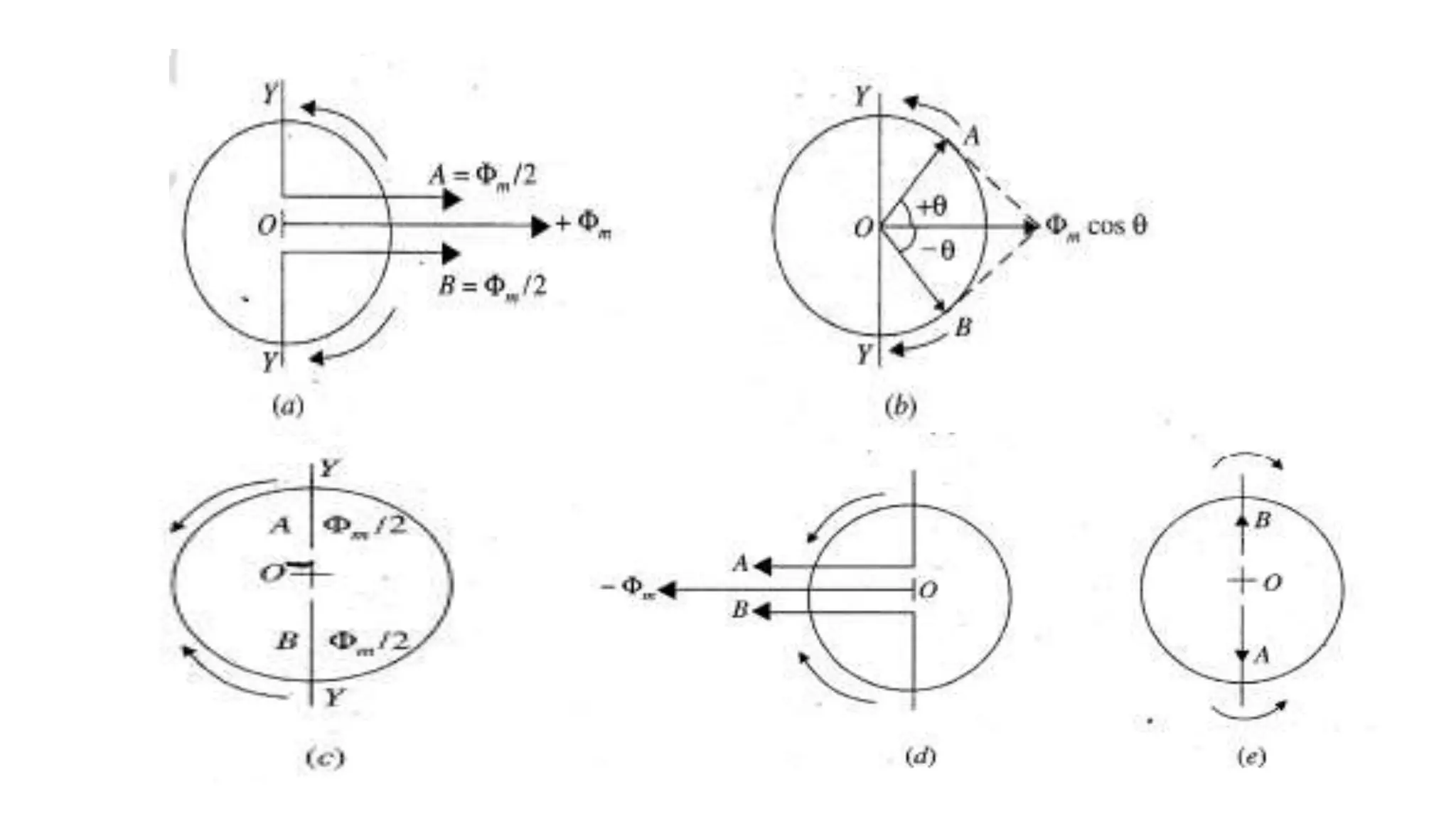
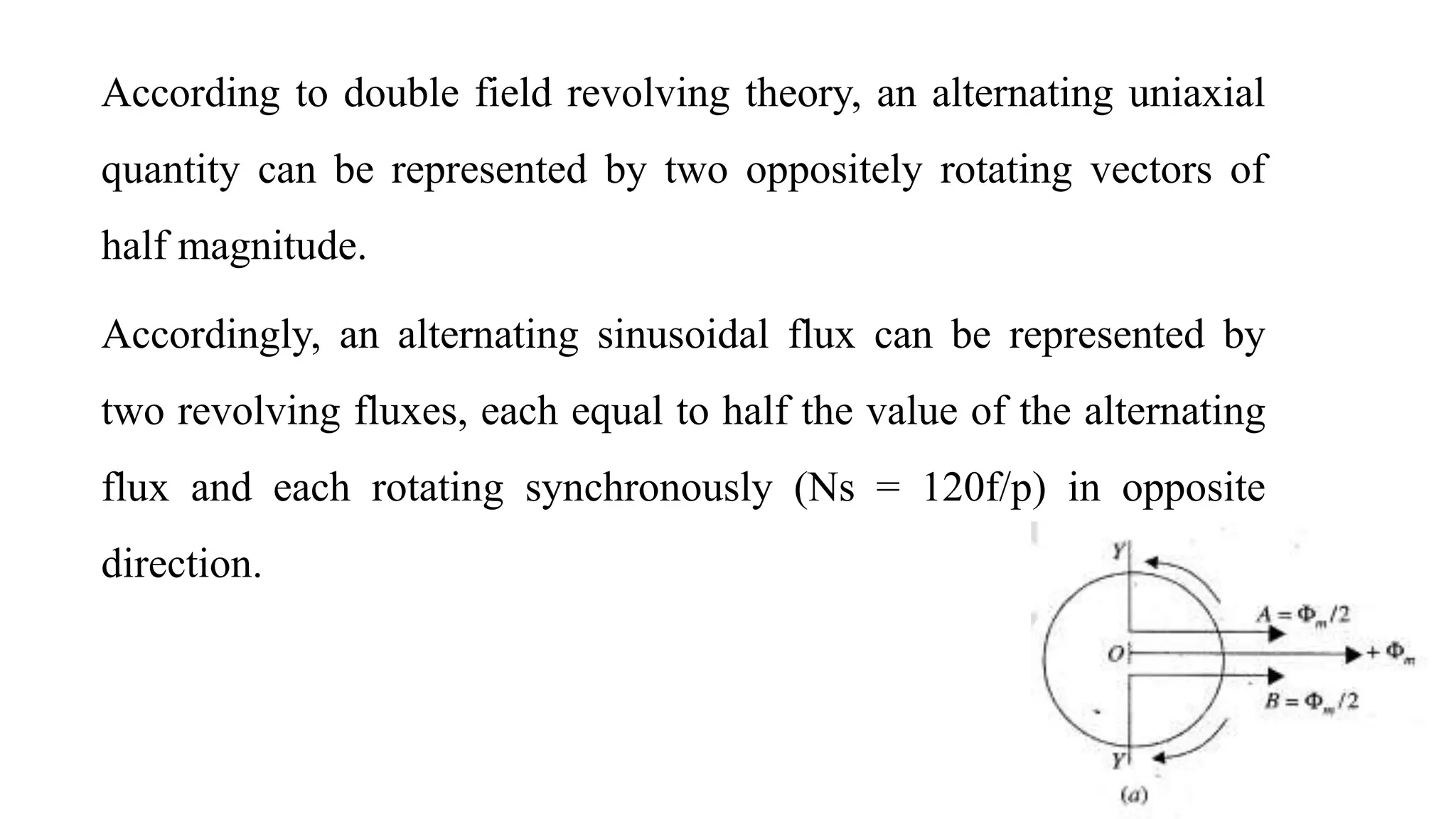
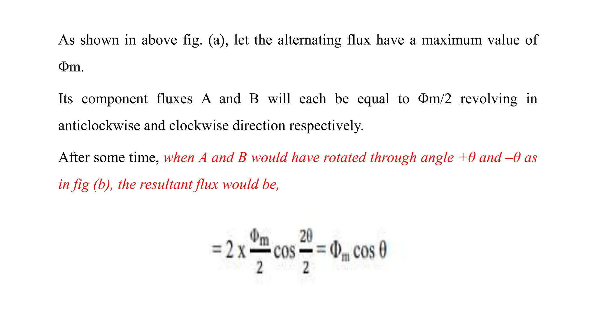
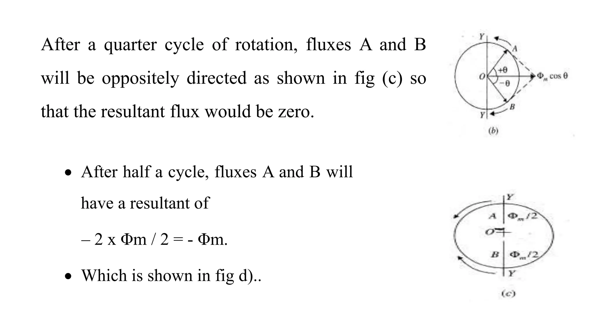
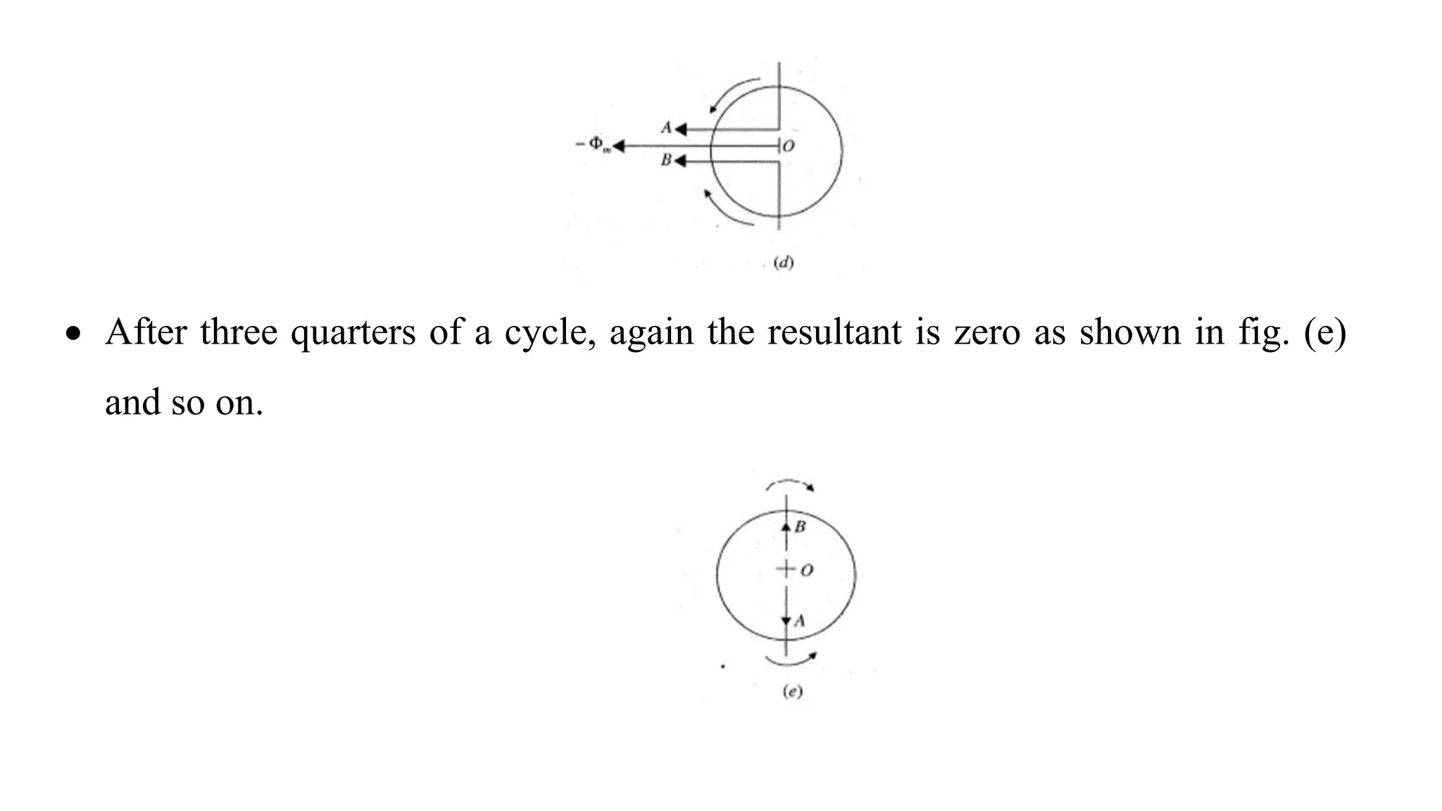
Single-phase induction motors
• Constructional features, double revolving field theory,
• Equivalent circuit, determination of parameters.
• Split-phase starting methods and applications.
Double Revolving field theory
Introduction
If, however, the rotor is in motion in any direction when supply for the stator is
switched on, it can be shown that the rotor develops more torque in that
direction.
The net torque then, would have non-zero value, and under its impact the rotor
would speed up in its direction.
The analysis of the single phase motor can be made on the basis of two theories:
i. Double revolving field theory, and
ii.ii. Cross field theory.
Double revolving field theory –
Double Revolving Field Theory, states that a single pulsating
magnetic field of as its maximum value can be resolved into
two rotating magnetic fields of (m/2) as their magnitude
rotating in opposite directions at synchronous speed
proportional to the frequency of the pulsating magnetic field.
According to double field revolving theory, an alternating uniaxial
quantity can be represented by two oppositely rotating vectors of
half magnitude.
Accordingly, an alternating sinusoidal flux can be represented by
two revolving fluxes, each equal to half the value of the alternating
flux and each rotating synchronously (Ns = 120f/p) in opposite
direction.
As shown in above fig. (a), let the alternating flux have a maximum value of
Φm.
Its component fluxes A and B will each be equal to Φm/2 revolving in
anticlockwise and clockwise direction respectively.
After some time, when A and B would have rotated through angle +θ and –θ as
in fig (b), the resultant flux would be,
After a quarter cycle of rotation, fluxes A and B
will be oppositely directed as shown in fig (c) so
that the resultant flux would be zero.
 After half a cycle, fluxes A and B will
have a resultant of
– 2 x Φm / 2 = - Φm.
 Which is shown in fig d)..
 After three quarters of a cycle, again the resultant is zero as shown in fig. (e)
and so on.
If we plot the resultant flux against θ between θ = 0° and 360°, an
alternating flux is obtained.
That is why alternating flux is considered to have two fluxes, each
half the value and revolving synchronously in opposite directions.

Double Revolving field theory-how the rotor develops torque

  • 1.
    Single-phase induction motors •Constructional features, double revolving field theory, • Equivalent circuit, determination of parameters. • Split-phase starting methods and applications.
  • 2.
    Double Revolving fieldtheory Introduction If, however, the rotor is in motion in any direction when supply for the stator is switched on, it can be shown that the rotor develops more torque in that direction. The net torque then, would have non-zero value, and under its impact the rotor would speed up in its direction. The analysis of the single phase motor can be made on the basis of two theories: i. Double revolving field theory, and ii.ii. Cross field theory.
  • 4.
    Double revolving fieldtheory – Double Revolving Field Theory, states that a single pulsating magnetic field of as its maximum value can be resolved into two rotating magnetic fields of (m/2) as their magnitude rotating in opposite directions at synchronous speed proportional to the frequency of the pulsating magnetic field.
  • 5.
    According to doublefield revolving theory, an alternating uniaxial quantity can be represented by two oppositely rotating vectors of half magnitude. Accordingly, an alternating sinusoidal flux can be represented by two revolving fluxes, each equal to half the value of the alternating flux and each rotating synchronously (Ns = 120f/p) in opposite direction.
  • 6.
    As shown inabove fig. (a), let the alternating flux have a maximum value of Φm. Its component fluxes A and B will each be equal to Φm/2 revolving in anticlockwise and clockwise direction respectively. After some time, when A and B would have rotated through angle +θ and –θ as in fig (b), the resultant flux would be,
  • 7.
    After a quartercycle of rotation, fluxes A and B will be oppositely directed as shown in fig (c) so that the resultant flux would be zero.  After half a cycle, fluxes A and B will have a resultant of – 2 x Φm / 2 = - Φm.  Which is shown in fig d)..
  • 8.
     After threequarters of a cycle, again the resultant is zero as shown in fig. (e) and so on.
  • 9.
    If we plotthe resultant flux against θ between θ = 0° and 360°, an alternating flux is obtained. That is why alternating flux is considered to have two fluxes, each half the value and revolving synchronously in opposite directions.