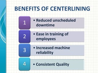
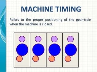
MACHINE TIMING
AND REGISTRATION
    STRIVING FOR CONSISTENCY
           IN THE CONVERSION
                     PROCESS
CONVERTING
CENTERLINING
  (QUICK OVERVIEW)
BENEFITS OF CENTERLINING
      • Reduced unscheduled
  1     downtime

      • Ease in training of
  2     employees

      • Increased machine
  3     reliability

  4   • Consistent Quality
CONVERTING
      CENTERLINING
       Why is it Important?

Centerlining allows us to control the steps and
actions within the manufacturing process. The
result is a quality product that meets our
customers’ quality requirements from crew to
crew and from run to run.
THE CONVERTING
CENTERLINING PROCESS
Converting Centerlining is a systematic method of
increasing throughput and decreasing variability in
the conversion process.

There are 2 Sections of the Converting Centerlining
Process:
   • Nip Point Calibration
   • Machine Timing and Registration
NIP POINT
CALIBRATION
BENEFITS OF NIP POINT
    CALIBRATION

1   • Reduce Set-Up Errors

    • Removes Variation in the
2     Converting Process

    • Reduces Cross Training
3     Requirements
NIP POINT CALIBRATION
      Why is it Important?

Ensures the actual distance between
components perfectly match the indicators
and gauges on the converting machine
NIP POINT CALIBRATION
Nip Point Calibration is a series of SPIs
that address critical sheet control points:
  – SPI-N801 Feed Section Calibration
  – SPI-N802 Print Section Calibration
  – SPI-N803 Anilox Roll Parallel and Calibration
  – SPI-N804 Creaser Slotter Section Calibration
  – SPI-N805 Die cut Section Calibration
  – SPI-N807 Folding Rail Calibration
TIMING &
REGISTRATION
BENEFITS OF TIMING &
   REGISTRATION
1   • Decrease Set-Up Times


2   • Reduce Set-Up Errors


3   • Minimize Waste
TIMING AND
      REGISTRATION
         What is timing?
Machine timing is the relationship
between the position of machine section
gears and the feed section.
MACHINE TIMING
Refers to the proper positioning of the gear-train
when the machine is closed.
MACHINE TIMING
• Crew’s lack of discipline to maintain timing is
  a common failure of centerlining.

• Timing marks should be clear.

• Machines must be maintained in a timed
  state.
MACHINE TIMING
• Different machines may have different timing marks
  and procedures.

• Some machines will have external timing reference
  marks on the outside of the machine that line up with a
  pointer or a scribed position.

• Some machines have internal timing marks or marks on
  the gear itself which must be aligned before exiting the
  machine after a set-up.

• Here are some examples of timing marks:
EXTERNAL TIMING MARKS
United Die Cutter
 The black dial is the timing indicator and 12 o’clock is the timed
 position.


  Register ring: Does not
  Move when the machine
        Is running.

                                          Timing Indicator: turns at a 1:1 ratio with the gear
                                                        Inside the machine.
EXTERNAL TIMING MARKS
     United Die Cutter
Black dial is clear but no real clear timing reference point.
EXTERNAL TIMING MARKS
Ward Die Cutter (Bullet Registers)
Ward Die Cutter timing ring lined up with the timing
reference point.


              Timing Ring
TIMING SUMMARY
• All crews must maintain their machines in a timed
  state!!!
• Timing marks will vary for different machines.
• Timing marks need to be clear.
• Timing is the first hurdle in establishing a centerlined
and one box capable machine.
• Failure to maintain timing is the most common cause
for not being able to reduce set-up waste.
QUESTIONS?

Training

  • 1.
    MACHINE TIMING AND REGISTRATION STRIVING FOR CONSISTENCY IN THE CONVERSION PROCESS
  • 2.
  • 3.
    BENEFITS OF CENTERLINING • Reduced unscheduled 1 downtime • Ease in training of 2 employees • Increased machine 3 reliability 4 • Consistent Quality
  • 4.
    CONVERTING CENTERLINING Why is it Important? Centerlining allows us to control the steps and actions within the manufacturing process. The result is a quality product that meets our customers’ quality requirements from crew to crew and from run to run.
  • 5.
    THE CONVERTING CENTERLINING PROCESS ConvertingCenterlining is a systematic method of increasing throughput and decreasing variability in the conversion process. There are 2 Sections of the Converting Centerlining Process: • Nip Point Calibration • Machine Timing and Registration
  • 6.
  • 7.
    BENEFITS OF NIPPOINT CALIBRATION 1 • Reduce Set-Up Errors • Removes Variation in the 2 Converting Process • Reduces Cross Training 3 Requirements
  • 8.
    NIP POINT CALIBRATION Why is it Important? Ensures the actual distance between components perfectly match the indicators and gauges on the converting machine
  • 9.
    NIP POINT CALIBRATION NipPoint Calibration is a series of SPIs that address critical sheet control points: – SPI-N801 Feed Section Calibration – SPI-N802 Print Section Calibration – SPI-N803 Anilox Roll Parallel and Calibration – SPI-N804 Creaser Slotter Section Calibration – SPI-N805 Die cut Section Calibration – SPI-N807 Folding Rail Calibration
  • 10.
  • 11.
    BENEFITS OF TIMING& REGISTRATION 1 • Decrease Set-Up Times 2 • Reduce Set-Up Errors 3 • Minimize Waste
  • 12.
    TIMING AND REGISTRATION What is timing? Machine timing is the relationship between the position of machine section gears and the feed section.
  • 13.
    MACHINE TIMING Refers tothe proper positioning of the gear-train when the machine is closed.
  • 14.
    MACHINE TIMING • Crew’slack of discipline to maintain timing is a common failure of centerlining. • Timing marks should be clear. • Machines must be maintained in a timed state.
  • 15.
    MACHINE TIMING • Differentmachines may have different timing marks and procedures. • Some machines will have external timing reference marks on the outside of the machine that line up with a pointer or a scribed position. • Some machines have internal timing marks or marks on the gear itself which must be aligned before exiting the machine after a set-up. • Here are some examples of timing marks:
  • 16.
    EXTERNAL TIMING MARKS UnitedDie Cutter The black dial is the timing indicator and 12 o’clock is the timed position. Register ring: Does not Move when the machine Is running. Timing Indicator: turns at a 1:1 ratio with the gear Inside the machine.
  • 17.
    EXTERNAL TIMING MARKS United Die Cutter Black dial is clear but no real clear timing reference point.
  • 18.
    EXTERNAL TIMING MARKS WardDie Cutter (Bullet Registers) Ward Die Cutter timing ring lined up with the timing reference point. Timing Ring
  • 19.
    TIMING SUMMARY • Allcrews must maintain their machines in a timed state!!! • Timing marks will vary for different machines. • Timing marks need to be clear. • Timing is the first hurdle in establishing a centerlined and one box capable machine. • Failure to maintain timing is the most common cause for not being able to reduce set-up waste.
  • 20.

Editor's Notes

  • #2 This template can be used as a starter file for presenting training materials in a group setting.SectionsRight-click on a slide to add sections. Sections can help to organize your slides or facilitate collaboration between multiple authors.NotesUse the Notes section for delivery notes or to provide additional details for the audience. View these notes in Presentation View during your presentation. Keep in mind the font size (important for accessibility, visibility, videotaping, and online production)Coordinated colors Pay particular attention to the graphs, charts, and text boxes. Consider that attendees will print in black and white or grayscale. Run a test print to make sure your colors work when printed in pure black and white and grayscale.Graphics, tables, and graphsKeep it simple: If possible, use consistent, non-distracting styles and colors.Label all graphs and tables.
  • #4 This is another option for an Overview slide.
  • #8 This is another option for an Overview slide.
  • #12 This is another option for an Overview slide.