Download as PDF, PPTX
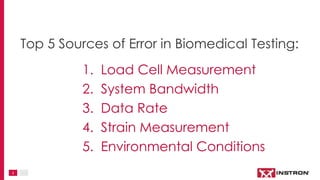

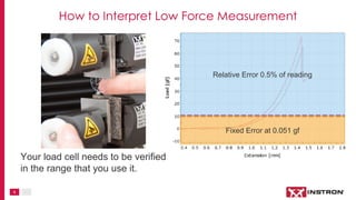
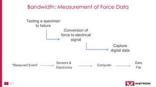
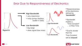
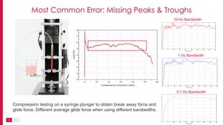
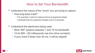
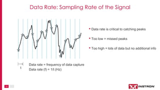
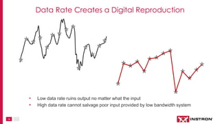
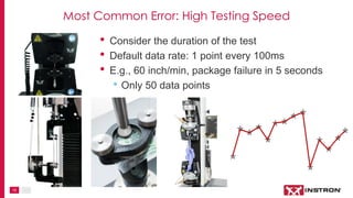

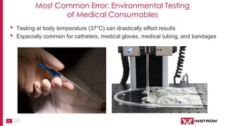
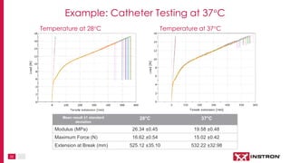

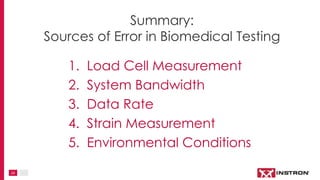


The document outlines the top five sources of error in biomedical testing, including load cell measurement, system bandwidth, data rate, strain measurement, and environmental conditions. It emphasizes the importance of understanding the accuracy and resolution of load cells, the impact of bandwidth on signal clarity, and the significance of appropriate data rates for capturing peak forces. Additionally, it highlights common errors associated with environmental testing conditions and their effects on biomedical device performance.