The document discusses the development of the BarelangFC humanoid robot, designed for the Kontes Robot Indonesia competition, focusing on real-time object detection and coordination using the Tiny-YOLO deep learning method and ZED camera. It describes the robot's capability to detect team members and estimate distances to facilitate accurate ball passing by employing a trigonometric approach for position estimation. Experimental results indicate successful real-time detection and coordination of the robot during tasks.
![International Journal of Electrical and Computer Engineering (IJECE)
Vol. 13, No. 6, December 2023, pp. 6926~6939
ISSN: 2088-8708, DOI: 10.11591/ijece.v13i6.pp6926-6939 6926
Journal homepage: http://ijece.iaescore.com
Tiny-YOLO distance measurement and object detection
coordination system for the BarelangFC robot
Susanto, Jony Arif Ricardo Silitonga, Riska Analia, Eko Rudiawan Jamzuri, Daniel Sutopo Pamungkas
Department of Electrical Engineering, Politeknik Negeri Batam, Batam, Indonesia
Article Info ABSTRACT
Article history:
Received Mar 3, 2023
Revised May 23, 2023
Accepted Jun 4, 2023
A humanoid robot called BarelangFC was designed to take part in the
Kontes Robot Indonesia (KRI) competition, in the robot coordination
division. In this division, each robot is expected to recognize its opponents
and to pass the ball towards a team member to establish coordination
between the robots. In order to achieve this team coordination, a fast and
accurate system is needed to detect and estimate the other robot’s position in
real time. Moreover, each robot has to estimate its team members’ locations
based on its camera reading, so that the ball can be passed without error.
This research proposes a Tiny-YOLO deep learning method to detect the
location of a team member robot and presents a real-time coordination
system using a ZED camera. To establish the coordinate system, the distance
between the robots was estimated using a trigonometric equation to ensure
that the robot was able to pass the ball towards another robot. To verify our
method, real-time experiments was carried out using an NVDIA Jetson NX
Xavier, and the results showed that the robot could estimate the distance
correctly before passing the ball toward another robot.
Keywords:
Deep learning
Humanoid robot
NVIDIA Jetson NX Xavier
Real-time
Robot coordination
This is an open access article under the CC BY-SA license.
Corresponding Author:
Susanto
Department of Electrical Engineering, Politeknik Negeri Batam
Ahmad Yani street, Batam Center, Batam, Kepulauan Riau, 29461, Indonesia
Email: susanto@polibatam.ac.id
1. INTRODUCTION
Humanoid robots, i.e., robots resembling human beings, have developed rapidly in recent years.
Many researchers have developed these kinds of robots for various purposes, such as learning assistance for
primary education [1], clinical applications [2], [3], playing games [4], [5], assisting the elderly [6], and even
playing soccer. Humanoid robots have been developed to play football in the same way as human beings,
such as passing the ball to a nearby player, kicking the ball towards the goal, and recognizing other team
members on the field in real time. In order to allow a robot to play football on a field, we need to consider the
robot's vision and coordination strategies.
Numerous researchers have proposed several methods of achieving a vision system for detecting an
object. As reported previously, we can forward a modest object detection system using CVblobs and the
Hough circle method (CBHM) to detect a white ball on the field. Another method for detecting objects was
introduced in [7], [8]; Maiettini et al. [7] used a convolutional neural network (CNN) to train a network in an
end-to-end manner on larger datasets with 2D bounding objects, while in [8], a CNN was used to predict the
class of an object from the proposed region. Aslan et al. [9] introduced semantic segmentation algorithms to
a simulation and compared the accuracy, segmentation performance, and number of parameters. A year later,
they combined a semantic algorithm with deep reinforcement learning (DRL) to recognize an object moving
toward the robot [10].](https://image.slidesharecdn.com/9332089emk-240109041137-f1779cc5/85/Tiny-YOLO-distance-measurement-and-object-detection-coordination-system-for-the-BarelangFC-robot-1-320.jpg)
![International Journal of Electrical and Computer Engineering (IJECE)
Vol. 13, No. 6, December 2023, pp. 6926~6939
ISSN: 2088-8708, DOI: 10.11591/ijece.v13i6.pp6926-6939 6926
Journal homepage: http://ijece.iaescore.com
Tiny-YOLO distance measurement and object detection
coordination system for the BarelangFC robot
Susanto, Jony Arif Ricardo Silitonga, Riska Analia, Eko Rudiawan Jamzuri, Daniel Sutopo Pamungkas
Department of Electrical Engineering, Politeknik Negeri Batam, Batam, Indonesia
Article Info ABSTRACT
Article history:
Received Mar 3, 2023
Revised May 23, 2023
Accepted Jun 4, 2023
A humanoid robot called BarelangFC was designed to take part in the
Kontes Robot Indonesia (KRI) competition, in the robot coordination
division. In this division, each robot is expected to recognize its opponents
and to pass the ball towards a team member to establish coordination
between the robots. In order to achieve this team coordination, a fast and
accurate system is needed to detect and estimate the other robot’s position in
real time. Moreover, each robot has to estimate its team members’ locations
based on its camera reading, so that the ball can be passed without error.
This research proposes a Tiny-YOLO deep learning method to detect the
location of a team member robot and presents a real-time coordination
system using a ZED camera. To establish the coordinate system, the distance
between the robots was estimated using a trigonometric equation to ensure
that the robot was able to pass the ball towards another robot. To verify our
method, real-time experiments was carried out using an NVDIA Jetson NX
Xavier, and the results showed that the robot could estimate the distance
correctly before passing the ball toward another robot.
Keywords:
Deep learning
Humanoid robot
NVIDIA Jetson NX Xavier
Real-time
Robot coordination
This is an open access article under the CC BY-SA license.
Corresponding Author:
Susanto
Department of Electrical Engineering, Politeknik Negeri Batam
Ahmad Yani street, Batam Center, Batam, Kepulauan Riau, 29461, Indonesia
Email: susanto@polibatam.ac.id
1. INTRODUCTION
Humanoid robots, i.e., robots resembling human beings, have developed rapidly in recent years.
Many researchers have developed these kinds of robots for various purposes, such as learning assistance for
primary education [1], clinical applications [2], [3], playing games [4], [5], assisting the elderly [6], and even
playing soccer. Humanoid robots have been developed to play football in the same way as human beings,
such as passing the ball to a nearby player, kicking the ball towards the goal, and recognizing other team
members on the field in real time. In order to allow a robot to play football on a field, we need to consider the
robot's vision and coordination strategies.
Numerous researchers have proposed several methods of achieving a vision system for detecting an
object. As reported previously, we can forward a modest object detection system using CVblobs and the
Hough circle method (CBHM) to detect a white ball on the field. Another method for detecting objects was
introduced in [7], [8]; Maiettini et al. [7] used a convolutional neural network (CNN) to train a network in an
end-to-end manner on larger datasets with 2D bounding objects, while in [8], a CNN was used to predict the
class of an object from the proposed region. Aslan et al. [9] introduced semantic segmentation algorithms to
a simulation and compared the accuracy, segmentation performance, and number of parameters. A year later,
they combined a semantic algorithm with deep reinforcement learning (DRL) to recognize an object moving
toward the robot [10].](https://image.slidesharecdn.com/9332089emk-240109041137-f1779cc5/75/Tiny-YOLO-distance-measurement-and-object-detection-coordination-system-for-the-BarelangFC-robot-1-2048.jpg)
![Int J Elec & Comp Eng ISSN: 2088-8708
Tiny-YOLO distance measurement and object detection coordination system for the … (Susanto)
6927
In the domain of vision detection algorithms, some studies have used a fast and accurate detection
system called you only look once (YOLO). This method can process images for real-time applications at a
rate of 45 frames per second (FPS). The YOLO algorithm was later extended to YOLOv2, which could
predict object classes without the need for labeled detection data. Redmon and Farhadi [11] then introduced
YOLOv3, and presented results that were more accurate from a model that was three times faster than solid
state drive (SSD). Another object detection method called XNOR-Networks could estimate the convolutions
using a primary binary operation. In our previous work, we adapted this network and combined it with
YOLOv3 to detect the ball and goal, using a model where the layer configuration resembled the Tiny-YOLO
and the model was run on an NVIDIA Jetson TX1 [12].
Another important aspect of developing a humanoid robot for soccer playing is robot localization.
This helps the robot to move automatically across the field to get the ball, pass it to other team members, and
kick it towards the goal. In recent years, many methods of robot localization have been developed, and
particularly for humanoid robots. Fourmy et al. [13] proposed a visual-inertial navigation system to localize a
robot in a 3D indoor environment by employing sensors such as inertial measurement unit (IMU), coders,
vision, and/or light detection and ranging (LiDAR). Another popular localization algorithm is simultaneous
localization and mapping (SLAM), which has been implemented in different ways; for example,
Raghavan et al. [14] combined the state-of-art odometry with mapping based on LiDAR data and inertial
kinematics, while Zhang et al. [15] implemented a graph-based segmentation from RGB-D point clouds to
achieve robust, dense RGB-D environment reconstruction. In [16], an RGB-D camera was combined with a
depth descriptor to track features even in a sequence with seriously blurred images, and the scheme in [17]
used odometry data acquired from the fusion of visual and robot odometry information. A Kinect sensor can
also be used for robot localization, as described in [18], in which a depth map was used to extract the location
and a global planning algorithm was applied to understand the surrounding environment. In addition to
localization, a fuzzy Markov decision process (FMDP) can also be used for path planning for robot
localization [19]. Moreover, Monte Carlo localization (MCL) can be considered in order to achieve robot
localization. Hartfill [20] developed an MCL scheme based on a 2D RGB image to retrieve the localization
information and evaluate it in simulation. Dalmasso et al. [21] used a Monte Carlo tree search (MCTS) to
decentralize one robot with human to understand the location.
In recent research on robot localization, the robot’s self-position on a global map has been estimated
based on its sensor measurements. However, self-localization is not sufficient for a typical robot soccer
competition, as team coordination is required. In addition to estimating its self-position, the robot must
estimate the locations of the ball, the goal, and the other robots on the global map. In addition, the position
estimation of the object must be carried out using a sensor mounted on the robot, without relying on an
unstable communication system. This work focuses on utilizing the results of object detection to estimate the
location of a team member robot. The estimated location of the other robot is used as input to the
coordination system. For object detection, we use Tiny-YOLO, a deep learning architecture similar to the one
described in [22], which was run on an embedded computer (NVIDIA Jetson Xavier NX). The object
detector recognizes the ball, the goal, and opponent/team member robots via the vision sensor. In order to
locate the other robots, we calculate the proponent distance using a ZED camera [23], [24]. We then estimate
the robots’ locations using a simple trigonometric equation.
2. CONFIGURATION OF BARELANGFC
Our BarelangFC humanoid robot is equipped with 20 servo motors to generate motion for the joints
with a total of 20 degrees of freedom (DOF). Of these, the legs have 12 DOF, each arm has three DOF, and
the neck has two DOF. The design of the robot is depicted in Figure 1 in 3D and 2D, and its dimensions are
710.22 mm in height and 267.74 mm in width. Each part of the robot was made of aluminum alloy and
produced using a CNC machine. Prototypes of the robot are illustrated in Figure 2, where Figure 2(a) depicts
a magenta robot and Figure 2(b) a cyan robot. These two prototypes formed the objects of the experiment
carried out to verify the robot’s detection and measurement system while passing the ball on the field. A
stereo camera (ZED camera) was used for the robot vision system and mounted on the top joint, while an
NVIDIA Jetson NX Xavier was chosen as the main processor.
A block diagram of the system can be seen in Figure 3, and involves several stages:
a. The robot is activated by the strategy button to move, following the strategy that has been installed. It
then collects data from the ZED camera and processes the strategy and image data in the Jetson Xavier
NX. The outputs, which are the detected team member robot and its location, are then used to guide the
movement of the robot.
b. The motion controller handles the movement of the robot, and uses the Lua scripting language.
c. The servo controller sends the signal to each servo motor to move following the trajectory given by the
main controller. The specifications of the servo controller and servo motor are summarized in Table 1.](https://image.slidesharecdn.com/9332089emk-240109041137-f1779cc5/85/Tiny-YOLO-distance-measurement-and-object-detection-coordination-system-for-the-BarelangFC-robot-2-320.jpg)
![Int J Elec & Comp Eng ISSN: 2088-8708
Tiny-YOLO distance measurement and object detection coordination system for the … (Susanto)
6929
Table 1. Specifications of the actuators and servo controller
Category Description Data
Actuator MX-64
(arm)
Stall torque
No load speed
Resolution [pulse/rev]
6.0 Nm
63 rpm
4096
Actuator MX-106
(leg)
Stall torque
No load speed
Resolution [pulse/rev]
8.40 Nm
45.0 rpm
4096
Servo controller OpenCR Microcontroller STM32F746ZGT6/32-bit ARM Cortex®-M7 with FPU (216 MHz, 462DMIPS)
3. COORDINATION SYSTEM ESTIMATION
The main purpose of developing the BarelangFC humanoid soccer robot was to enable it to play
football like a human being. A coordination system for soccer playing needs to allow the robot to pass the
ball toward the goal or a team member. Hence, the object recognition system on the robot side must
recognize the other robots on the field. In order to establish the coordination system, several processes are
involved, as shown in Figure 4. It can be seen from the figure that three steps are necessary before the
position of the robot is estimated for the coordination system: object detection, distance measurement, and
estimation of the position of the team member robot.
First, the ZED camera is used to collect an image of the conditions on the field. After this, the data
collected from the camera is fed to the Tiny-YOLO to carry out object detection, in order to identify the color
of the other robot and to generate an object bounding box to obtain the coordinates of the object. The
Tiny-YOLO detects four classes (the ball, the goal, opponent robots, and team member robots). The
architecture of Tiny-YOLO can be seen in Figure 5, and consists of seven convolution layers and six
max-pooling layers. The max-pooling layers extract the image features from the depletion layer. We used the
real number of tensors in the convolutional layer. We then reduced the spatial input number, and then
collected the biggest number from the input number. Based on this, we could identify the coordinates of each
object represented in the camera frame.
Figure 4. System for estimating the position coordinates of the robot
Figure 5. Architecture of the Tiny-YOLO system
The object coordinates generated by Tiny-YOLO were then used as the input to the distance
measurement process. In order to calculate the distance to the team member robot, we used the principle shown](https://image.slidesharecdn.com/9332089emk-240109041137-f1779cc5/85/Tiny-YOLO-distance-measurement-and-object-detection-coordination-system-for-the-BarelangFC-robot-4-320.jpg)
![ ISSN: 2088-8708
Int J Elec & Comp Eng, Vol. 13, No. 6, December 2023: 6926-6939
6930
in Figure 6. We used a stereo ZED camera, consisting of two cameras installed in parallel, and computed the
depth information between the images produced by each focal. The depth information was then calculated from
triangulation (pre-projection) from the non-distorted rectified camera’s geometric model, as shown in Figure 6.
The depth points in Figure 6 are denoted as Z, and are determined using (1), where f represents the focal length
of the camera, a is the baseline distance, and 𝑥𝑖𝑙
− 𝑥𝑖𝑟
is the disparity value (d) [23].
𝑍 =
𝑓𝑎
𝑥𝑖𝑙−𝑥𝑖𝑟 (1)
An illustration of the position and angles obtained from the ZED camera can be seen in Figure 7.
Figure 7(a) shows the angles and coordinates from the ZED camera, while Figure 7(b) depicts the distance
estimation between two points of interest and the disparity value (d) for the object that has been detected. To
determine the X, Y, and Z coordinates from any reflected point, we used (2) to (4) [24]. The parameter a
denotes the fixed distance between the two cameras. In this case, the distance is 20 cm, and the values of B,
C, and β are the angles of objects detected generated from the camera. The ZED camera used in this research
is capable of capturing the two object references in real time, as shown in Figure 7(b). This means that
distance measuring can be carried out when coordinate object detection penetrates the overlapping view
[distance dan size measurement] as shown in Figure 7(b).
Figure 6. Triangulation principle and geometric model used with the ZED camera
(a) (b)
Figure 7. Diagrams showing (a) the coordinates and angles generated by the ZED camera and (b) distance
estimation measurements from the position and point of interest of the ZED camera detection generation](https://image.slidesharecdn.com/9332089emk-240109041137-f1779cc5/85/Tiny-YOLO-distance-measurement-and-object-detection-coordination-system-for-the-BarelangFC-robot-5-320.jpg)
![Int J Elec & Comp Eng ISSN: 2088-8708
Tiny-YOLO distance measurement and object detection coordination system for the … (Susanto)
6931
The estimation of the disparity 𝑑 can be obtained from (5), and can be used to monitor the
displacement of the object in a real-time situation [24]. In this work, the results for the displacement d were
used as an estimate of the Distance measurement to obtain the (x, y) position of the robot on the field.
x = 𝑎
sin 𝐶∗sin 𝐵
sin(𝐵+𝐶)
(2)
𝑦 = 𝑎 (
1
2
−
sin 𝐶∗cos 𝐵
sin(𝐵+𝐶)
) (3)
𝑧 = 𝑎 (
sin 𝐶∗sin 𝐵∗sin 𝛽
sin(𝐵+𝐶)
) (4)
𝑑 = √(𝑥2 − 𝑥1)2 + (𝑦2 − 𝑦1)2 + (𝑧2 − 𝑧1)2 (5)
𝑋𝑝𝑜𝑠 = 𝐷𝑖𝑠𝑡𝑎𝑛𝑐𝑒 ∗ 𝑐𝑜𝑠(𝛼) (6)
𝑌𝑝𝑜𝑠 = 𝐷𝑖𝑠𝑡𝑎𝑛𝑐𝑒 ∗ 𝑠𝑖𝑛(𝛼) (7)
In contrast to our previous work [25], [26], we utilized a distance value drawn from the
measurement calculation from the ZED camera (Distance), and combined it with the heading angle from the
IMU sensor to estimate the position of the robot. In order to determine the X and Y positions (𝑋𝑝𝑜𝑠, 𝑌𝑝𝑜𝑠),
as illustrated in Figure 8, a simple triangular equation was applied. The variable 𝛼 in Figure 8 represents the
angle that is generated from the robot heading. The X and Y positions (𝑋𝑝𝑜𝑠, 𝑌𝑝𝑜𝑠) were obtained using (6)
and (7), where the value of Distance was generated based on the distance estimation measurement from the
ZED camera. To implement this calculation in the real-time application, we used a grid layout consisting of
54 squares with dimensions 100×100 cm on the field, as illustrated in Figure 8. The magenta and cyan dots in
Figure 8 represent the robots’ positions; when the distance estimation has been made, the magenta robot
estimates the position of the cyan robot and passes the ball to it. As illustrated in Figure 8, the magenta robot
stands between squares 11 and 12, while the cyan robot is positioned between squares 27 and 28.
Figure 8. Estimation of the X and Y positions in the field based on a grid
4. RESULTS
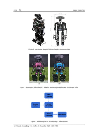
In this section, we report the results of the experiments carried out to understand the performance of
the Tiny-YOLO on a NVIDIA Jetson NX Xavier. All of the experiments were carried out in real time. First,
we tasked the robot to detect team members by detecting the color of the body. As shown in Figure 9, the
robot was commanded to detect two team members, one of which was colored cyan and the other magenta.
The system detects the cyan robot with a dark purple bounding box and the magenta robot with solid red.
From the results in Figure 9(a), we see that the robot recognized both team members with a frame rate of
30 FPS for detection and 29 FPS for capturing the image. Figure 9(b) shows the results when the system was
commanded to detect the magenta robot alone on the field, which was achieved with detection and capture
rates of about 29 FPS. We placed the robot away from the front line and near the goal area for this
experiment.](https://image.slidesharecdn.com/9332089emk-240109041137-f1779cc5/85/Tiny-YOLO-distance-measurement-and-object-detection-coordination-system-for-the-BarelangFC-robot-6-320.jpg)

![ ISSN: 2088-8708
Int J Elec & Comp Eng, Vol. 13, No. 6, December 2023: 6926-6939
6934
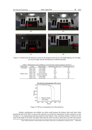
its distance at about 158.75 cm with capture and detection rates of 16 FPS and 15 FPS, respectively, and the
system was also able to generate the coordinates for the other robot that was measured and detected. We
carried out this experiment several times under different conditions, and the results are given in Table 3. An
average error of about 0.75% was found in the distance estimation. A comparison with the results from other
authors shows that in [27], the researchers implemented a CNN method and reported an average error of
4.7% in estimating the robot distance, while Pathi et al. [28] used a Euclidean method with an RGB camera
and achieved an average distance error of 3.5%. Sudin et al. [29] carried out distance estimation using an
analytic geometric estimation (AGE) and produced an average error of 1.35%. Vajgl et al. [30] estimated the
distance between cars in a parking situation using a YOLOv3 with an average error of 0.46%; however, this
work did not involve moving objects such as mobile or humanoid robots that need to detect an object directly
in a real-time situation.
For the position estimation, we experimented by commanding the robot to move to grids 34, 35, and
36, as shown in Figure 14, before passing the ball. The estimation results from the ZED camera can be seen
in Table 4, and the results of this experiment can be seen in Figure 15. Figure 15(a) shows that the robot
stayed in grid 34 and then kicked the ball, whereas Figures 15(b) and 15(c) display the robot’s position in
grid 35 before kicking the ball, and Figure 15(d) depicts the robot’s position in grid 36. This grid position
was set as the starting point that the robot that should reach before kicking the ball.
Figure 1. Results of measuring how much farther the robot’s distance can be detected using a roulette ruler
Table 3. Distance measurement statuses for different initial conditions of the robot
Robot
position
Illumination
values (LUX)
Actual distance (cm) Estimated distance (cm) Error (%) Robot heading (°) Status
Right side 125.8 655 653 0.31 −39 Detected
125.8 330 329 0.30 −42 Detected
125.8 317 315 0.63 −31 Detected
125.8 345 342 0.87 −3 Detected
Left side 125.8 359 356 0.84 −19 Detected
125.8 420 417 0.71 −9 Detected
125.8 530 526 0.75 4 Detected
125.8 440 433 1.59 −10 Detected
The aim of this research was to create a robot to take part in the Kontes Robot Indonesia (KRI)
contest, held once a year. In 2021, one of the themes of the competition was to command the robot to pass the
ball in the same way as a human playing soccer, on the field shown in Figure 16 with a length of 8 m and a
width of 5 m. The rule was that the robot should chase the ball on the field, and then pass it through the
middle line on the field to a team member. The experiment carried out in this work therefore aimed to verify
that our method could achieve cooperation while playing soccer. As can be seen from Figure 17, the cyan
robot first passed the ball to the middle line of the field, and the magenta robot then chased the ball and
kicked it to the other side of the line until it reached the goal. The performance of our robots in the
competition can be watched in [31] minutes 48:38 on the BarelangFC side. The real test in the competition
showed that our robot could pass the ball very well in cooperation with another robot.](https://image.slidesharecdn.com/9332089emk-240109041137-f1779cc5/85/Tiny-YOLO-distance-measurement-and-object-detection-coordination-system-for-the-BarelangFC-robot-9-320.jpg)


![Int J Elec & Comp Eng ISSN: 2088-8708
Tiny-YOLO distance measurement and object detection coordination system for the … (Susanto)
6937
5. CONCLUSION
This paper has presented an implementation of a deep learning method called Tiny-YOLO in which
an NVIDIA Jetson NX Xavier was used to detect the ball, the goal, and the allay simultaneously. Moreover,
robot cooperation was achieved during the competition. Our Tiny-YOLO employed approximately 512 to
1,024 convolutional filters, which generated a significant number of parameters, leading to large memory
requirements and a limited detection area with a slow response. Although these drawbacks could not be
avoided, we overcame this problem by using a NVIDIA Jetson NX Xavier, with outstanding results, by
detecting and estimating the object distance in a parallel manner using a ZED camera. All of the experiments
were carried out on a real-time application. To verify the proposed object detection system, we altered the
environmental light over a range from 4.3 to 125.8 lux, and found that the confidence score for the cyan robot
was higher than for the magenta robot. We also estimated the robot distance under illumination of 125.8 lux
with different angles of robot headings for both the magenta and cyan robots. All of these experiments were
applied to the competition, and it was shown that the robot could recognize a team member and pass the ball
toward it. However, when passing the ball to the other robot, an error sometimes arose, because the ball was
moving away from the landmarks after being kicked by the robot. In future work, we will therefore focus on
how to allow the robot to chase a ball that is moving away from the original landmark without error.
ACKNOWLEDGMENTS
This research was fully funded by Politeknik Negeri Batam.
REFERENCES
[1] G. Tuna, A. Tuna, E. Ahmetoglu, and H. Kuscu, “A survey on the use of humanoid robots in primary education: Prospects,
research challenges and future research directions,” Cypriot Journal of Educational Sciences, vol. 14, no. 3, pp. 361–373, Sep.
2019, doi: 10.18844/cjes.v14i3.3291.
[2] Y. Lau, D. G. H. Chee, X. P. Chow, S. H. Wong, L. J. Cheng, and S. T. Lau, “Humanoid robot-assisted interventions among
children with diabetes: A systematic scoping review,” International Journal of Nursing Studies, vol. 111, Nov. 2020, doi:
10.1016/j.ijnurstu.2020.103749.
[3] T. N. Beran, J. R. Pearson, and B. Lashewicz, “Implementation of a humanoid robot as an innovative approach to child life
interventions in a Children’s Hospital: Lofty goal or tangible reality?” Frontiers in Psychology, vol. 12, Apr. 2021, doi:
10.3389/fpsyg.2021.639394.
[4] J. Yang, J. Jeong, E. R. Jamzuri, and J. Baltes, “Humanoid robot magic show performance,” Multimedia Tools and Applications,
Mar. 2023, doi: 10.1007/s11042-023-14690-w.
[5] D. Rato, F. Correia, A. Pereira, and R. Prada, “Robots in games,” International Journal of Social Robotics, vol. 15, no. 1,
pp. 37–57, Jan. 2023, doi: 10.1007/s12369-022-00944-4.
[6] M. Andtfolk, L. Nyholm, H. Eide, and L. Fagerström, “Humanoid robots in the care of older persons: A scoping review,”
Assistive Technology, vol. 34, no. 5, pp. 518–526, Sep. 2022, doi: 10.1080/10400435.2021.1880493.
[7] E. Maiettini, G. Pasquale, V. Tikhanoff, L. Rosasco, and L. Natale, “A weakly supervised strategy for learning object detection on
a humanoid robot,” in 2019 IEEE-RAS 19th International Conference on Humanoid Robots (Humanoids), Oct. 2019,
pp. 194–201, doi: 10.1109/Humanoids43949.2019.9035067.
[8] E. R. Jamzuri, H. Mandala, and J. Baltes, “A fast and accurate object detection algorithm on humanoid marathon robot,”
Indonesian Journal of Electrical Engineering and Informatics (IJEEI), vol. 8, no. 1, Mar. 2020, doi:
10.52549/ijeei.v8i1.1960.
[9] S. N. Aslan, A. Ucar, and C. Guzelis, “Semantic segmentation for object detection and grasping with humanoid robots,” in 2020
Innovations in Intelligent Systems and Applications Conference (ASYU), Oct. 2020, pp. 1–6, doi:
10.1109/ASYU50717.2020.9259887.
[10] S. N. Aslan, B. Taşçı, A. Uçar, and C. Güzeli˙ş, “Learning to move an object by the humanoid robots by using deep reinforcement
learning,” in Intelligent Environments 2021, {IOS} Press, 2021.
[11] J. Redmon and A. Farhadi, “YOLOv3: An incremental improvement,” arXiv preprint arXiv:1804.02767, Apr. 2018.
[12] S. Susanto, F. A. Putra, and R. Analia, “XNOR-YOLO: the high precision of the ball and goal detecting on the Barelang-FC robot
soccer,” in 2020 3rd International Conference on Applied Engineering (ICAE), Oct. 2020, pp. 1–5, doi:
10.1109/ICAE50557.2020.9350386.
[13] M. Fourmy, D. Atchuthan, N. Mansard, J. Sola, and T. Flayols, “Absolute humanoid localization and mapping based on IMU Lie
group and fiducial markers,” in 2019 IEEE-RAS 19th International Conference on Humanoid Robots (Humanoids), Oct. 2019,
pp. 237–243, doi: 10.1109/Humanoids43949.2019.9035005.
[14] V. S. Raghavan, D. Kanoulas, C. Zhou, D. G. Caldwell, and N. G. Tsagarakis, “A study on low-drift state estimation for
humanoid locomotion, using LiDAR and kinematic-inertial data fusion,” in 2018 IEEE-RAS 18th International Conference on
Humanoid Robots (Humanoids), Nov. 2018, pp. 1–8, doi: 10.1109/HUMANOIDS.2018.8624953.
[15] T. Zhang, E. Uchiyama, and Y. Nakamura, “Dense RGB-D SLAM for humanoid robots in the dynamic humans environment,” in
2018 IEEE-RAS 18th International Conference on Humanoid Robots (Humanoids), Nov. 2018, pp. 270–276, doi:
10.1109/HUMANOIDS.2018.8625019.
[16] R. Sheikh, S. OBwald, and M. Bennewitz, “A combined RGB and depth descriptor for SLAM with humanoids,” in 2018
IEEE/RSJ International Conference on Intelligent Robots and Systems (IROS), Oct. 2018, pp. 1718–1724, doi:
10.1109/IROS.2018.8593768.
[17] A. Rioux and W. Suleiman, “Autonomous SLAM based humanoid navigation in a cluttered environment while transporting a
heavy load,” Robotics and Autonomous Systems, vol. 99, pp. 50–62, Jan. 2018, doi: 10.1016/j.robot.2017.10.001.
[18] D. A. Nguyen and A. Shimada, “Global path and local motion planning for humanoid climbing robot using Kinect sensor,” in
Advances in Asian Mechanism and Machine Science, 2022, pp. 109–122.](https://image.slidesharecdn.com/9332089emk-240109041137-f1779cc5/85/Tiny-YOLO-distance-measurement-and-object-detection-coordination-system-for-the-BarelangFC-robot-12-320.jpg)
![ ISSN: 2088-8708
Int J Elec & Comp Eng, Vol. 13, No. 6, December 2023: 6926-6939
6938
[19] H. Jahanshahi, M. Jafarzadeh, N. N. Sari, V.-T. Pham, V. Van Huynh, and X. Q. Nguyen, “Robot motion planning in an unknown
environment with danger space,” Electronics, vol. 8, no. 2, Feb. 2019, doi: 10.3390/electronics8020201.
[20] J. Hartfill, “Feature-based Monte Carlo localization in the RoboCup humanoid soccer league,” M.S. thesis, University of
Hamburg, 2019.
[21] M. Dalmasso, A. Garrell, J. E. Dominguez, P. Jimenez, and A. Sanfeliu, “Human-robot collaborative multi-agent path planning
using Monte Carlo tree search and social reward sources,” in 2021 IEEE International Conference on Robotics and Automation
(ICRA), May 2021, pp. 10133–10138, doi: 10.1109/ICRA48506.2021.9560995.
[22] W. Fang, L. Wang, and P. Ren, “Tinier-YOLO: A real-time object detection method for constrained environments,” IEEE Access,
vol. 8, pp. 1935–1944, 2020, doi: 10.1109/ACCESS.2019.2961959.
[23] L. E. Ortiz, V. E. Cabrera, and L. M. G. Goncalves, “Depth data error modeling of the ZED 3D vision sensor from stereolabs,”
ELCVIA Electronic Letters on Computer Vision and Image Analysis, vol. 17, no. 1, Jun. 2018, doi: 10.5565/rev/elcvia.1084.
[24] E. Adil, M. Mikou, and A. Mouhsen, “A novel algorithm for distance measurement using stereo camera,” CAAI Transactions on
Intelligence Technology, vol. 7, no. 2, pp. 177–186, Jun. 2022, doi: 10.1049/cit2.12098.
[25] Susanto, F. Azmi, and R. Analia, “Trigonometry algorithm for ball heading prediction of Barelang-FC goal keeper,” in 2018
International Conference on Applied Engineering (ICAE), Oct. 2018, pp. 1–6, doi: 10.1109/INCAE.2018.8579361.
[26] Susanto, R. Saputra, and R. Analia, “A control strategy to estimate the robot position of Barelang-FC striker,” in 2019 2nd
International Conference on Applied Engineering (ICAE), Oct. 2019, pp. 1–5, doi: 10.1109/ICAE47758.2019.9221736.
[27] Rahul and B. B. Nair, “Camera-based object detection, identification and distance estimation,” in 2018 2nd International
Conference on Micro-Electronics and Telecommunication Engineering (ICMETE), Sep. 2018, pp. 203–205, doi:
10.1109/ICMETE.2018.00052.
[28] S. K. Pathi, A. Kiselev, A. Kristoffersson, D. Repsilber, and A. Loutfi, “A novel method for estimating distances from a robot to
humans using egocentric RGB camera,” Sensors, vol. 19, no. 14, Jul. 2019, doi: 10.3390/s19143142.
[29] M. N. Sudin, S. Abdullah, and M. F. Nasudin, “Humanoid localization on robocup field using corner intersection and geometric
distance estimation,” International Journal of Interactive Multimedia and Artificial Intelligence, vol. 5, no. 7, 2019, doi:
10.9781/ijimai.2019.04.001.
[30] M. Vajgl, P. Hurtik, and T. Nejezchleba, “Dist-YOLO: fast object detection with distance estimation,” Applied Sciences, vol. 12,
no. 3, Jan. 2022, doi: 10.3390/app12031354.
[31] Institut Teknologi Bandung, Indonesia. KRI Nasional 2020 Day 3, KRSBI Humanoid (Kontes Robot Sepak Bola Indonesia -
Humanoid). (Nov. 20, 2020) Accessed: Nov.20, 2020. [Online Video]. Available: https://youtu.be/rOPWiIajqw0.
BIOGRAPHIES OF AUTHORS
Susanto received a B.A.Sc. in Electrical Engineering from Politeknik Elektronika
Negeri Surabaya in 2008, and an M.Sc. in Electrical and Control Engineering from National
Chiao Tung University in 2016. Currently, he is a Lecturer at the Department of Electrical
Engineering at Politeknik Negeri Batam. His research interests include control systems,
robotics, artificial intelligence, and biomedical applications. He can be contacted at email:
susanto@polibatam.ac.id.
Jony Arif Ricardo Silitonga received his B.A.Sc. in Electrical Engineering from
Politeknik Negeri Batam in 2022. Currently, he is working as an Equipment Engineer at PT.
Infineon Technologies. He can be reached at email: jonyarifricardo17@gmail.com.
Riska Analia achieved a B.A.Sc. in Electrical Engineering from Bandung
Institute of Technology in 2013 and an M.Sc. in Electrical and Control Engineering from
National Chiao Tung University in 2016. Currently, she is working as a lecturer in the
Department of Electrical Engineering at Politeknik Negeri Batam. She can be reached at
email: riskaanalia@polibatam.ac.id.](https://image.slidesharecdn.com/9332089emk-240109041137-f1779cc5/85/Tiny-YOLO-distance-measurement-and-object-detection-coordination-system-for-the-BarelangFC-robot-13-320.jpg)