Download to read offline

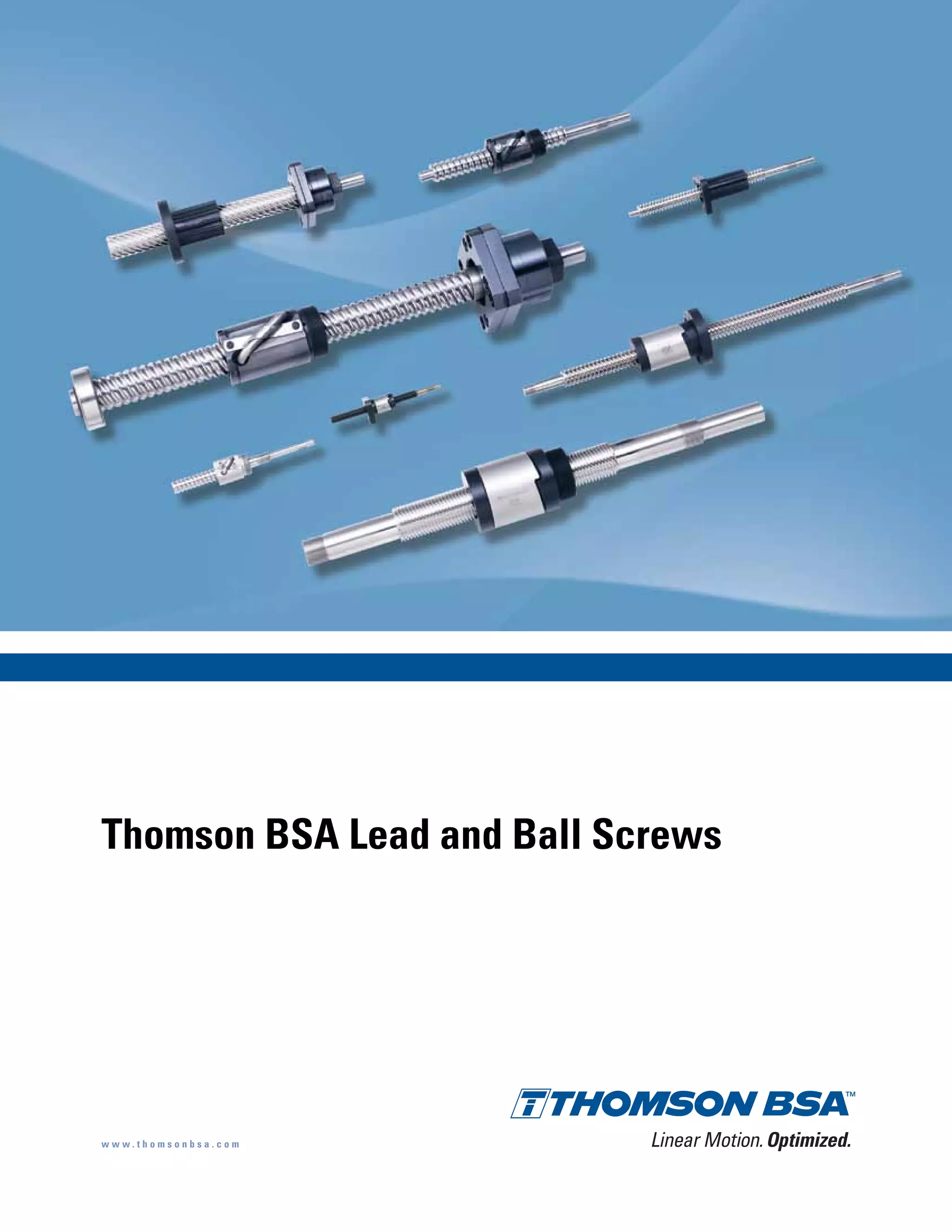
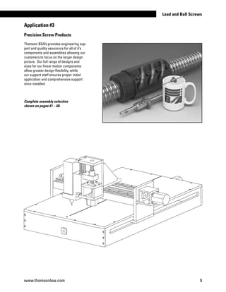
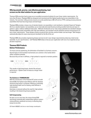
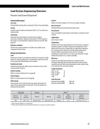
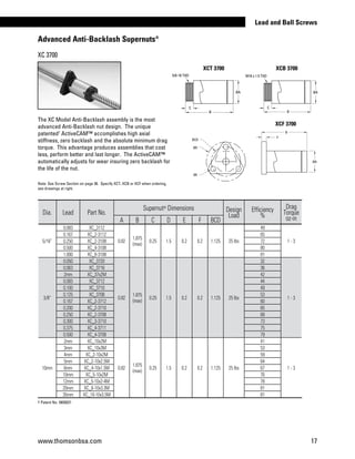
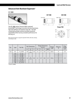
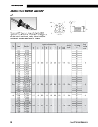
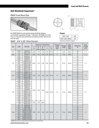
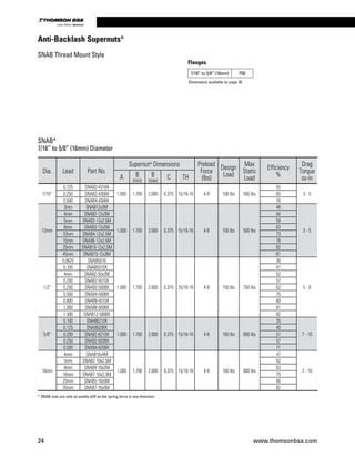
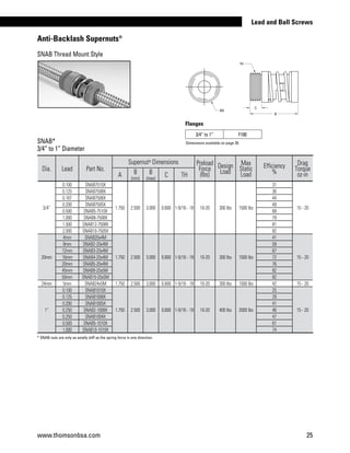
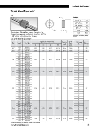
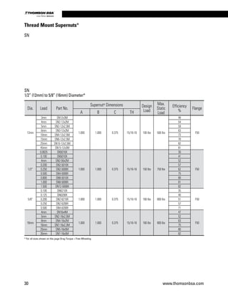
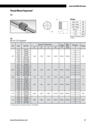
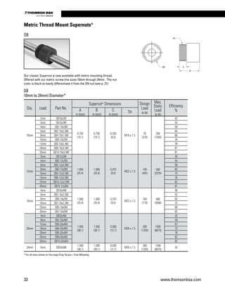
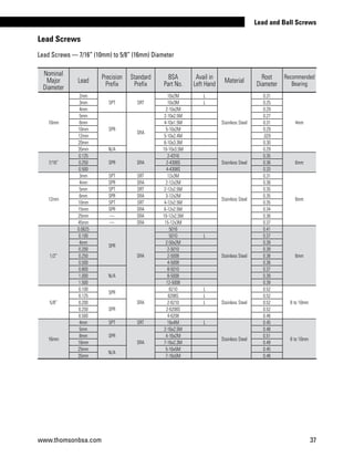
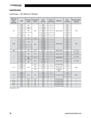
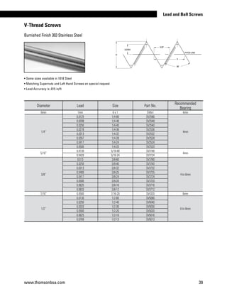


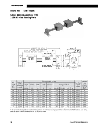
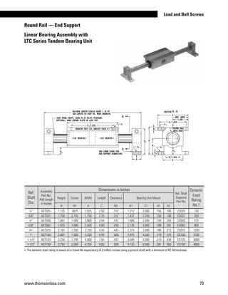

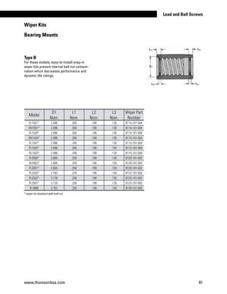
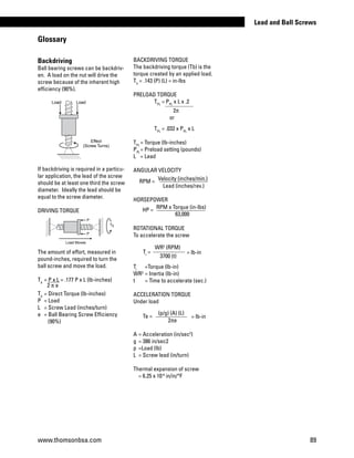


Thomson BSA produces precision lead screws and anti-backlash supernuts for linear motion applications. Their patented ActiveCAM technology provides high axial stiffness and minimal drag torque while eliminating backlash. This allows for smooth, precise positioning without needing a high preload force. The internally lubricated plastic nuts can operate without additional lubrication and the assemblies are resistant to corrosion and vibration. Thomson BSA offers a wide variety of lead screws and mounting options to suit different load and speed requirements.


![Getting Started with Apache Spark: Big Data Made Simple [Free Meetup]](https://cdn.slidesharecdn.com/ss_thumbnails/apachesparkgettingstarted-260203175547-8361bcc3-thumbnail.jpg?width=640&height=640&fit=bounds)


