Download as PDF, PPTX

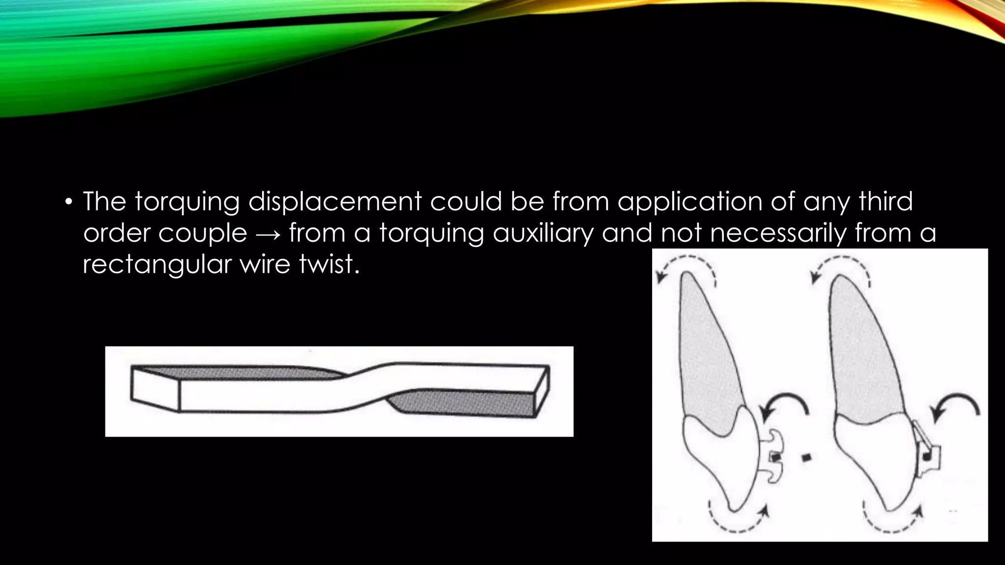


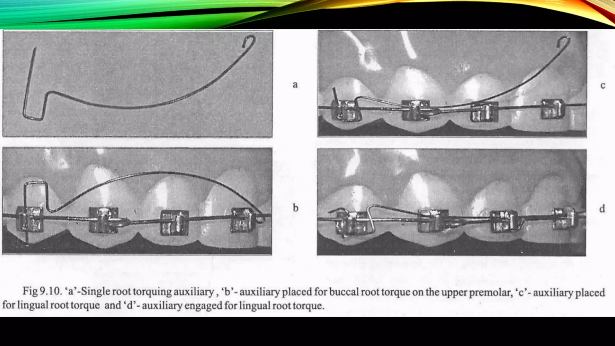
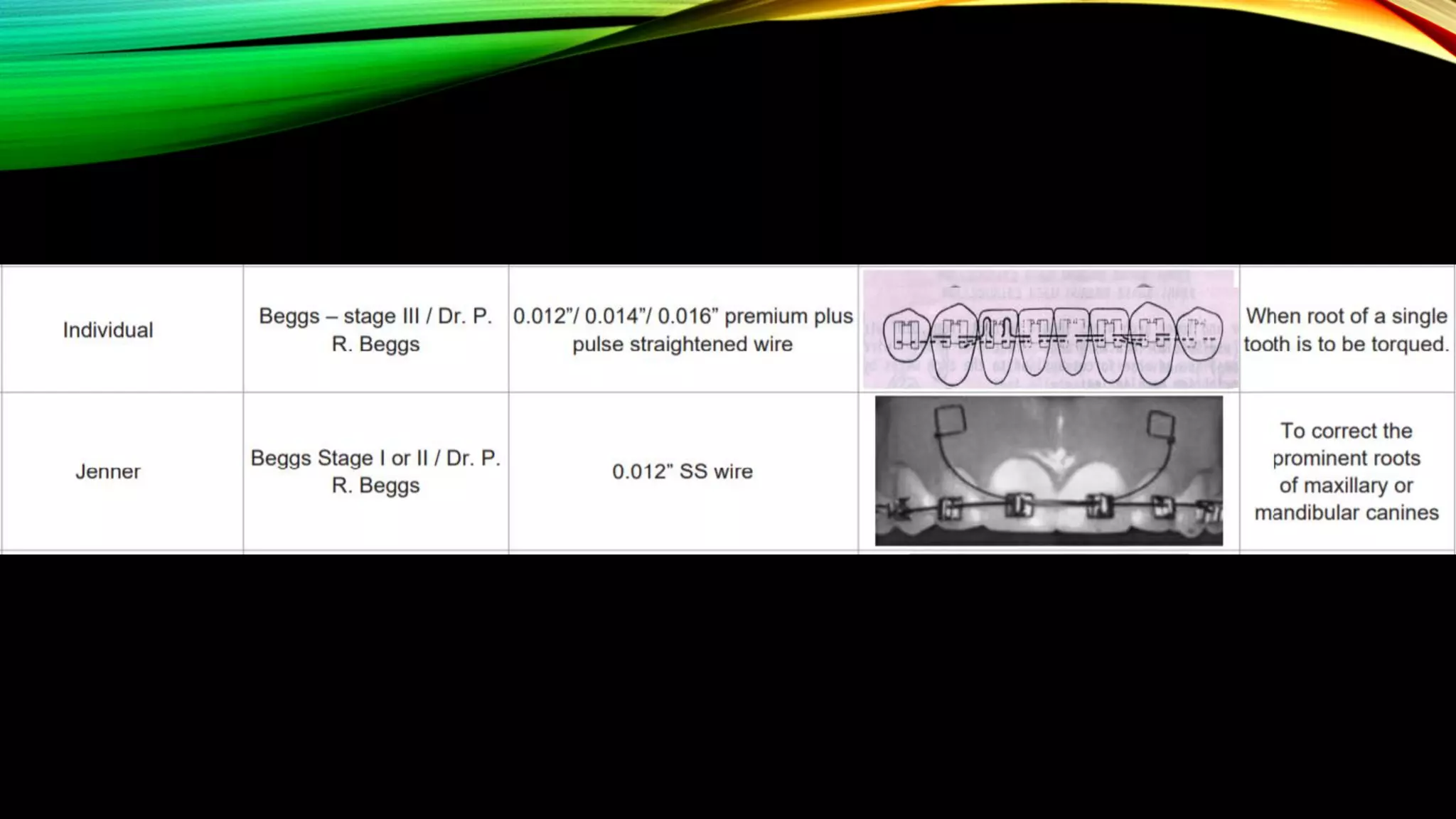


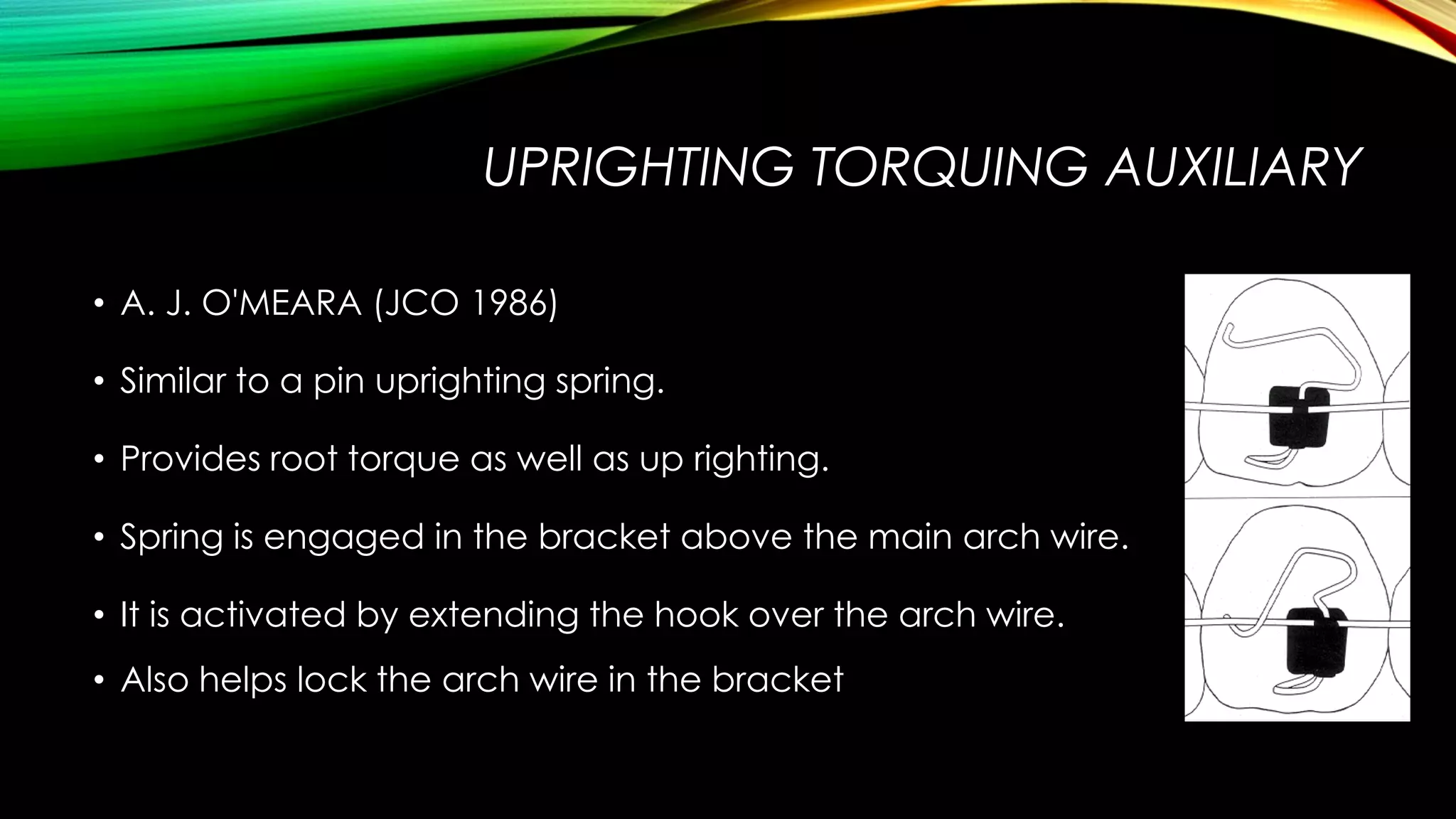
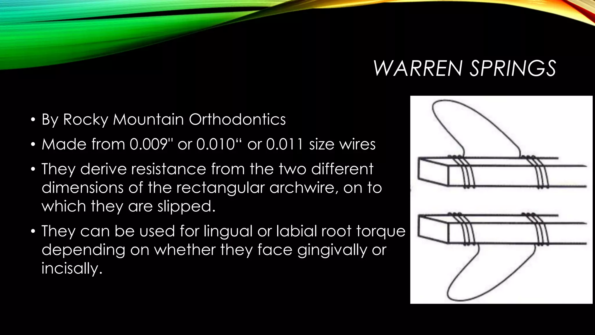

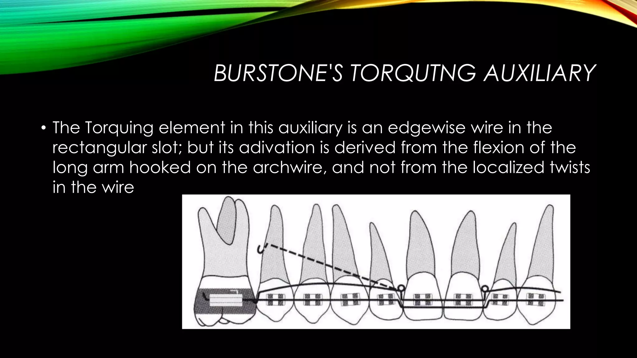

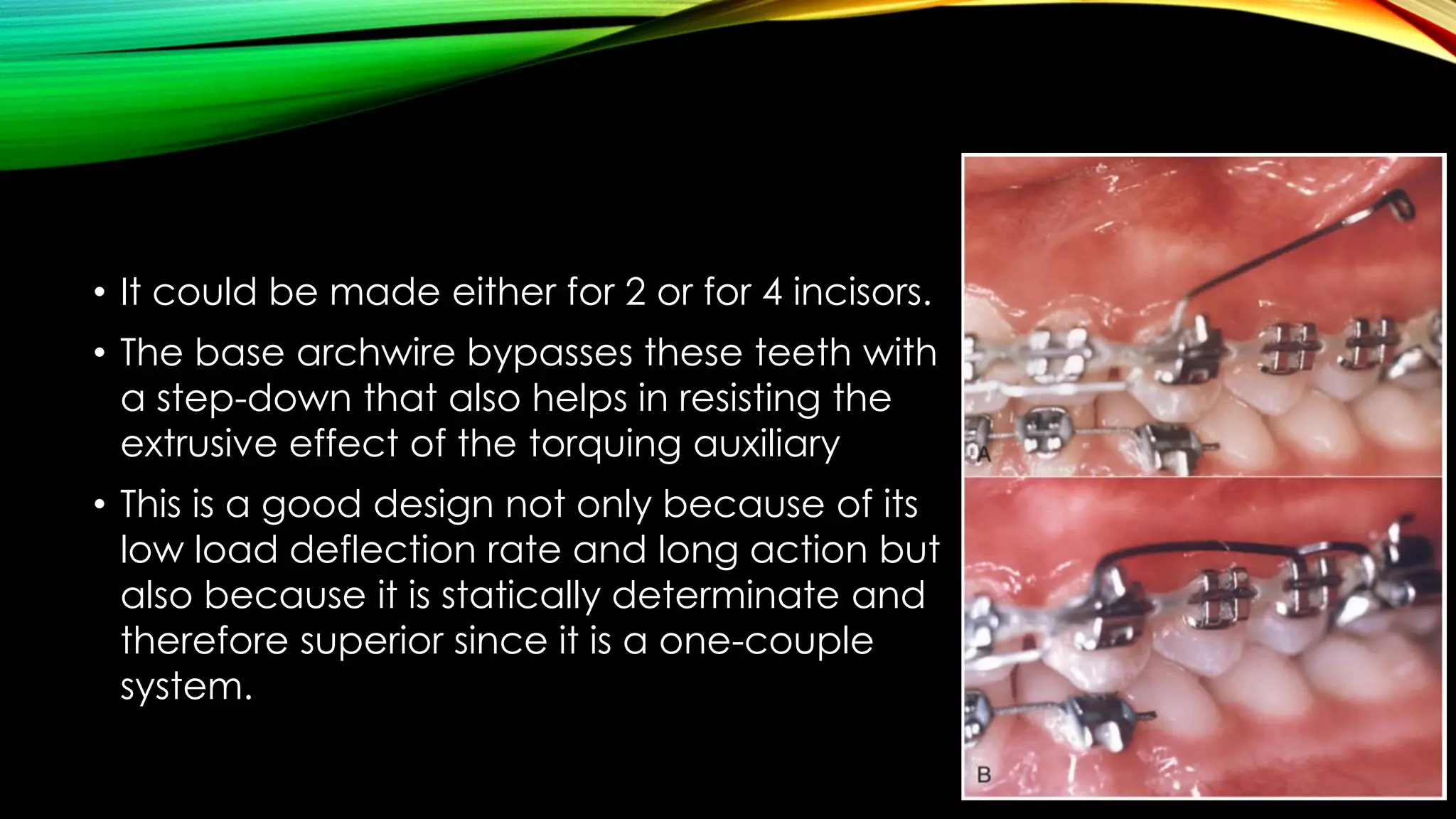


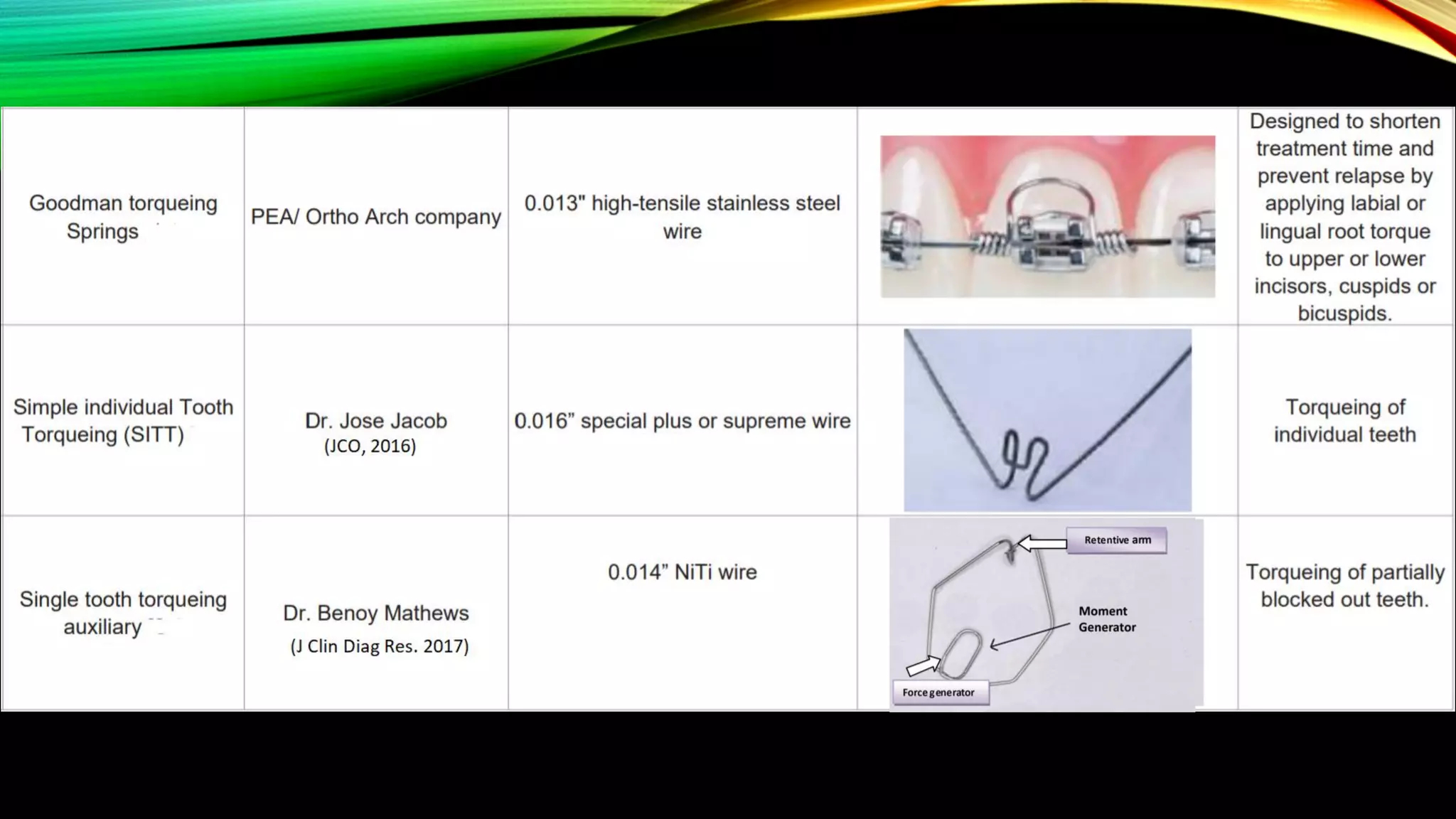


The document discusses various types of torquing auxiliaries used in orthodontics, detailing their historical development, design, and application for achieving optimal tooth movement. It highlights the significance of torque in orthodontic treatment, including different mechanisms for applying torque and specific designs for various teeth. Several auxiliary designs are described, including those for labial and lingual root torque, alongside modifications and adaptations for unique clinical situations.


