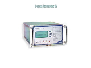
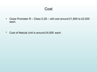
Tariff Metering At Hub Power Station Presented by : Hammad Ali Khan
Overview of the Presentation Defining Metering & Data Collection System Metering Scheme at Hub Power Station Annual Accuracy Check Activity Problems Identified in Current System Proposed Solution Q &A Session
What Is Metering and Data Collection? This refers to the electronic collection of the energy values registered by electricity meters. Active and reactive energy meters produce pulses, each representing a quantity of energy.  The number of pulses counted in, say, 30 minutes is a metered amount of energy known as a half-hour demand.
Metering Scheme at Hub Power Metering Panels Layout Outstations Meters
Metering Panels Layout Outstation 1 Outstation 2 E E I E I E I E I E I E I I I E MW MVar MW MVar MW MW MVar MVar Main Check Line 1 Line 2 Line 1 Line 2
Outstations Outstations connected to the meters provide the means of logging these cumulative demand values. They have the ability to retain that information in memory until such time as it is collected by a central computer or remote collector station.
Outstations Outstation 1 Outstation 2 HUBCO (Remote Collector) WAPDA (Remote Collector) Hub Power Station (Local Collector)
Outstations Kenda's software, known as MDCS-SG, is  running in a local system at the power station itself and in two remote systems. Operating in conjunction with  KENDA'S METEOR RANGE OF REMOTE DATA-COLLECTION  outstations  The MDCS-SG software acquires metering data for the specified demand period, stores it in a database and performs calculations to provide total values and costs for billing purposes.
Energy Meters Static Energy Meters from CEWE INSTRUMENTS (Sweden) 2 Models used-Active Type CEP 32 and Reactive Type CEQ 32 In total there are 8 meters installed It generates output in the form of pulses for 80 ms (adjustable) Accuracy Class 0.2s Each pulse is equivalent to 100KWh
Accuracy Check on Energy Meters Power Purchase Agreement (PPA) calls for a regular accuracy check on the tariff meters. A detailed procedure is maintained which highlights step by step the activity.
Equipment Required 3 Phase Voltage and Current Injection Test Set (Freja 300) GEC Injection Test Plug Test Leads Accuracy Check Equipment-Class 0.1 ( 2 Nos.) Local Interrogation Unit and lead for Outstation Programming Clamp on Meters
Order of Activities Performed Breaking of Seals on Main Panel Accuracy Check on Main Meters on Line # 1 Accuracy Check on Main Meters on Line # 2 Synchronization of Outstation 1 Breaking of Seals on Check Panel Accuracy Check on Main Meters on Line # 1 Accuracy Check on Main Meters on Line # 2 Synchronization of Outstation 2 Sealing of Both Panels Completion of Paper Work
Accuracy Check Setup Layout WAPDA HUBCO I in I ret Voltage Calsoft, PWS 2.3 L & G, TVE,102/3 I in I ret Volt FREJA 300
Overview of the Activity Readings on Dial, Outstation 1 & 2 were noted before breaking seals of the  Main Panel After this, VT fuses associated with Line 1 Energy Meters (2 Nos.) were identified. They were removed. Readings on Dial, Outstation 1 & 2 related with Line 1 Energy Meters were noted. The appropriate test socket for testing Line 1 meters was identified. The test plug (already prepared beforehand) was inserted into the test socket (ensuring that all pins enter the socket at the same time).
Overview of the Activity With the help of Clamp on Meter, it was ensured that the concerned CT was appropriately shorted. All injection tests identified in procedure were performed with results noted down on a sheet of paper. Once again Meter Dial, Outstation 1 & 2 readings were noted immediately after the test. VT fuses removed were reinserted. Steps repeated for Line 2 Energy Meters (2 Nos.).
Synchronization of Outstation Clock The 2 Outstation clocks have drifted with respect to one another and with respect to Pakistan Standard Time (PST). It is therefore possible for each Outstation to register slightly different demand data for each half an hour period. It is desirable to resolve this issue to enable direct comparison between the data from both Outstations.
Procedure for Synchronization  Laptop having LIU (Local Interrogation Unit) software was used. Setup Parameters from Outstation was downloaded onto a Floppy Disk through LIU.  Appropriate Outstation Fuse Link was removed. Internal batteries were also removed (Outstation completely powered down). DC Supply restored with batteries replaced. Setup Parameters uploaded from Floppy Disk back to Outstation. Outstation Clock readjusted to PST. The Energy Meter Dials were readjusted with Outstation Dials through LIU.
VT FUSES
Line 1 Test Socket
Test Plug with Connection Leads
Freja Test Screen Page Voltage & Current Injection Values
Outstation Fuse Links Outstation Fuse Link
Interconnection Cable between Laptop and LIU
Overview of the Activity All steps were repeated for  Check Panel . Results evaluated. Paper work was completed. All panels were sealed. The Activity took 3 Days to complete (1st June – 3 rd  June 2010)
Problems with Current System One meter, Line 2 Watt Meter (Main Panel) was replaced during current activity, the Meter Dial ((L2 WEM) was not working.  Two meters L1 VIC, L2 VEM showed errors higher than the allowed limits. Meter Errors are getting higher, though still within limits but it is a sign that these Energy Meters are now coming close to their end life. Since these Meters are now obsolete, we cannot maintain any spares.  Meters are now getting unreliable (Aging Factor). Failure of Mechanical Dials is troublesome for Operations as it is their source for recording Energy Data.
Proposed Solution Replace Current Energy Meters with Intelligent Digital Meters. Replace Current Outstation System with more upgraded system.
Potential Option Cewe Prometer R can be a feasible replacement for the current outdated meters.  The Nebula Outstation from Kenda Electronic Systems connected to Intelligent Meters  . The Nebula Outstation is able to be configured with various modules and options permitting a flexible configurable metering solution.
Cewe Prometer R
Cost Cewe Prometer R – Class 0.2S – will cost around £1,800 to £2,000 each. Cost of Nebula Unit is around £4,000   each.
Advantages of New System Can read both Tariff and instant readings (e.g. MW,MVAR,MVA,VOLTS,AMPS,FREQUENCY,POWER FACTOR). Offers backward compatibility with pulse meter outputs. It can be configured to automatically synchronize their time against standard Network Time Servers. The use of modern FLASH memory technology means that data does not require any batteries to remain stored in the event of power loss. Number of Meters used will be reduced to 4. The Nebula Unit can be used as a fully compatible replacement  for existing Meteor units.
Q & A SESSION

Tariff Metering

  • 1.
    Tariff Metering AtHub Power Station Presented by : Hammad Ali Khan
  • 2.
    Overview of thePresentation Defining Metering & Data Collection System Metering Scheme at Hub Power Station Annual Accuracy Check Activity Problems Identified in Current System Proposed Solution Q &A Session
  • 3.
    What Is Meteringand Data Collection? This refers to the electronic collection of the energy values registered by electricity meters. Active and reactive energy meters produce pulses, each representing a quantity of energy. The number of pulses counted in, say, 30 minutes is a metered amount of energy known as a half-hour demand.
  • 4.
    Metering Scheme atHub Power Metering Panels Layout Outstations Meters
  • 5.
    Metering Panels LayoutOutstation 1 Outstation 2 E E I E I E I E I E I E I I I E MW MVar MW MVar MW MW MVar MVar Main Check Line 1 Line 2 Line 1 Line 2
  • 6.
    Outstations Outstations connectedto the meters provide the means of logging these cumulative demand values. They have the ability to retain that information in memory until such time as it is collected by a central computer or remote collector station.
  • 7.
    Outstations Outstation 1Outstation 2 HUBCO (Remote Collector) WAPDA (Remote Collector) Hub Power Station (Local Collector)
  • 8.
    Outstations Kenda's software,known as MDCS-SG, is running in a local system at the power station itself and in two remote systems. Operating in conjunction with KENDA'S METEOR RANGE OF REMOTE DATA-COLLECTION outstations The MDCS-SG software acquires metering data for the specified demand period, stores it in a database and performs calculations to provide total values and costs for billing purposes.
  • 9.
    Energy Meters StaticEnergy Meters from CEWE INSTRUMENTS (Sweden) 2 Models used-Active Type CEP 32 and Reactive Type CEQ 32 In total there are 8 meters installed It generates output in the form of pulses for 80 ms (adjustable) Accuracy Class 0.2s Each pulse is equivalent to 100KWh
  • 10.
    Accuracy Check onEnergy Meters Power Purchase Agreement (PPA) calls for a regular accuracy check on the tariff meters. A detailed procedure is maintained which highlights step by step the activity.
  • 11.
    Equipment Required 3Phase Voltage and Current Injection Test Set (Freja 300) GEC Injection Test Plug Test Leads Accuracy Check Equipment-Class 0.1 ( 2 Nos.) Local Interrogation Unit and lead for Outstation Programming Clamp on Meters
  • 12.
    Order of ActivitiesPerformed Breaking of Seals on Main Panel Accuracy Check on Main Meters on Line # 1 Accuracy Check on Main Meters on Line # 2 Synchronization of Outstation 1 Breaking of Seals on Check Panel Accuracy Check on Main Meters on Line # 1 Accuracy Check on Main Meters on Line # 2 Synchronization of Outstation 2 Sealing of Both Panels Completion of Paper Work
  • 13.
    Accuracy Check SetupLayout WAPDA HUBCO I in I ret Voltage Calsoft, PWS 2.3 L & G, TVE,102/3 I in I ret Volt FREJA 300
  • 14.
    Overview of theActivity Readings on Dial, Outstation 1 & 2 were noted before breaking seals of the Main Panel After this, VT fuses associated with Line 1 Energy Meters (2 Nos.) were identified. They were removed. Readings on Dial, Outstation 1 & 2 related with Line 1 Energy Meters were noted. The appropriate test socket for testing Line 1 meters was identified. The test plug (already prepared beforehand) was inserted into the test socket (ensuring that all pins enter the socket at the same time).
  • 15.
    Overview of theActivity With the help of Clamp on Meter, it was ensured that the concerned CT was appropriately shorted. All injection tests identified in procedure were performed with results noted down on a sheet of paper. Once again Meter Dial, Outstation 1 & 2 readings were noted immediately after the test. VT fuses removed were reinserted. Steps repeated for Line 2 Energy Meters (2 Nos.).
  • 16.
    Synchronization of OutstationClock The 2 Outstation clocks have drifted with respect to one another and with respect to Pakistan Standard Time (PST). It is therefore possible for each Outstation to register slightly different demand data for each half an hour period. It is desirable to resolve this issue to enable direct comparison between the data from both Outstations.
  • 17.
    Procedure for Synchronization Laptop having LIU (Local Interrogation Unit) software was used. Setup Parameters from Outstation was downloaded onto a Floppy Disk through LIU. Appropriate Outstation Fuse Link was removed. Internal batteries were also removed (Outstation completely powered down). DC Supply restored with batteries replaced. Setup Parameters uploaded from Floppy Disk back to Outstation. Outstation Clock readjusted to PST. The Energy Meter Dials were readjusted with Outstation Dials through LIU.
  • 18.
  • 19.
  • 20.
    Test Plug withConnection Leads
  • 21.
    Freja Test ScreenPage Voltage & Current Injection Values
  • 22.
    Outstation Fuse LinksOutstation Fuse Link
  • 23.
  • 24.
    Overview of theActivity All steps were repeated for Check Panel . Results evaluated. Paper work was completed. All panels were sealed. The Activity took 3 Days to complete (1st June – 3 rd June 2010)
  • 25.
    Problems with CurrentSystem One meter, Line 2 Watt Meter (Main Panel) was replaced during current activity, the Meter Dial ((L2 WEM) was not working. Two meters L1 VIC, L2 VEM showed errors higher than the allowed limits. Meter Errors are getting higher, though still within limits but it is a sign that these Energy Meters are now coming close to their end life. Since these Meters are now obsolete, we cannot maintain any spares. Meters are now getting unreliable (Aging Factor). Failure of Mechanical Dials is troublesome for Operations as it is their source for recording Energy Data.
  • 26.
    Proposed Solution ReplaceCurrent Energy Meters with Intelligent Digital Meters. Replace Current Outstation System with more upgraded system.
  • 27.
    Potential Option CewePrometer R can be a feasible replacement for the current outdated meters. The Nebula Outstation from Kenda Electronic Systems connected to Intelligent Meters . The Nebula Outstation is able to be configured with various modules and options permitting a flexible configurable metering solution.
  • 28.
  • 29.
    Cost Cewe PrometerR – Class 0.2S – will cost around £1,800 to £2,000 each. Cost of Nebula Unit is around £4,000 each.
  • 30.
    Advantages of NewSystem Can read both Tariff and instant readings (e.g. MW,MVAR,MVA,VOLTS,AMPS,FREQUENCY,POWER FACTOR). Offers backward compatibility with pulse meter outputs. It can be configured to automatically synchronize their time against standard Network Time Servers. The use of modern FLASH memory technology means that data does not require any batteries to remain stored in the event of power loss. Number of Meters used will be reduced to 4. The Nebula Unit can be used as a fully compatible replacement for existing Meteor units.
  • 31.
    Q & ASESSION