Example of fire design of the industrial building. This is a fully documented calculation example with direct reference to the actual code provisions. It is based on European Standard ENV 1999-2 (Eurocode 9)
TALAT Lecture 2713
Fire Design Example
Based on European Standard ENV 1999-2
(Eurocode 9)
27 pages
Advanced Level
Updated from the TAS Project :
TAS Leonardo da Vinci program
Training in Aluminium Alloy Structural Design
Date of Issue: 1999
EAA - European Aluminium Association
TALAT 2713 1
2.
2505 Fire DesignExample.
(26 pages)
Table of Contents
2505 Fire Design Example. ..............................................................................................2
1.0 INTRODUCTION.....................................................................................................3
1.1 Description............................................................................................................... 3
1.2 Sketches. .................................................................................................................. 3
1.3 References................................................................................................................ 3
2.0 MATERIALS.............................................................................................................4
2.1 Aluminium. .............................................................................................................. 4
3.0 LOADS. ......................................................................................................................4
3.1 Static loads. .............................................................................................................. 4
3.2 Fire loads.................................................................................................................. 4
4.0 STATIC DESIGN......................................................................................................5
4.1 Results from the normal temperature design. .......................................................... 5
4.2 Load effects in fire design........................................................................................ 5
4.2.1 Beam F. ............................................................................................................. 6
4.2.2 Column B........................................................................................................... 6
5. THERMAL CALCULATIONS. .................................................................................6
5.1 General. ................................................................................................................ 6
5.2 Beam F. .................................................................................................................... 8
5.3 Column B. ................................................................................................................ 9
6.0 CODE CHECKING. ...............................................................................................10
6.1 Beam F. .................................................................................................................. 10
6.2 Column B. .............................................................................................................. 10
7 APPENDIX. ........................................................................................................10
TALAT 2713 2
3.
1.0 INTRODUCTION.
In the fire design example, the structure used in design example for static design is used.
1.1 Description.
The industrial building contain an administration part with offices, wardrobe, meeting
rooms etc and a fabrication hall. The load bearing system consists of frames standing at a
distance of 5000 mm.
In serviceability limit state the max. allowable deflection is 1/250 of span.
The load bearing structure has the following requirement to fire endurance: R60.
1.2 Sketches.
A section of one load bearing frame.
1.3 References.
|1|: ENV 1999. Eurocode 9: Design of aluminium structures. Part 1.1.
General rules.
|2|: ENV 1999. Eurocode 9: Design of aluminium structures. Part 1.2.
Structural fire design. February 1998.
|3|: TALAT. 2700 Design Example No. 1.
|4|: ENV 1991. Eurocode 1: Basis of design and actions on structures. Part 2-2:
Actions on structures – Actions on structures exposed to fire. February 1995.
TALAT 2713 3
4.
2.0 MATERIALS.
2.1 Aluminium.
|1|, 3.2.2 The extrusions are alloy EN AW-6082, temper T6, the plates are EN AW-5083 temper
H24.
Table 2.1 Strength of aluminium alloys.
Alloy f0,2 fu
EN AW-6082 T6 260 MPa 310 MPa
EN AW-5083 H24 250 MPa 340 MPa
|1|, 5.1.1 The partial safety factor for the members: γM1 = 1,10
γM2 = 1,25
|1|, 6.1.1 The partial safety factor for welded connections: γMw = 1,25
|2|, 2.3 The partial safety factor for fire design: γM,fi = 1,0
Table 2.2 Design values of material coefficients.
Modulus of elasticity E = 70 000 MPa
Shear modulus G = 27 000 MPa
Poisson’s ratio ν = 0,3
Coefficient of linear thermal expansion α = 23 x 10-6 per °C
Density ρ = 2 700 kg/m3
3.0 LOADS.
3.1 Static loads.
The static loads are described in static design example.
3.2 Fire loads.
The thermal load is the standard fire curve, which is described as:
|4|, 4.2.2 Θg = 20 + 345 ⋅ log10 (8t + 1)
where: Θg = fire temperature
t = duration in min.
TALAT 2713 4
5.
4.0 STATIC DESIGN.
4.1 Results from the normal temperature design.
The load bearing frame is calculated in static design example. In this example one
column (Column B) and one beam (Beam F) are chosen as example for fire design.
Beam F, (I 570 x 160 x 5 x 15,4). Values from the static design:
MRd = 341 kNm
VRd = 223,5 kN
Column B, (I 200 x 160 x 7 x 16). Values from the static design:
Max utilisation for flexural buckling – HAZ at column base (combination of compression
and bending): U = 0,952
4.2 Load effects in fire design.
The combination rule for actions in fire design is:
∑γ GA ⋅ Gk + ψ 1,1 ⋅ Qk ,1 + ∑ψ 2,i ⋅ Qk ,i + ∑ Ad (t )
where: Gk = characteristic values of permanent actions
Qk,1 = characteristic value of one (the main) variable action
Qk,i = characteristic values of the other variable actions
Ad(t) = design values from actions from fire exposure
γGA = 1,0
ψ1,1 = 0,5
ψ2,i = 0,3
TALAT 2713 5
6.
4.2.1 Beam F.
The critical criteria for Beam F is the bending moment in the middle of the beam. The
load from the crane is the main variable action. The beam is calculated as pinned in both
ends. This will account for some internal actions due to constrained expansion and
deformation.
Gk = 2,75 kN/m
Qk,1 = 50 kN (load from crane)
Qk,2 = 4,125 kN/m (imposed load on roof)
Qk,3 = 11 kN/m (snow load)
Windload gives only suction to the roof, and will for that reason not be included in the
load combination.
1
M fi , Ed = 1,0 ⋅ ⋅ 2,75
kN
(10m )2 + 0,5 ⋅ 50kN ⋅ 10m + 0,3 ⋅ 1 ⋅ 4,125 kN (10m )2
8 m 4 8 m
⋅ (10m ) = 139,8kNm
1 kN
+ 0,2 ⋅ ⋅ 11
2
8 m
4.2.2 Column B.
Column B is calculated with use of the MathCad spread sheet from normal temperature
design. In this spread sheet the partial factors from the combination rule given in 4.2 is
used. In addition a factor of 1.2 is used on the axial load (according to 2, 4.2.2.4).
Max utilisation for flexural buckling – HAZ at column base (combination of compression
and bending): U = 0,39
5. THERMAL CALCULATIONS.
5.1 General.
Comment: To perform the thermal calculations according to |2|, it is need for some tests
values for insulation materials used on aluminium structures. These test values don’t
exist. The calculations may, however, be performed with the available thermal properties
for insulation materials.
In this example Rockwool with a density of 300 kg/m3 is used. The thermal properties
vary with the temperature. This is handle as linear equations for the thermal properties
for the insulation materials.
Thermal conductivity for Rockwool 300 kg/m3:
θ t + θ al
λ p = 0,000215 + 0,035 (W/m°C)
4
TALAT 2713 6
7.
Specific heat forRockwool 300 kg/m3:
θ + θ al
c p = 0,75 ⋅ t + 800 (J/kg°C)
4
Specific heat for aluminium:
|4|, 3.3.2 c al = 0,41 ⋅ θ al + 903 (J/kg°C)
The temperatur rise in an insulated aluminium member can be calculated according to the
following equation. This may easily be done in a spread sheet.
λ p d p Ap 1
(θ − θ al )∆t − (e − 1)∆θ ( t )
φ 10
|4|, 4.2.3.2 ∆θ al ( t ) = ⋅
cal ⋅ ρ al V 1 + φ 3 t
but ∆θ al ( t ) ≥ 0
in which:
c pρ p Ap
φ= dp
calρal V
where: Ap V is the section factor for aluminium alloy members insulated by
fire protection material (m-1)
Ap is the area of the inner surface of the fire protection material,
per unit length of the member (m²/m)
V is the volume of the member per unit length (m³/m)
cal is the specific heat of aluminium alloys (J/kg ºC)
cp is the specific heat of the fire protection material (J/kg ºC)
dp is the thickness of the fire protection material (m)
∆t is the time interval (seconds)
θ(t ) is the ambient gas temperature at time t (ºC)
θ al ( t ) is the aluminium temperature at time t (ºC)
∆θ ( t ) is the increase of the ambient temperature during the time
interval ∆t (ºC)
λp is the thermal conductivity of the fire protection material
(W/m ºC)
ρal is the unit mass of aluminium alloys (kg/m³)
ρp is the unit mass of the fire protection material (kg/m³)
TALAT 2713 7
8.
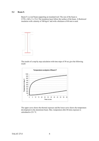
5.2 Beam F.
Beam F is a roof beam supporting an insulated roof. The size of the beam is
I 570 x 160 x 5 x 15,4. The insulation layer follow the surface of the beam. A Rockwool
insulation with a density of 300 kg/m3 and with a thickness of 60 mm is used.
The results of a step by step calculation with time steps of 30 sec give the following
result:
Temperature analysis of Beam F
1000
900
800
Temperature in deg. C
700
600
500
400
300
200
100
0
0 5 10 15 20 25 30 35 40 45 50 55 60
Time in min
The upper curve shows the thermal exposure and the lower curve shows the temperature
development in the aluminium beam. Max. temperature after 60 mins exposure is
calculated to 231 °C.
TALAT 2713 8
9.
5.3 Column B.
Column B is a partly freestanding column which may be exposed by a fire from four
sides. The size of the column is I 200 x 160 x 7 x 16. The insulation is boxed around the
column. The insulation is Rockwool with density 300 kg/m3 and the thickness is 40 mm.
The results of a step by step calculation with time steps of 30 sec give the following
result:
Temperature analysis of Column B
1000,00
900,00
800,00
Temperature in deg. C
700,00
600,00
500,00
Column B
400,00
300,00
200,00
100,00
0,00
0 5 10 15 20 25 30 35 40 45 50 55 60
Time in min
The upper curve shows the thermal exposure and the lower curve shows the temperature
development in the aluminium beam. Max. temperature after 60 mins exposure is
calculated to 225 °C.
TALAT 2713 9
10.
6.0 CODE CHECKING.
6.1 Beam F.
The temperature of Beam F is 232 °C. The alloy is EN-AW 6082 temper T6.
0,65 − 0,38
k 0, 2,θ = 0,65 − ⋅ 32 = 0,48
50
γ M1 1,10
M fi ,t , Rd = k 0, 2,θ ⋅ M Rd ⋅ = 0,48 ⋅ 341kNm ⋅ = 180,0kNm
γ M , fi 1,0
M fi , Ed = 139,8kNm ≤ M fi ,t , Rd = 180,0kNm
6.2 Column B.
The temperature of Colum B is 225 °C. The alloy is EN-AW 6082 temper T6.
0,65 − 0,38
k 0, 2,θ = 0,65 − ⋅ 25 = 0,515
50
U fi ,t , Rd = k 0.2,θ max ⋅ U = 0,515 ⋅ 0,952 = 0,49 ≥ U fi , Ed = 0,39
7 APPENDIX.
6.2 Column B – Appendix to Fire Design. (MathCad 7.0 Pro)
Thermal calculations for Beam F and Column B. (Microsoft Excel 97)
TALAT 2713 10