Handwritten Text Recognition for manuscripts and early printed texts
System for software controlled switch with manual override switch
1. 1
Abstract:
Manual override switch is a featured not commonly found in most IOT system available in market. This feature is useful to help
user from lost control when network connection is down. The device is equipped with a single-pole double-throw (SPDT)
mechanical switch coupled with electronically-controlled relay at the output circuit. The device makes the system robust from
completely loss control.
Index Terms— Internet-Of-Things, smart-home, smart-living, open-source, smart switch, wireless sensor network.
I. INTRODUCTION1
Smart switches allow users to remotely control their
household appliances over the Internet using their
Smartphone. User can also program the switch to on or off
during pre-set schedule, smart switches typically consist of
microcontroller that is programmed to connect or
disconnect electrical circuits via electronic relay.
A modem i.e. wired/wireless transceiver to receive user
command over the Internet/communication network from a
control device such as Smartphone. DC power supply to
power up the electronic hardware unfortunately, if the
microcontroller, electronic relay or power supply is faulty,
or if the network is down, the smart switch is rendered
useless. Hence, users can no longer remotely or physically
power on their household appliances. On that course, a
circuit to avoid lost control on/off switch is introduced.
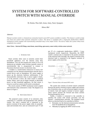
The circuit consists of SPDT mechanical switch coupled
with electronic relay connected to a load. The diagram is as
shown in Figure 1.
II. SWITCHING CIRCUIT
The proposed system consists of an electronic relay
connected to a controller and programmed with software
routine. The relay’s common pin is connected to the
positive terminal of the power supply while its normally-
open and normally-close pins are connected to pin 1T and
pin 2T of a single-pole double-throw (SPDT) / 3-way
mechanical switch, respectively. Meanwhile, the SPDT
switch’s common pin is connected to the positive terminal
of the electrical load. Secondly, the negative terminal of the
electrical load is connected to the negative terminal of
power supply as the return line.
Figure 1: Electronic Relay with manual SPDT switch
The system also consists of current sensors connected
between the positive terminal of power supply and common
pin of electronic relay, as well as between negative terminal
of electric load and negative terminal of power supply.
These sensors measure the forward and return currents
flowing through the circuit.
Finally, a modem is connected to the controller to
interface the system with remote user/entity over the
Internet / communication networks. The designed circuit
allows an electrical load to be controlled as follows:
• Remotely over the Internet/communication networks
from PC/handheld device/Smartphone
• Manually by toggling the SPDT switch on-site
SYSTEM FOR SOFTWARE-CONTROLLED
SWITCH WITH MANUAL OVERRIDE
Dr. Roslee, Wan Adil, Azura, Amry, Nazri, Syargawi,
Mimos Bhd
2. • Automatic shut-off if the system detects over-current
or short-to-ground fault
III. SYSTEM OPERATION
A system to connect and disconnect an electrical circuit
powering a load, comprising ARM processor sitting on a
Texas board CC1350 programmed with software routine for
controlling an electronic relay [3]. A single-pole double-
throw (SPDT) switch is a mechanical device connected in
series with the electronic relay. There are two current
sensors measuring incoming and outgoing current to
determine state of the operation either ON/OFF.
A modem to communicate with remote entity via
wireless communication networks is managed by the
Contiki operating system [1].
The controller connected to electronic relay and
programmed with software routine to energize or de-
energize the relay. The relay’s common pin is connected to
the positive terminal of the power supply. In one
embodiment of the present invention, the normally-open
and normally-closed pins of the relay are connected to pin
1T and 2T of the SPDT switch, respectively.
In another embodiment of the present invention, the
normally-open and normally-closed pins of the relay can
also be connected to pin 2T and 1T of the SPDT switch,
respectively. The common pin of the SPDT switch is
connected to the positive terminal of the electrical load,
while the negative terminal of the electrical load is
connected to the negative terminal of the power supply.
A current sensor is connected between the positive
terminal of power supply and common pin of the electronic
relay to measure the forward current. The sensor’s output is
connected to the controller in order for the software to
acquire its reading. Another current sensor is connected
between the negative terminal of the electrical load and
negative terminal of power supply to measure the return
current. The sensor’s output is connected to the controller in
order for the software to acquire its reading.
A modem connected to the controller for interfacing the
system to remote user/entity via wired/wireless
communication networks.
IV. SOFTWARE OPERATION
The controller via its software routine periodically reads
the forward and return currents measured by the both
current sensors. Refers to figure 2, if both forward and
return currents are zero, the system is currently in OFF
state. If both forward and return currents are non-zero, the
system is currently in ON state.
Figure 2: ON/OFF determination flow chart
When the controller, via the modem, receives command
from a remote user/entity over the Internet/communication
network to change its state to ON, the controller via its
programmed software routine shall first determine its
current state using software defined routine. Figure 3 below
shows the flowchart.
Figure 3: ON flow chart
If the system is currently ON, no further action is taken
by the software routine. If the system is currently OFF, the
software routine checks if the relay is energized. If yes, the
software routine de-energizes the relay. Else, the software
routine energizes the relay.
Figure 4: OFF flow chart
3. 3
The software routine re-determines the state of system
using defined software to confirm it has transitioned to ON
state. If not, the software previous routine presumed. Else,
the software routine, via the modem, updates the current
state of system to remote user/entity over the
Internet/communication networks.
V. HARDWARE OPERATION
If the electrical load connected to the system is not
operating, the system is said to be in OFF state. If the SPDT
switch is currently connected to 1T pin, user can toggle the
switch to 2T pin to change the state of system to ON.
The electrical load connected to the system shall now be
operating. Else, if the SPDT switch is currently connected
to 2T pin, user can toggle the switch to 1T pin to change the
state of system to ON. The electrical load connected to the
system of shall now be operating.
If the electrical load connected to the system is operating,
the system is said to be in ON state. If the SPDT switch is
currently connected to 1T pin, user can toggle the switch to
2T pin to change the state of system to OFF.
The electrical load connected to the system shall now
stop operating. Else, if the SPDT switch is currently
connected to 2T pin, user can toggle the switch to 1T pin to
change the state of system to OFF. The electrical load
connected to the system shall now stop operating.
VI. OVER CURRENT PROTECTION
While the system is in ON state, the software routine
constantly measures forward and return currents via the
current sensors. The software routine computes the absolute
current difference by using the following formula :
i.e. currentdiff = |currentforward – currentreturn|
If the current difference is greater than minimum
acceptable current, a short-to-ground fault has occurred.
The software automatically shuts off the system by
energizing/de-energizing the relay if it is currently de-
energized/energized.
Figure 5: Over current & ground fault flow chart
If the current difference is lower than minimum
acceptable current, the software routine checks whether the
forward/return current is above a maximum threshold
current. If yes, an over-current condition has occurred. The
software routine automatically shuts off the system by
energizing/de-energizing the relay if it is currently de-
energized/energized.
VII. RESULT
VIII. CONCLUSION
Software-controlled switch with manual-override
function is an excellent function when network connection
is down. It helps user to resolve total lost control.
APPENDIX
ACKNOWLEDGMENT
REFERENCES
[1] Adam Dunkels, Contiki Programming Course: Hand-On Session
Notes , Swedish Institute of Computer Science
[2] Introduction to wireless sensor networks with 6LoWPAN and
Contiki, Vrije Universiteit Brussel, Faculteit
Ingenieurswetenschappen
[3] Texas, www.ti.com
[4]
[5]
[6]
![• Automatic shut-off if the system detects over-current
or short-to-ground fault
III. SYSTEM OPERATION
A system to connect and disconnect an electrical circuit
powering a load, comprising ARM processor sitting on a
Texas board CC1350 programmed with software routine for
controlling an electronic relay [3]. A single-pole double-
throw (SPDT) switch is a mechanical device connected in
series with the electronic relay. There are two current
sensors measuring incoming and outgoing current to
determine state of the operation either ON/OFF.
A modem to communicate with remote entity via
wireless communication networks is managed by the
Contiki operating system [1].
The controller connected to electronic relay and
programmed with software routine to energize or de-
energize the relay. The relay’s common pin is connected to
the positive terminal of the power supply. In one
embodiment of the present invention, the normally-open
and normally-closed pins of the relay are connected to pin
1T and 2T of the SPDT switch, respectively.
In another embodiment of the present invention, the
normally-open and normally-closed pins of the relay can
also be connected to pin 2T and 1T of the SPDT switch,
respectively. The common pin of the SPDT switch is
connected to the positive terminal of the electrical load,
while the negative terminal of the electrical load is
connected to the negative terminal of the power supply.
A current sensor is connected between the positive
terminal of power supply and common pin of the electronic
relay to measure the forward current. The sensor’s output is
connected to the controller in order for the software to
acquire its reading. Another current sensor is connected
between the negative terminal of the electrical load and
negative terminal of power supply to measure the return
current. The sensor’s output is connected to the controller in
order for the software to acquire its reading.
A modem connected to the controller for interfacing the
system to remote user/entity via wired/wireless
communication networks.
IV. SOFTWARE OPERATION
The controller via its software routine periodically reads
the forward and return currents measured by the both
current sensors. Refers to figure 2, if both forward and
return currents are zero, the system is currently in OFF
state. If both forward and return currents are non-zero, the
system is currently in ON state.
Figure 2: ON/OFF determination flow chart
When the controller, via the modem, receives command
from a remote user/entity over the Internet/communication
network to change its state to ON, the controller via its
programmed software routine shall first determine its
current state using software defined routine. Figure 3 below
shows the flowchart.
Figure 3: ON flow chart
If the system is currently ON, no further action is taken
by the software routine. If the system is currently OFF, the
software routine checks if the relay is energized. If yes, the
software routine de-energizes the relay. Else, the software
routine energizes the relay.
Figure 4: OFF flow chart](data:image/gif;base64,R0lGODlhAQABAIAAAAAAAP///yH5BAEAAAAALAAAAAABAAEAAAIBRAA7)