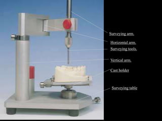
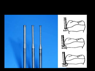
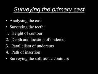
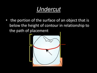
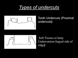
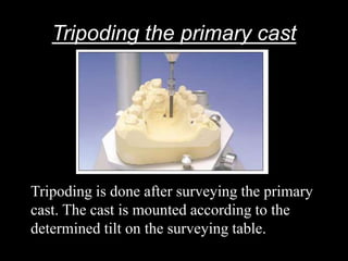
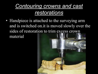
Surveyor And Surveying
Under the guidance if:
Dr.
Dr.
Dr.
Dr.
Presented By:
Sheikh Mohammad Hyder
BDS Final Year(12-13)
85
Department Of Prosthodontics
Surveying
The procedure of locating or delineating the
contour and position of the abutment teeth and
associated structures before designing a
removable partial denture.
Or
An analysis and comparison of the prominence
of intraoral contours associated with the
fabrication of a prosthesis.
Surveyor
An instrument used to determine the relative
parallelism of two or more surfaces of the teeth
or other parts of the cast of a dental arch.
Or
An instrument used in the construction of a
removable partial denture to locate and
delineate the contours and relative positions of
abutment teeth and associated structures.(GPT)
Horizontal arm.
Surveying arm.
Surveying tools.
Vertical arm.
Cast holder
Surveying table
Objectives of surveying
• To design a RPD that its rigid and flexible components
are appropriately positioned to obtain good retention
and bracing.
• To determine the path of insertion of a prosthesis such
that there is no interference to insertion along this path
• To mark the height of contour of the area (hard /soft
tissues) above the under cut.
• To mark the survey lines(height of contour of a tooth)
• To mark the undesirable undercuts under which the
prosthesis should not extend.
Types of surveyors
1. NEY surveyor.
2. Jelenko or Will’s surveyor
3. William’s surveyor
the structure of these surveyors is basically
similar with mild differences from one
another .generally the William’s surveyor is
more flexible.
Parts of a surveyor
1. Cast holder or surveying table.
2. Vertical arm.
3. Horizontal arm.
4. Surveying arm.
5. Surveying tools.
Cast holder/Surveying table
Stand placed over the surveying platform. It has
a base and a table to place a cast. The cast can
be locked in any position on the table with the
help of a locking device.The table is attached
to the base with the help of a ball and socket
joint. The joint facilitates to tilt the table.
Vertical arm
Arises vertically from the surveying platform.
Supports the super structure (horizontal and the
surveying arm)
Horizontal arm
Extends horizontally from the top of vertical
arm. Designed to support the surveying arm
and its free end.
NEY surveyor has a revolving horizontal arm
William’s surveyor has a revolving horizontal
arm with a joint in the middle.
Surveying arm
Extend vertically from the free end of the
horizontal arm. It is parallel to the vertical arm.
It can move upwards and downwards . The
lower end of this arm has a mandrel into which
tools used for surveying can be locked in.
Surveying tools
Tools which can be attached to the mandrel of
the surveying arm.
They are of different types:-
Analyzing rod.
Carbon markers.
Wax knife.
Under-cut guage.
Analysing rod
Its a solid cylindrical metal rod, the first tool to be
used during surveying. It is used to determine the
parallelism of tooth surfaces before marking the
surveyor line. It also helps to determine arbitrarly
the path of insertion.
Acts like a tangent to the convex surface of the
object being surveyed. Its more like a diagnostic
survey tool.
Helps to analyze the location of the height of
contours, the presence and absence of favourable
and unfavourable undercuts for a path of insertion
Carbon markers
Resemble the lead points commercially available
for the micro tip pencils. They are used to
draw survey lines which denote the height of
contour of the tooth.
Undercut guage
It is a high precision instrument used to measure linear
dimension of any structure, the depth and location of
the undercut in 3 dimentions.
According to Stewart:
1. 0.010 inch
2. 0.015 inch
3. 0.020 inch
According to MC Craken:
1. 0.010 inch
2. 0.020 inch
3. 0.030 inch
Wax knife
Used to trim the excess wax while surveying the
wax pattern and also to block the undesired
undercuts parallel the path of insertion.
Survey lines
Height of contour of the abutment tooth marked by
a carbon marker.
A line drawn on a tooth/teeth of a cast by means of a
surveyor for the purpose of determining the
positions of various parts of clasp.
Classified as :
• High
• Medium
• Low
• Diagonal
High Survey Line
• Found near the
occlusal surface of a
tooth often parallel to
the gingival margin
• It results from
abnormal inclination of
the teeth
• lingual surfaces of the
lower teeth and buccal
surfaces of the upper
teeth.
• Wrought wire clasp
used
Medium Survey Line
• It is situated across the
center of the tooth
• Exhibits a slight
occlusogingival incline
from the near zone to
the far zone.
•
• Aker’s or Roach clasp
Low Survey Line
• It is situated close to
and parallel to the
gingival margin.
• It frequently occurs as
a result of marked
inclination of the tooth
and may also occur on
conically shaped tooth.
• Modified T clasp
Diagonal Survey Line
• It travels diagonally
from near the occlusal
surface in the near
zone to the gingiva in
the far zone.
• Reverse criclet clasp
Uses of surveying
1. Surveying the diagnostic cast
2. Tripoding the cast
3. Transferring tripod marks to another cast
4. Contouring wax patterns
5. Contouring cast restorations
6. Placing internal attachments and rests
7. Surveying the master cast
Surveying the primary cast
• Analysing the cast
• Surveying the teeth:
1. Height of contour
2. Depth and location of undercut
3. Parallelism of undercuts
4. Path of insertion
• Surveying the soft tissue contours
Undercut
• the portion of the surface of an object that is
below the height of contour in relationship to
the path of placement
Types of undercuts
Tooth Undercuts (Proximal
undercuts)
Soft Tissues or bony
Undercuts(on lingual side of
ridge)
Tripoding the primary cast
Tripoding is done after surveying the primary
cast. The cast is mounted according to the
determined tilt on the surveying table.
Anterior and Posterior tilt
Right and Left tilt
Transferring the tripod marks .
• The procedure is done to orient the master cast
using the same angulation of the primary cast
• Commonly used reference points are
1. Distal margional rige of the first premolar
2. Incisal edge of lateral incisor
3. Lingual cuspal tip of the first
premolar(opposite to the side where the other
two points were marked)
Contouring the wax patterns
Contouring crowns and cast
restorations
• Handpiece is attached to the surveying arm
and is switched on.it is moved slowly over the
sides of restoration to trim excess crown
material
Placing internal attachments
• Intracoronal retainers, occlusal rests can be
created in wax patterns using a rotary handpiece.
• They are later refined on the cast restorations,the
intracoronal retainer is similar to hook or a loop.
The loop like structure is placed within the crown
and the hook is attached to the prosthesis. During
the insertion the hook gets locked into the loop to
provide retention.
Placing internal rest seats
• Large box shaped metalic extensions that
function as intracoronal retainers . They differ
from inetrnal attachments in that they are not
prefabricated and the rest seat formed by the
sound tooth structure, functions as the key-way
Surveying the master cast
• Done to check whether the desired results have
been observed in mouth preparation.
Parallelism of the guiding plane
Depth of undercuts and retention
Height of contour
interference
Surveying ceramic veneer crowns
• The ceramic restoration is placed on the cast
and the height of contour is modified/verified
before final glazing
Guiding planes
vertically parallel surfaces on abutment teeth
or/and dental implant abutments oriented so as
to contribute to the direction of the path of
placement and removal of a removable dental
prosthesis.
Two or more parallel axial surfaces on abutment teeth
which can be used to limit the path of insertion and
improve the stability of a removable prosthesis. Guide
surfaces may occur naturally on teeth but more
commonly need to be prepared.
Path of insertion
the specific direction in which a prosthesis is
placed upon and removed from the abutment
teeth.(GPT)
Single path of insertion
Multiple path of insertion
Two path insertion Rotational path of insertion
Factors influencing the path of
insertion
• Retentive undercuts
• Interference
• Aesthetics
• Guiding planes
• Denture base
• Location of minor connector
• Point of origin of approach arm
Interference
In Maxilla:
• Torus palatinus
• Buccally tipped teeth
• Bony exostoses
In Mandible:
• Lingual torri
• Lingul inclination of
remaining teeth
• Bony exostosis.
Surveyor-Dr Sheikh M Hyder

Surveyor-Dr Sheikh M Hyder

  • 1.
    Surveyor And Surveying Underthe guidance if: Dr. Dr. Dr. Dr. Presented By: Sheikh Mohammad Hyder BDS Final Year(12-13) 85 Department Of Prosthodontics
  • 2.
    Surveying The procedure oflocating or delineating the contour and position of the abutment teeth and associated structures before designing a removable partial denture. Or An analysis and comparison of the prominence of intraoral contours associated with the fabrication of a prosthesis.
  • 3.
    Surveyor An instrument usedto determine the relative parallelism of two or more surfaces of the teeth or other parts of the cast of a dental arch. Or An instrument used in the construction of a removable partial denture to locate and delineate the contours and relative positions of abutment teeth and associated structures.(GPT)
  • 4.
    Horizontal arm. Surveying arm. Surveyingtools. Vertical arm. Cast holder Surveying table
  • 5.
    Objectives of surveying •To design a RPD that its rigid and flexible components are appropriately positioned to obtain good retention and bracing. • To determine the path of insertion of a prosthesis such that there is no interference to insertion along this path • To mark the height of contour of the area (hard /soft tissues) above the under cut. • To mark the survey lines(height of contour of a tooth) • To mark the undesirable undercuts under which the prosthesis should not extend.
  • 6.
    Types of surveyors 1.NEY surveyor. 2. Jelenko or Will’s surveyor 3. William’s surveyor the structure of these surveyors is basically similar with mild differences from one another .generally the William’s surveyor is more flexible.
  • 7.
    Parts of asurveyor 1. Cast holder or surveying table. 2. Vertical arm. 3. Horizontal arm. 4. Surveying arm. 5. Surveying tools.
  • 8.
    Cast holder/Surveying table Standplaced over the surveying platform. It has a base and a table to place a cast. The cast can be locked in any position on the table with the help of a locking device.The table is attached to the base with the help of a ball and socket joint. The joint facilitates to tilt the table.
  • 9.
    Vertical arm Arises verticallyfrom the surveying platform. Supports the super structure (horizontal and the surveying arm)
  • 10.
    Horizontal arm Extends horizontallyfrom the top of vertical arm. Designed to support the surveying arm and its free end. NEY surveyor has a revolving horizontal arm William’s surveyor has a revolving horizontal arm with a joint in the middle.
  • 11.
    Surveying arm Extend verticallyfrom the free end of the horizontal arm. It is parallel to the vertical arm. It can move upwards and downwards . The lower end of this arm has a mandrel into which tools used for surveying can be locked in.
  • 12.
    Surveying tools Tools whichcan be attached to the mandrel of the surveying arm. They are of different types:- Analyzing rod. Carbon markers. Wax knife. Under-cut guage.
  • 13.
    Analysing rod Its asolid cylindrical metal rod, the first tool to be used during surveying. It is used to determine the parallelism of tooth surfaces before marking the surveyor line. It also helps to determine arbitrarly the path of insertion. Acts like a tangent to the convex surface of the object being surveyed. Its more like a diagnostic survey tool. Helps to analyze the location of the height of contours, the presence and absence of favourable and unfavourable undercuts for a path of insertion
  • 15.
    Carbon markers Resemble thelead points commercially available for the micro tip pencils. They are used to draw survey lines which denote the height of contour of the tooth.
  • 16.
    Undercut guage It isa high precision instrument used to measure linear dimension of any structure, the depth and location of the undercut in 3 dimentions. According to Stewart: 1. 0.010 inch 2. 0.015 inch 3. 0.020 inch According to MC Craken: 1. 0.010 inch 2. 0.020 inch 3. 0.030 inch
  • 18.
    Wax knife Used totrim the excess wax while surveying the wax pattern and also to block the undesired undercuts parallel the path of insertion.
  • 19.
    Survey lines Height ofcontour of the abutment tooth marked by a carbon marker. A line drawn on a tooth/teeth of a cast by means of a surveyor for the purpose of determining the positions of various parts of clasp. Classified as : • High • Medium • Low • Diagonal
  • 20.
    High Survey Line •Found near the occlusal surface of a tooth often parallel to the gingival margin • It results from abnormal inclination of the teeth • lingual surfaces of the lower teeth and buccal surfaces of the upper teeth. • Wrought wire clasp used
  • 21.
    Medium Survey Line •It is situated across the center of the tooth • Exhibits a slight occlusogingival incline from the near zone to the far zone. • • Aker’s or Roach clasp
  • 22.
    Low Survey Line •It is situated close to and parallel to the gingival margin. • It frequently occurs as a result of marked inclination of the tooth and may also occur on conically shaped tooth. • Modified T clasp
  • 23.
    Diagonal Survey Line •It travels diagonally from near the occlusal surface in the near zone to the gingiva in the far zone. • Reverse criclet clasp
  • 24.
    Uses of surveying 1.Surveying the diagnostic cast 2. Tripoding the cast 3. Transferring tripod marks to another cast 4. Contouring wax patterns 5. Contouring cast restorations 6. Placing internal attachments and rests 7. Surveying the master cast
  • 25.
    Surveying the primarycast • Analysing the cast • Surveying the teeth: 1. Height of contour 2. Depth and location of undercut 3. Parallelism of undercuts 4. Path of insertion • Surveying the soft tissue contours
  • 26.
    Undercut • the portionof the surface of an object that is below the height of contour in relationship to the path of placement
  • 27.
    Types of undercuts ToothUndercuts (Proximal undercuts) Soft Tissues or bony Undercuts(on lingual side of ridge)
  • 28.
    Tripoding the primarycast Tripoding is done after surveying the primary cast. The cast is mounted according to the determined tilt on the surveying table.
  • 29.
  • 30.
  • 31.
    Transferring the tripodmarks . • The procedure is done to orient the master cast using the same angulation of the primary cast • Commonly used reference points are 1. Distal margional rige of the first premolar 2. Incisal edge of lateral incisor 3. Lingual cuspal tip of the first premolar(opposite to the side where the other two points were marked)
  • 32.
  • 33.
    Contouring crowns andcast restorations • Handpiece is attached to the surveying arm and is switched on.it is moved slowly over the sides of restoration to trim excess crown material
  • 34.
    Placing internal attachments •Intracoronal retainers, occlusal rests can be created in wax patterns using a rotary handpiece. • They are later refined on the cast restorations,the intracoronal retainer is similar to hook or a loop. The loop like structure is placed within the crown and the hook is attached to the prosthesis. During the insertion the hook gets locked into the loop to provide retention.
  • 35.
    Placing internal restseats • Large box shaped metalic extensions that function as intracoronal retainers . They differ from inetrnal attachments in that they are not prefabricated and the rest seat formed by the sound tooth structure, functions as the key-way
  • 36.
    Surveying the mastercast • Done to check whether the desired results have been observed in mouth preparation. Parallelism of the guiding plane Depth of undercuts and retention Height of contour interference
  • 37.
    Surveying ceramic veneercrowns • The ceramic restoration is placed on the cast and the height of contour is modified/verified before final glazing
  • 38.
    Guiding planes vertically parallelsurfaces on abutment teeth or/and dental implant abutments oriented so as to contribute to the direction of the path of placement and removal of a removable dental prosthesis.
  • 39.
    Two or moreparallel axial surfaces on abutment teeth which can be used to limit the path of insertion and improve the stability of a removable prosthesis. Guide surfaces may occur naturally on teeth but more commonly need to be prepared.
  • 40.
    Path of insertion thespecific direction in which a prosthesis is placed upon and removed from the abutment teeth.(GPT) Single path of insertion
  • 41.
    Multiple path ofinsertion Two path insertion Rotational path of insertion
  • 42.
    Factors influencing thepath of insertion • Retentive undercuts • Interference • Aesthetics • Guiding planes • Denture base • Location of minor connector • Point of origin of approach arm
  • 43.
    Interference In Maxilla: • Toruspalatinus • Buccally tipped teeth • Bony exostoses In Mandible: • Lingual torri • Lingul inclination of remaining teeth • Bony exostosis.