Definition as perIEEE standards
As per IEEE standards, Surge
/ Lightning Arrester is
“ a protective device for limiting
surge voltages on the equipment by
diverting surge current and
returning the device to its original
status. It is capable of repeating
these functions as specified”
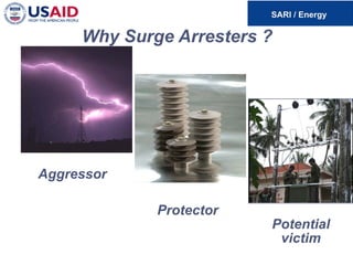
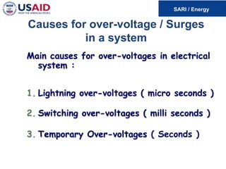
Causes for over-voltage/ Surges
in a system
Main causes for over-voltages in electrical
system :
1. Lightning over-voltages ( micro seconds )
2. Switching over-voltages ( milli seconds )
3. Temporary Over-voltages ( Seconds )
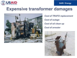
8.
Over-voltages & electricalsystem
Electrical equipments like transformers,
motors are designed to withstand pre-
determined values of impulse voltages.
Higher levels & multiple strikes of impulse
voltages cause the insulation to break down
thus creating chaos in the system.
9.
Over-voltages in electricalsystem
Protection of electrical devises are made
possible by connecting protective devises -
Surge Arresters in parallel.
These devises should have variable
resistance as a function of the voltage
magnitude to divert over-voltage to ground.
Gapless Zinc Oxide Surge Arresters are
the latest protective devises used to keep
the system voltages well within limits.
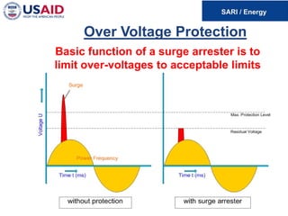
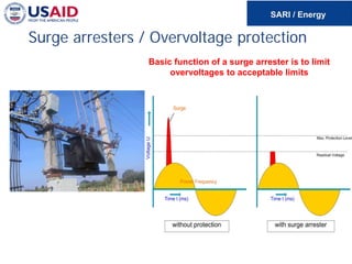
Surge Arresters /Over-voltage protection
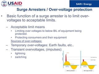
• Basic function of a surge arrester is to limit over-
voltages to acceptable limits.
– Acceptable limit means
• Limiting over voltages to below BIL of equipment being
protected.
• Protecting consumers and their equipment
Sources of over-voltages:
– Temporary over-voltages: Earth faults, etc..
– Transient overvoltages, (impulses):
• lightning
• switching
12.
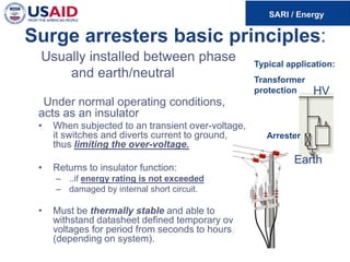
Surge arresters basicprinciples:
Usually installed between phase
and earth/neutral
Under normal operating conditions,
acts as an insulator
• When subjected to an transient over-voltage,
it switches and diverts current to ground,
thus limiting the over-voltage.
• Returns to insulator function:
– ..if energy rating is not exceeded
– damaged by internal short circuit.
• Must be thermally stable and able to
withstand datasheet defined temporary over-
voltages for period from seconds to hours,
(depending on system).
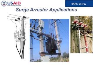
Typical application:
Transformer
protection
Earth
Arrester
HV
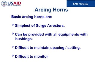
Arcing Horns
Basic arcinghorns are:
Simplest of Surge Arresters.
Can be provided with all equipments with
bushings.
Difficult to maintain spacing / setting.
Difficult to monitor
16.
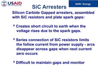
SiC Arresters
Silicon CarbideGapped arresters, assembled
with SiC resistors and plate spark gaps:
Creates short circuit to earth when the
voltage rises due to the spark gaps.
Series connection of SiC resistors limits
the follow current from power supply - arcs
disappear across gaps when next current
zero occurs
Difficult to maintain gaps and monitor
17.
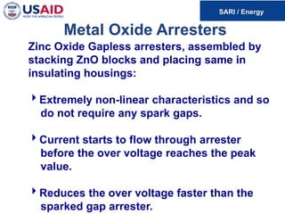
Metal Oxide Arresters
ZincOxide Gapless arresters, assembled by
stacking ZnO blocks and placing same in
insulating housings:
Extremely non-linear characteristics and so
do not require any spark gaps.
Current starts to flow through arrester
before the over voltage reaches the peak
value.
Reduces the over voltage faster than the
sparked gap arrester.
18.
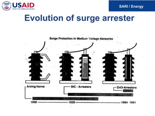
TWO SIGNIFICANT DEVELOPMENTS
Followingtwo significant fundamental
developments occurred in the arrester
technology:
SiC resistors and plate spark gaps were
replaced by Metal oxide resistors without
plate gaps.
Housings of the arresters made of
porcelain were replaced with new ones
made of polymer material.
Arrester Classification
Arresters canbe classified based on
following:
Based on type of housing
a) Porcelain Housed Arresters
b) Polymeric Housed Arresters
Based on Energy Handling
Distribution class
Station class I to IV
21.
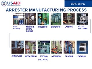
Surge Arrester MajorComponents
The major components of LA’s are:
• Outer housing - porcelain or polymeric.
• ZnO Blocks.
• Springs to keep blocks in place.
• Spacers / Heat sinks
• Pressure Relief vents
• End caps for preventing moisture entry.
• Terminals for connecting to line & earth.
• Mounting clamps
22.
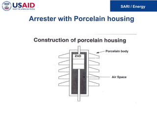
Outer Housing
Main functionsare:
• Provide the contained space in which the
ZnO Blocks are assembled.
• Ensure heat transfer from the blocks to
outside atmosphere.
• Have necessary parameters to ensure
withstand of electrical system properties.
• Prevent tracking and flashover.
23.
Zinc Oxide Blocks
HEARTof the Surge Arrester:
• Must remain as a non-conducting path
during the normal operating voltage &
ensure only over-voltages are conducted
to earth.
• Minimum leakage current & have good heat
dissipation.
• Quick response - absorb incoming surges
without time delay.
• Maintain good thermal stability for long life.
24.
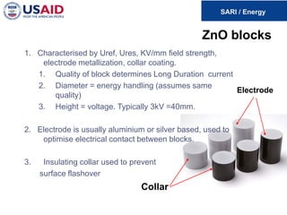
ZnO blocks
Electrode
Collar
1. Characterisedby Uref, Ures, KV/mm field strength,
electrode metallization, collar coating.
1. Quality of block determines Long Duration current
2. Diameter = energy handling (assumes same
quality)
3. Height = voltage. Typically 3kV =40mm.
2. Electrode is usually aluminium or silver based, used to
optimise electrical contact between blocks.
3. Insulating collar used to prevent
surface flashover
25.
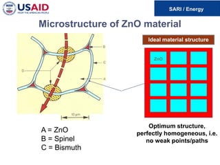
Microstructure of ZnOmaterial
Ideal material structure
ZnO
ZnO
A = ZnO
B = Spinel
C = Bismuth
Optimum structure,
perfectly homogeneous, i.e.
no weak points/paths
26.
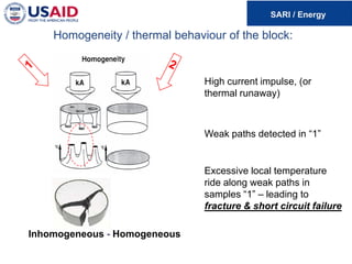
Homogeneity / thermalbehaviour of the block:
Inhomogeneous - Homogeneous
High current impulse, (or
thermal runaway)
Weak paths detected in “1”
Excessive local temperature
ride along weak paths in
samples “1” – leading to
fracture & short circuit failure
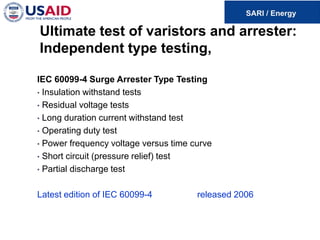
Ultimate test ofvaristors and arrester:
Independent type testing,
IEC 60099-4 Surge Arrester Type Testing
• Insulation withstand tests
• Residual voltage tests
• Long duration current withstand test
• Operating duty test
• Power frequency voltage versus time curve
• Short circuit (pressure relief) test
• Partial discharge test
Latest edition of IEC 60099-4 released 2006
31.
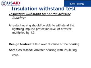
Insulation withstand test
Insulationwithstand test of the arrester
housing:
Arrester housing should be able to withstand the
lightning impulse protection level of arrester
multiplied by 1.3
Design feature: Flash over distance of the housing
Samples tested: Arrester housing with insulating
core.
32.
Surge arresters /Overvoltage protection
Basic function of a surge arrester is to limit
overvoltages to acceptable limits
33.
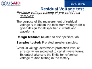
Residual Voltage test
Residualvoltage testing of pro-rated test
samples:
The purpose of the measurement of residual
voltage is to obtian the maximum voltages for a
given design for all specified currents and
waveforms.
Design feature: Related to disc specification
Samples tested: Prorated arrester samples.
Residual voltage determines protection level of
arrester when subjected to certain wave forms.
Its output also sets the limits for reference
voltage routine testing in the factory.
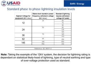
Standard phase tophase lightning insulation levels
Note: Taking the example of the 12kV system, the decision for lightning rating is
dependant on statistical likely-hood of lightning, type of neutral earthing and type
of over-voltage protection used as standard.
37.
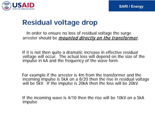
Residual voltage drop
Inorder to ensure no loss of residual voltage the surge
arrester should be mounted directly on the transformer.
If it is not then quite a dramatic increase in effective residual
voltage will occur. The actual loss will depend on the size of the
impulse in kA and the frequency of the wave form.
For example if the arrester is 4m from the transformer and the
incoming impulse is 5kA on a 8/20 then the rise in residual voltage
will be 5kV. If the impulse is 20kA then the loss will be 20kV.
If the incoming wave is 4/10 then the rise will be 10kV on a 5kA
impulse
38.
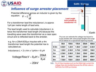
Influence of surgearrester placement
Potential difference across an inductor is given by the
equation:
For a transformer lead the inductance L is approx
1μH per metre length of lead wire.
The lead length used to calculate inductance L is
twice the transformer lead length (H) because the
travelling wave sees the transformer as a near open
circuit and is reflected back to the arrester.
e.g. for a 20kA 8/20μs impulse with a 4m
transformer lead length the potential rise is
calculated as:
Inductance L = 2 x 4m x 1μH/m = 8 μH
kV
s
kA
H
V
20
8
20
8
Rise
Voltage
=
×
=
µ
µ
dt
di
L
V =
Lead Length
from arrester to
transformer = H
Earth
Thus we can estimate the voltage rise beyond a
surge arrester with various lead lengths and surge
kA as follows for a typical 8/20 lightning impulse
5kA 10kA 15kA 20kA 40kA
0.5m 0.6kV 1.2kV 1.8kV 2.5kV 5.0kV
1m 1.2kV 2.5kV 3.7kV 5.0kV 10kV
2m 2.5kV 5.0kV 7.5kV 10kV 20kV
4m 5kV 10kV 15kV 20kV 40kV
6m 7.5kV 15kV 23kV 30kV 60kV
N.B.: For 4/10μs impulses such as the 65kA high current the
voltage rises are doubled because the dt time value is
half that of an 8/20 μs impulse
39.
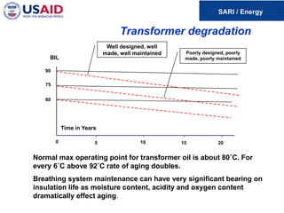
Transformer degradation
Well designed,well
made, well maintained Poorly designed, poorly
made, poorly maintained
Time in Years
BIL
90
75
60
0 5 10 15 20
Normal max operating point for transformer oil is about 80˚C. For
every 6˚C above 92˚C rate of aging doubles.
Breathing system maintenance can have very significant bearing on
insulation life as moisture content, acidity and oxygen content
dramatically effect aging.
40.
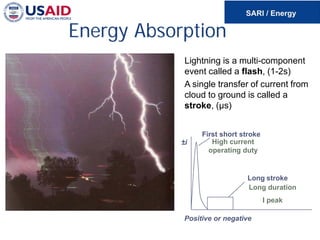
Energy Absorption
Lightning isa multi-component
event called a flash, (1-2s)
A single transfer of current from
cloud to ground is called a
stroke, (µs)
Positive or negative
Long stroke
First short stroke
±i High current
operating duty
Long duration
I peak
41.
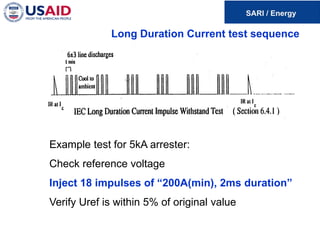
Long duration currentwithstand
Test to confirm that arrester can withstand rated long
duration line discharge duty.
The purpose of the measurement of LD test is to verify the
arrester ability to withstand multiple long duration impulses, i.e.
Switching / multipulse induced overvoltages while energised at
power frequency voltage.
Design feature: Energy handling, thermal stability.
Samples tested: Prorated arrester samples.
42.
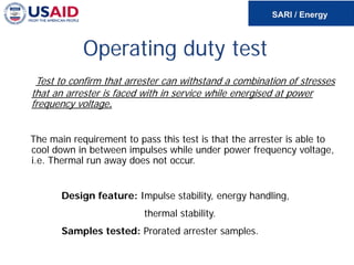
Long Duration Currenttest sequence
Example test for 5kA arrester:
Check reference voltage
Inject 18 impulses of “200A(min), 2ms duration”
Verify Uref is within 5% of original value
43.
Operating duty test
Testto confirm that arrester can withstand a combination of stresses
that an arrester is faced with in service while energised at power
frequency voltage.
The main requirement to pass this test is that the arrester is able to
cool down in between impulses while under power frequency voltage,
i.e. Thermal run away does not occur.
Design feature: Impulse stability, energy handling,
thermal stability.
Samples tested: Prorated arrester samples.
44.
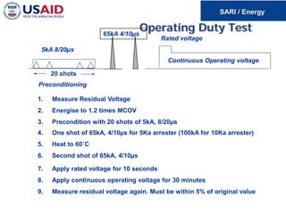
Operating Duty Test
20shots
Preconditioning
5kA 8/20µs
Rated voltage
Continuous Operating voltage
65kA 4/10µs
1. Measure Residual Voltage
2. Energise to 1.2 times MCOV
3. Precondition with 20 shots of 5kA, 8/20µs
4. One shot of 65kA, 4/10µs for 5Ka arrester (100kA for 10Ka arrester)
5. Heat to 60˚C
6. Second shot of 65kA, 4/10µs
7. Apply rated voltage for 10 seconds
8. Apply continuous operating voltage for 30 minutes
9. Measure residual voltage again. Must be within 5% of original value
45.
Revision of Standard
IEC60099-4,
2006
finally caught up
with
State-of-the-Art
Surge Arrester
Technology
46.
New Requirements
Moisture IngressTest;
Weather Ageing Tests;
(Tracking & Erosion Performance
of Housing)
Short Circuit Tests
(Test procedure still informative but commonly accepted with
distribution type arresters, more realistic failure simulation)
Routine testing: PD < 10pC,
Aging addressed.
47.
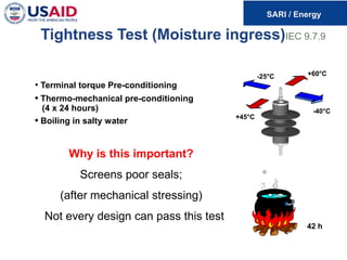
Tightness Test (Moistureingress)IEC 9.7.9
• Terminal torque Pre-conditioning
• Thermo-mechanical pre-conditioning
(4 x 24 hours)
• Boiling in salty water
Why is this important?
Screens poor seals;
(after mechanical stressing)
Not every design can pass this test
-25°C +60°C
+45°C
-40°C
42 h
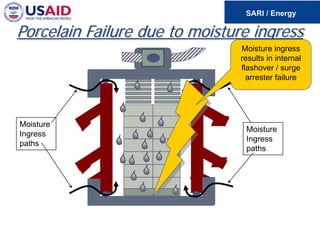
48.
Moisture Ingress Test
•Mechanical changes to be reported
• Increase of power loss < 20%
• Partial discharges not exceeding 10pC
• Change of residual voltage @
nom. discharge current not exceeding 5%
• No breakdown visible in voltage and current
oscillograms
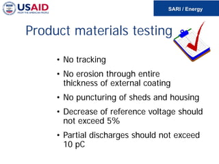
• No tracking
•No erosion through entire
thickness of external coating
• No puncturing of sheds and housing
• Decrease of reference voltage should
not exceed 5%
• Partial discharges should not exceed
10 pC
Product materials testing
52.
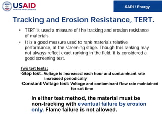
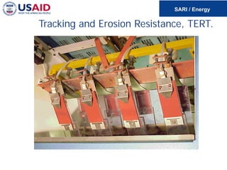
Tracking and ErosionResistance, TERT.
• TERT is used a measure of the tracking and erosion resistance
of materials.
• It is a good measure used to rank materials relative
performance, at the screening stage. Though this ranking may
not always reflect exact ranking in the field, it is considered a
good screening test.
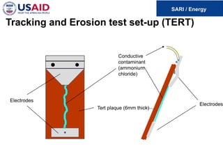
Two tert tests;
-Step test: Voltage is increased each hour and contaminant rate
increased periodically
-Constant Voltage test: Voltage and contaminant flow rate maintained
for set time
In either test method, the material must be
non-tracking with eventual failure by erosion
only. Flame failure is not allowed.
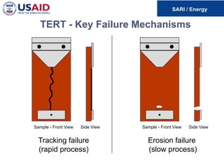
TERT - KeyFailure Mechanisms
Tracking failure
(rapid process)
Erosion failure
(slow process)
Sample - Front View Side View Sample - Front View Side View
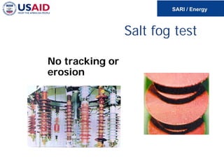
56.
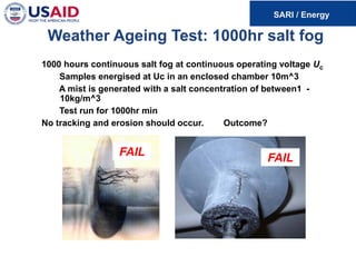
1000 hours continuoussalt fog at continuous operating voltage Uc
Samples energised at Uc in an enclosed chamber 10m^3
A mist is generated with a salt concentration of between1 -
10kg/m^3
Test run for 1000hr min
No tracking and erosion should occur. Outcome?
FAIL
FAIL
Weather Ageing Test: 1000hr salt fog
57.
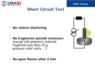
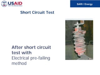
Short Circuit Test
•No violent shattering
• No fragments outside enclosure
(except soft polymeric material,
fragments less than 10 g,
pressure relief vents, ...)
• No open flames after 2 min
Specific Advantages ofPolymeric
Housing
• No internal air space, no chance of moisture ingress.
• Vandal proof.
• Non-explosive failure mode.
• High thermal conductivity. Rapid heat dissipation.
• Low weight and small size.
• Suitable for pollution environment.
• Resistant to transport damage and careless handling.
• Stud, pedestal or bracket mounted.
• Good for abnormal service conditions like enhanced external
insulation where operation is under high or low temperature or
altitudes over 1000m etc
• Easy to install.
61.
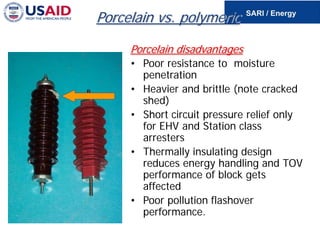
Porcelain vs. polymeric
Porcelaindisadvantages
• Poor resistance to moisture
penetration
• Heavier and brittle (note cracked
shed)
• Short circuit pressure relief only
for EHV and Station class
arresters
• Thermally insulating design
reduces energy handling and TOV
performance of block gets
affected
• Poor pollution flashover
performance.
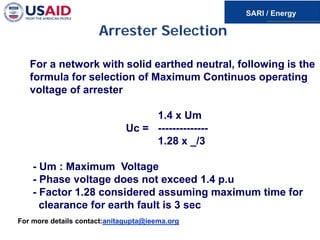
Arrester Selection
For anetwork with solid earthed neutral, following is the
formula for selection of Maximum Continuos operating
voltage of arrester
1.4 x Um
Uc = --------------
1.28 x _/3
- Um : Maximum Voltage
- Phase voltage does not exceed 1.4 p.u
- Factor 1.28 considered assuming maximum time for
clearance for earth fault is 3 sec
For more details contact:anitagupta@ieema.org