IIT Kharagpur
Advance TechnologyDevelopment Center
Study of EV Reference Model Simulation
Presented By
Mohd Ali Shamsi (24AT62R02)
Himanshu Sinha ( 24AT62R06)
Abhishek Saini (24AT62R07)
Muhammed Shabin (24AT62R08)
Submitted as for fulfillment of
Assignment of PADC
2.
INDEX
• Study ofEV Reference Model Simulation
• Environment Subsystem
• Longitudinal Driver
• Controller
• Vehicle Control Unit
• Battery Management System
• Vehicle Model
• Simulation results
3.
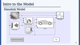
Intro to theModel
What is it for ?
This a full EV simulation model which is used for
a) Powertrain Matching Analysis
b) Control and Diagnostic algorithm design
c) HIL Testing
1
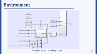
Environment
Description
The environment subsystemcreates environment variables, including
road grade, wind velocity and atmospheric temperature and pressure.
Role of Environment –
• Resistive forces on the vehicle are dependent on the air speed (drag force), gradient, as well as the road
conditions (rolling resistance).
• The performance of the engine (for Hybrid Vehicles) and the thermal control system is dependent on the
atmospheric temperature and pressure.
2
Scenarios
2
Description
The Scenarios blockimplements the Drive Cycle Source block to generate
a standard longitudinal drive cycle. Along with that, it allows for the input
of external driver reference and/or command signals.
Drive Cycle Source –
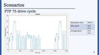
The drive cycle creates a standardized reference signal of speed and acceleration of
the vehicle over time. Its major objective is to stimulate real world driving patterns
for the testing of the vehicles. This helps in tuning the vehicle to optimize
performance.
Driver
2
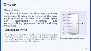
Description
This block generatesthe drive cycle tracking
commands. It takes the reference of the drive
cycle and takes the feedback vehicle speed
and environment condition and
correspondingly generates the vehicle driving
commands.
Longitudinal Driver
The Longitudinal Driver block implements a longitudinal speed-
tracking controller. Based on reference and feedback velocities,
the block generates normalized acceleration and braking
commands that can vary from 0 through 1.
Commands to the longitudinal driver
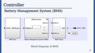
Controller
Description
The Controller blockcontain several modules like BMS,
VCU, Braking Controller etc.
This block generates the control signal to get the desired
output from the vehicle/plant.
2
12.
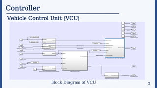
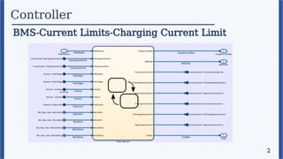
Controller
Vehicle Control Unit(VCU) - Controls the power train of the vehicle
2
Major Functions
• Receives the traction/braking commands from the pedals
• Uses BMS data to estimate the limiting current
• Receives machine speed and vehicle feedback
• Calculates required torque for driving/regenerative braking
• Calculates the mechanical braking to be applied at the wheels
Depending on the vehicle components this subsystem changes as well
Requirements in this model-
• To take in account of the Battery management system
• Provide torque command for the DC-DC converter to drive the
single motor driving the front axle
Controller
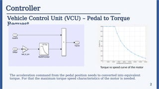
Vehicle Control Unit(VCU) – Pedal to Torque
Request
2
The acceleration command from the pedal position needs to converted into equivalent
torque. For that the maximum torque speed characteristics of the motor is needed.
Torque vs speed curve of the motor
15.
Controller
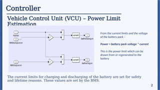
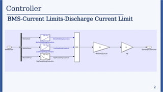
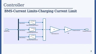
Vehicle Control Unit(VCU) – Power Limit
Estimation
2
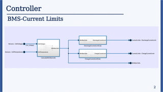
The current limits for charging and discharging of the battery are set for safety
and lifetime reasons. These values are set by the BMS.
From the current limits and the voltage
of the battery pack –
Power = battery pack voltage * current
This is the power limit which can be
drawn from or regenerated to the
battery
16.
Controller
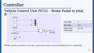
Vehicle Control Unit(VCU) – Brake Pedal to total
Braking
2
Brake pedal position is to be converted into actual braking force required.
Front Bias 1
Rear Bias 0.6
Brake Press
Factor Gain
8 * 106
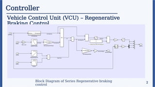
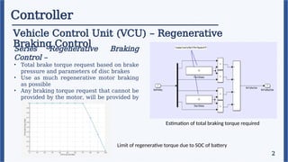
Controller
Vehicle Control Unit(VCU) – Regenerative
Braking Control
2
Series Regenerative Braking
Control –
• Total brake torque request based on brake
pressure and parameters of disc brakes
• Use as much regenerative motor braking
as possible
• Any braking torque request that cannot be
provided by the motor, will be provided by
the friction brakes
Estimation of total braking torque required
Limit of regenerative torque due to SOC of battery
19.
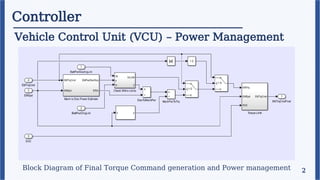
Controller
Vehicle Control Unit(VCU) – Power Management
2
Block Diagram of Final Torque Command generation and Power management
20.
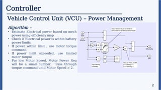
Controller
Vehicle Control Unit(VCU) – Power Management
2
Algorithm –
• Estimate Electrical power based on mech
power using efficiency map
• Check if Electrical power is within battery
power limits
• If power within limit , use motor torque
command
• If power limit exceeded, use limited
motor torque
• For low Motor Speed, Motor Power Req
will be a small number. Pass through
torque command until Motor Speed > 2.
Controller
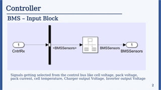
BMS – InputBlock
2
Signals getting selected from the control bus like cell voltage, pack voltage,
pack current, cell temperature, Charger output Voltage, Inverter output Voltage
23.
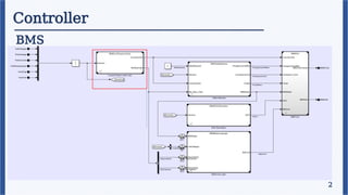
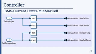
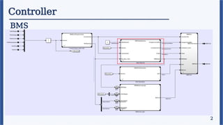
Controller
BMS
2
Signals getting selectedfrom the control bus like cell voltage, pack voltage,
pack current, cell temperature, Charger output Voltage, Inverter output Voltage
Controller
BMS
2
Signals getting selectedfrom the control bus like cell voltage, pack voltage,
pack current, cell temperature, Charger output Voltage, Inverter output Voltage