Download to read offline


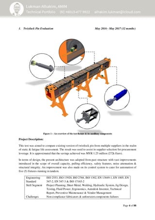


The document is a comprehensive technical portfolio detailing various engineering projects and evaluations related to mechanical systems, particularly focusing on hydraulic power units and twistlock pins. It includes project descriptions, methodologies, design improvements, testing results, and challenges encountered throughout the project timelines. Key highlights include significant cost savings, enhancements in safety and efficiency, and collaborations with external organizations for testing and validation.


