This document provides details of structural engineering drawings for various structural elements including:
1. Cross sections and reinforcement details of singly and doubly reinforced concrete beams with dimensions and reinforcement specifications.
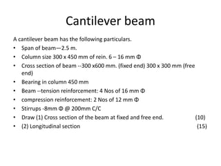
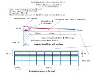
2. Cross sections and reinforcement details of a cantilever beam and lintel beam with dimensions and reinforcement specifications.
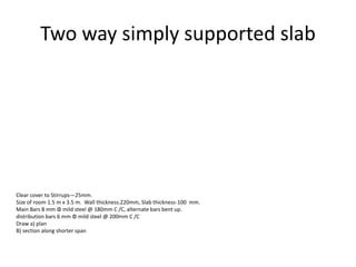
3. Plans and sections of a one-way simply supported slab and reinforcement details.
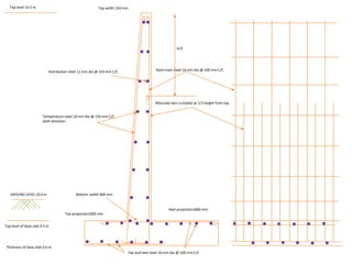
4. Foundation details, cross sections and plans of a water tank sluice with tower head.
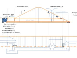
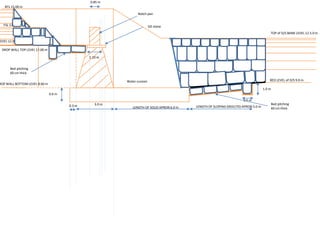
5. Cross sections and plans of an earthen dam with cutoff wall and apron details.
6. Layout and details of a septic tank and soak pit.
7. Cross section