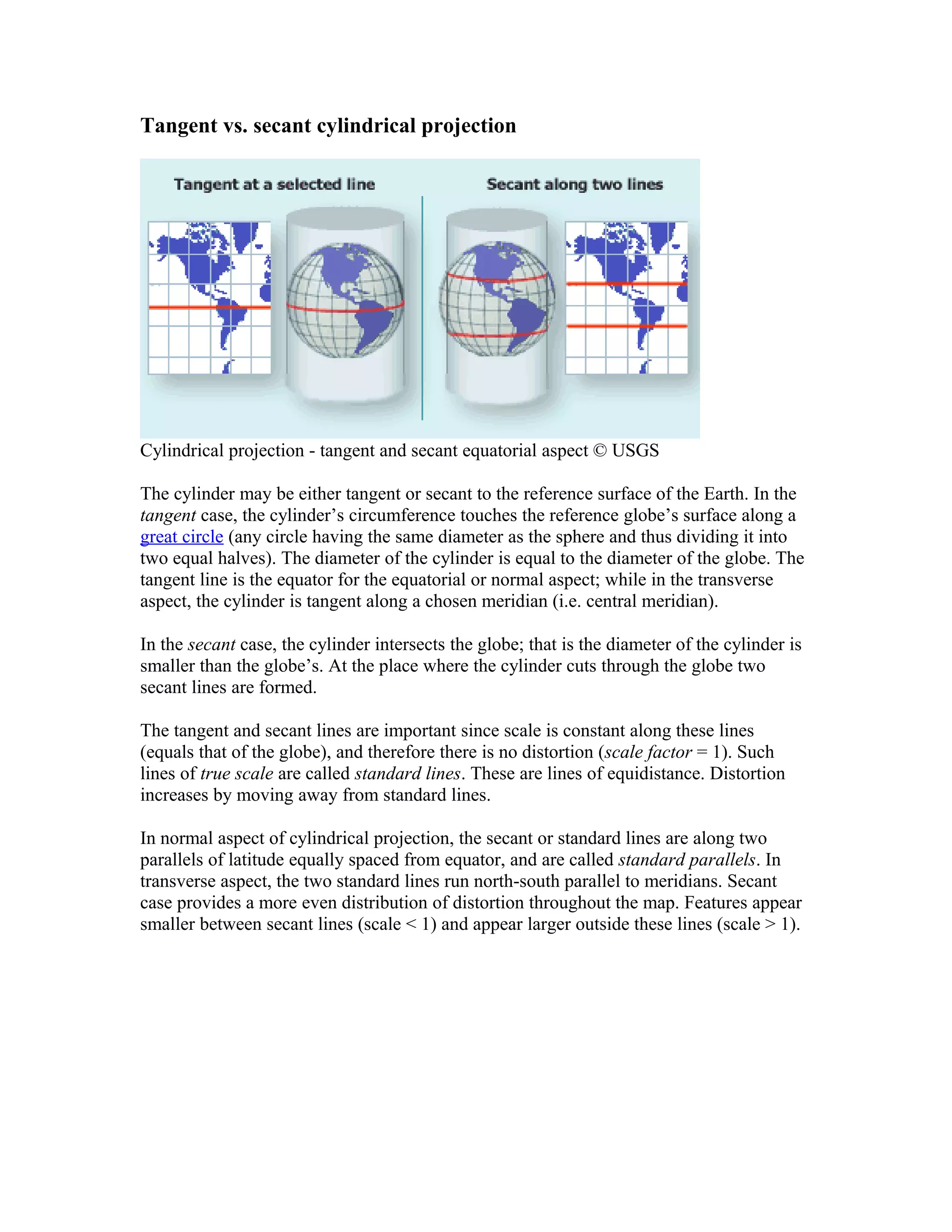
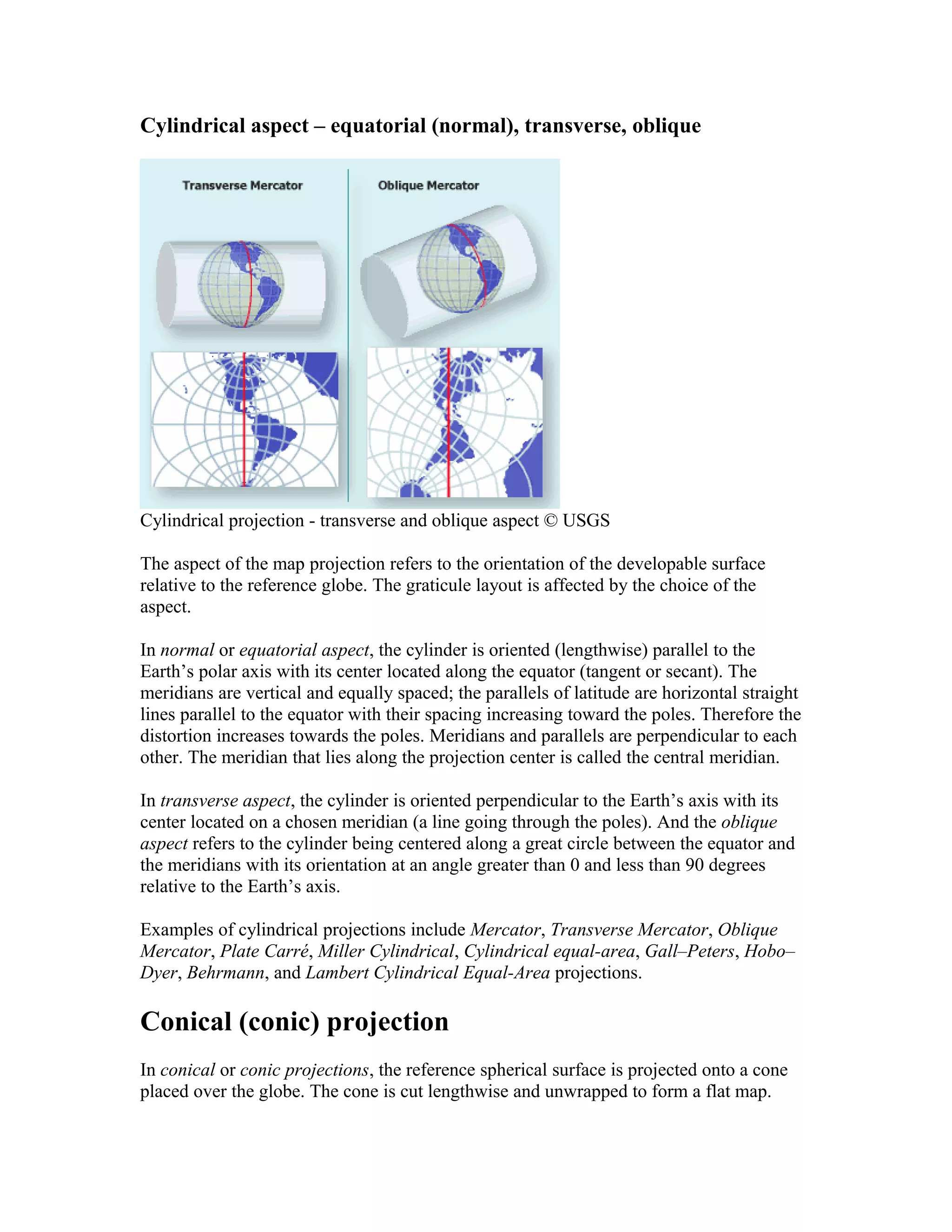
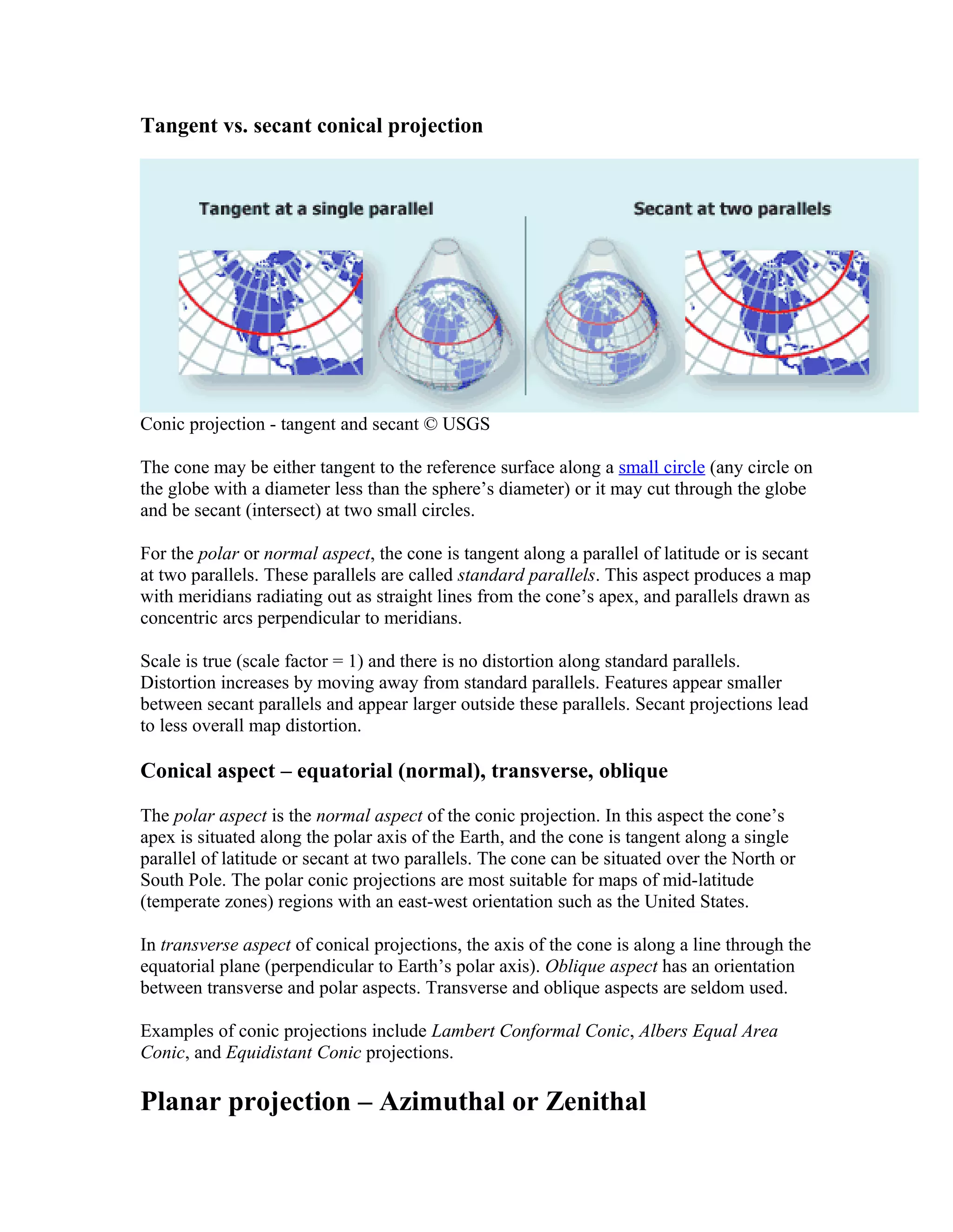
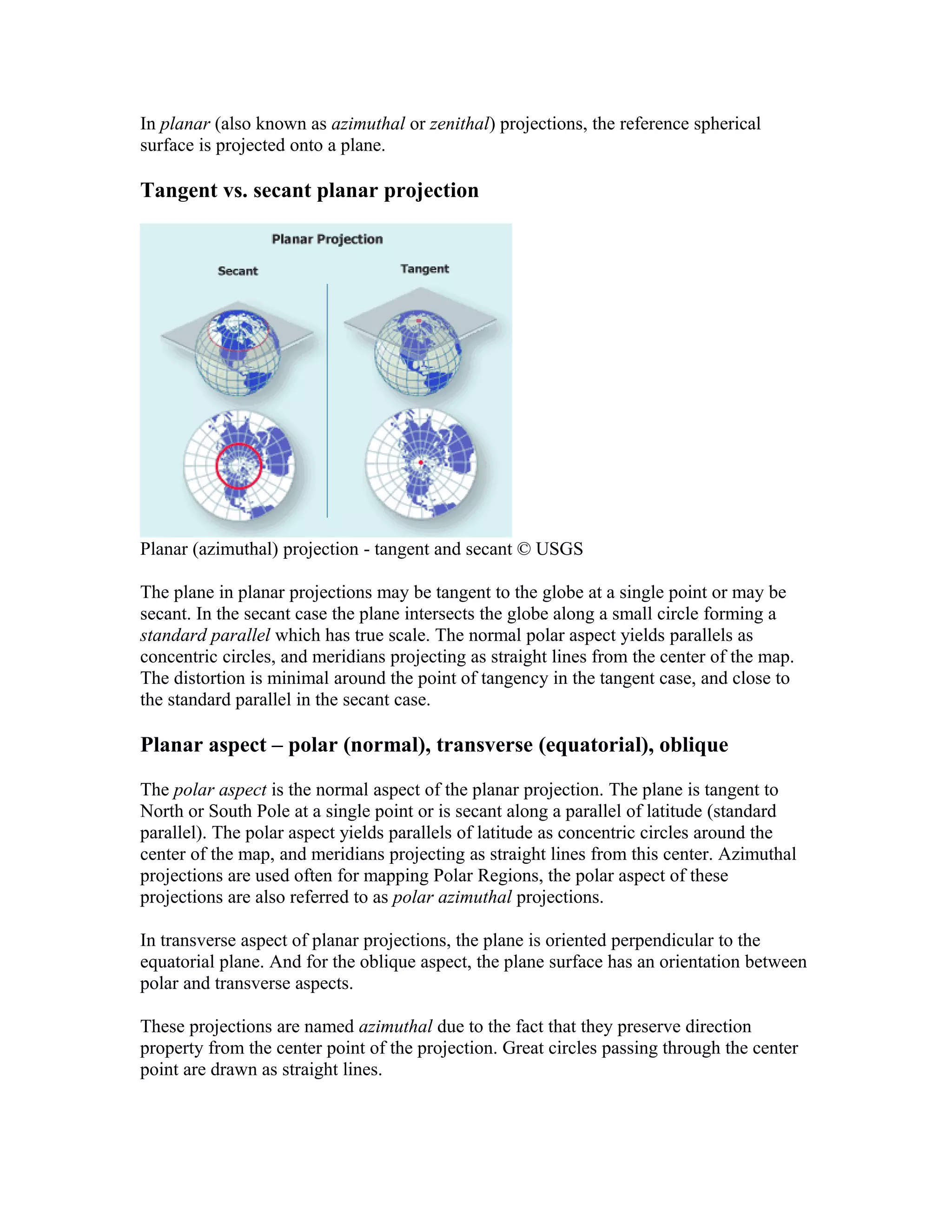
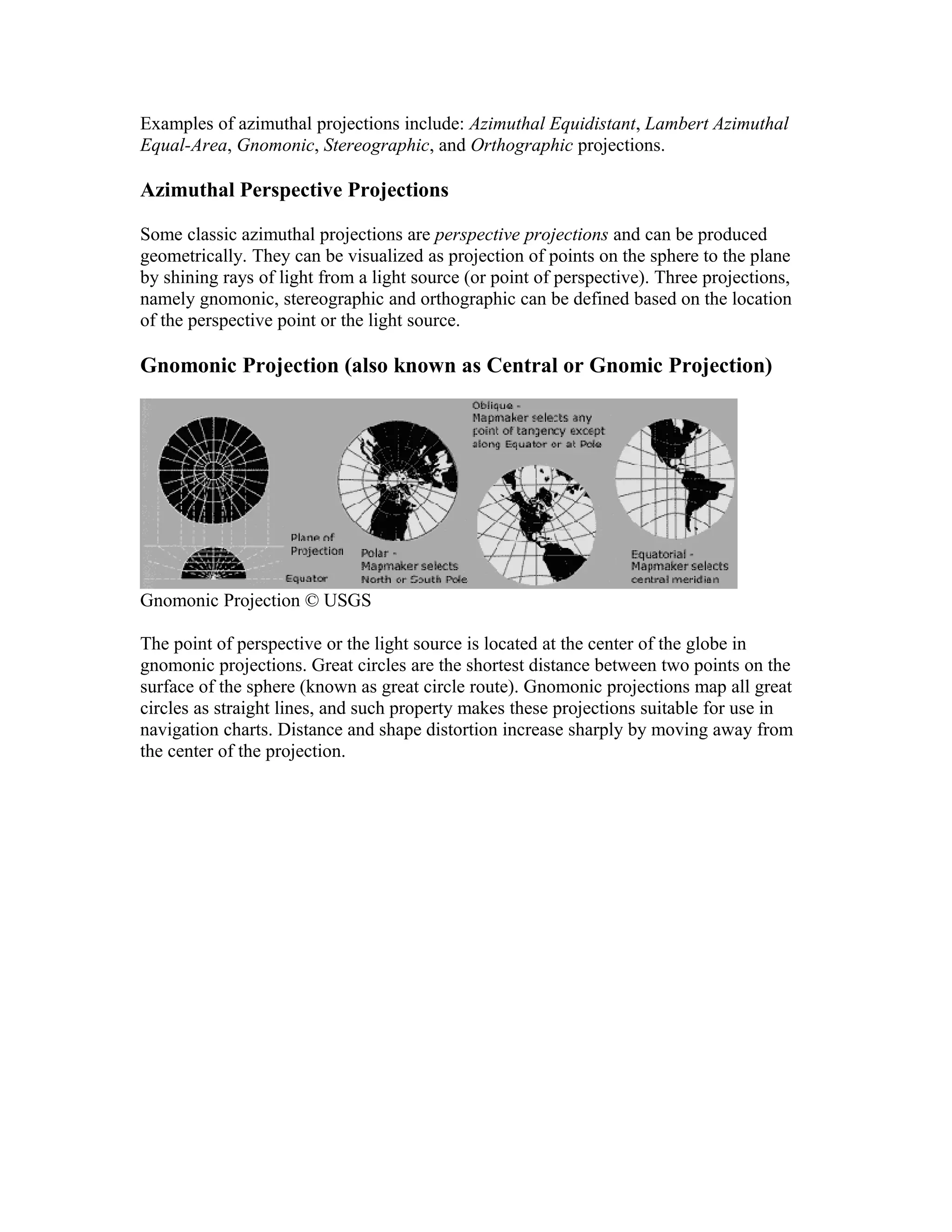
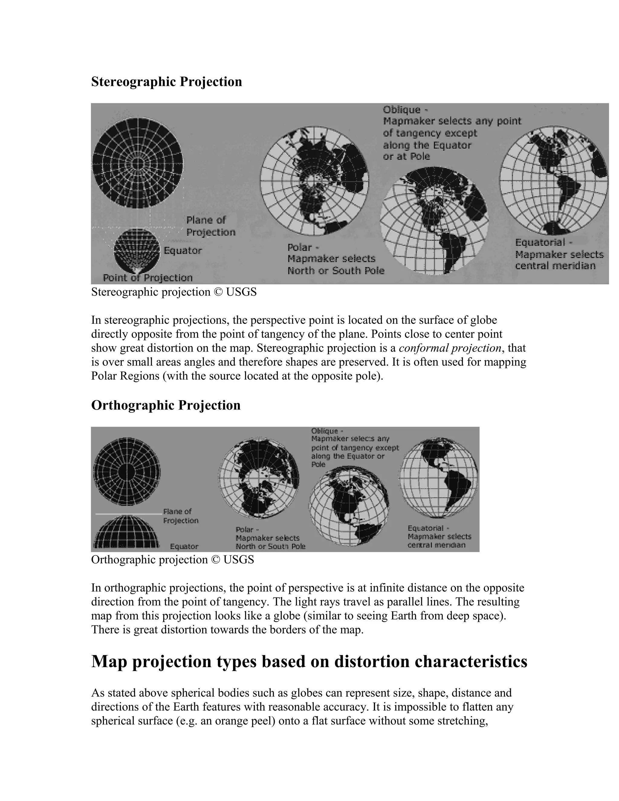
SlideShare a Scribd company logo
1 of 35
Statistical Techniques in Geographical 
Analysis 
By Damon Verial, eHow Contributor 
· 
· 
· Share 
· 
· Print this article 
Geographical analysis is the application of analytical techniques to geographical data. 
Much of the results in this field would not be possible without the strong statistical 
techniques that support the analysis of data. Geographical analysts rely on many 
statistical techniques, including probabilistic methods, hypothesis testing, sample 
selection and statistical inference, to perform analyses that allow for the results in this 
field. 
Other People Are Reading 
· How to Select a Data Analysis Technique 
· Techniques of Statistical Analysis 
1. Probability 
o Probability is a useful tool in geographical analysis, especially in 
situations where hard data does not exist. The application of probability 
can allow a geographical analyst to make reasonable predictions in these 
situations. Consider the lack of data regarding how people in the United 
States migrate and change residences. A geographical analyst can use the 
probabilities of moving certain distances along with the probabilities of 
moving certain directions to predict the average migration patterns of 
citizens of the United States. 
Hypotheses Tests 
o In geographical analysis, analysts often want to make meaningful 
comparisons. However, whether the data be air pollution levels in big 
cities or state population growth, simply looking at the data to determine if 
there are differences present is poor method to make this determination.
Statistics offers geographical analysts the ability to use hypotheses tests to 
conclude with high probability whether differences are present and in what 
ways the things being compared differ. 
o 
Data Selection 
o Geographical analysis relies heavily on finding data sets with which to 
perform analyses; yet the choice of data is a complicated procedure. To 
avoid collecting a biased data set, geographical analysts must employ a 
suitable sampling method for the situation. How to appropriately select a 
sample is a well-researched topic of statistics, and geographical analysts 
make heavy use of the well-founded statistical practice of selecting 
unbiased, representative samples. 
Inference 
o Often, geographical analysts perform analysis on a small geographical 
area because of restrictions in funding, time or other resources. In spite of 
this, analysts execute their analyses with the overall goal of making 
inferences about larger geographical areas. The problem is that without the 
appropriate statistical techniques these inferences will not hold. Statistics 
inference allows analysts to move away from simply describing their 
sample and move toward using their results to make larger, more general 
conclusions. 
http://www.ehow.com/info_8074582_statistical-techniques-geographical-analysis.html 
http://education.nationalgeographic.com/education/geographic-skills/?ar_a=1 
What is Cartography? 
Cartography Career 
Gis Cartography 
Cartography Program 
Cartography Jobs 
Computer Cartography 
Digital Cartography 
Cartography Services
A time zone map. 
Watch the Did-You-Know slideshow 
Article Details 
· Written By: S.E. Smith 
· Edited By: Bronwyn Harris 
· Copyright Protected: 
2003-2013 Conjecture Corporation 
· 
Print this Article 
Free Widgets for your Site/Blog 
Did You Know? 
US cell phone users send an average of 700 texts a month, but those age 18-24 send an 
average of 3,200 per month. more... 
get widget 
This Day in History 
June 15 , 1995 : The gloves didn't fit O.J. Simpson. more... 
get widget 
Subscribe to wiseGEEK 
Learn something new every day More Info... by email 
enter email ad 
Cartography is the art and science of map making, practiced by cartographers. Humans 
have been drawing maps for thousands of years, as part of an effort to understand their 
environment. The quest for an accurate map drove explorers to adventure to far-flung 
areas well into the 1700s, and cartographers in the modern day find frequent employment 
still, thanks to constant political and geological changes around the world. To train in 
cartography, a student should be prepared to take years of courses in multiple disciplines. 
The term comes from two Greek words, chartis, meaning map, and graphos, meaning to 
draw or write. In historic times, an individual cartographer hand drew a map in entirety, 
often with limited information. Modern practitioners of cartography have the advantage 
of computers and other equipment to assist them, making their maps more precise. The 
science of cartography has also evolved, as many maps have become multimedia data 
explosions, chock full of information for the reader.
Basic cartography covers two data components. The first is location data, indicating 
where the area being depicted is located. In ancient maps, location data often showed 
where something was in relation to something else, but modern maps usually use 
geographical coordinates such as latitude and longitude to orient their features. The 
second type of data is attributional data, showing bodies of water, mountains, valleys, 
hills, and other geographical features of interest and of note. 
Ads by Google 
MasterCard Locations 
API 
ATM, PayPass, rePower & prepaid locations for your apps & 
websites. 
developer.mastercard.com 
African Real Estate Data Information for investors Kenya and East Africa 
www.fusioncapitalafrica.com 
GeoEye1 & IKONOS 
Imagery 
0.5m GeoEye-I & 1m IKONOS imagery Discounted prices and 
fast service 
www.MapMart.com 
Is Jesus Really God? 
Discover the Evidence From Scholars About Jesus' Claims to 
be God 
Y-Jesus.com 
Under US$1000 Used 
cars. 
Japanese Cars for Sale. Various Japanese used cars here. 
www.tradecarview.com 
A map of the world reflects an immense mathematical and aesthetic challenge, that of 
translating the globe to a two dimensional surface. Many cartographers have struggled 
with this issue over the centuries, striving to project the features of the globe accurately 
and effectively. Numerous approaches have been taken to solve this problem, including 
the Mercator Projection, a map which distorts geological features north and south of the 
Equator in order to fit the globe into a neat rectangle. Other maps portray the globe in 
sections, reducing the amount of distortion necessary. 
The skills needed for cartography are immense. Cartography relies heavily on math to 
represent the Earth, along with science to help describe and understand geological 
features. Specialized maps may include things like ocean soundings, which requires a 
knowledge of oceanography, or unique rock formations, which implies geological study 
of the region. Knowledge of ongoing political events is also important, as nations divide, 
change names, or disappear more frequently than many people realize. 
The products of cartography can be divided into two rough types of map, although they 
may frequently overlap. A topographical map is one which is designed to be true to the 
landscape that it is depicting. Topographical maps usually include elevations, major 
geographical features, and other information which someone who use to orient him or 
herself. These maps can often be used for decades, unless a major geological event such 
as a volcanic eruption or earthquake occurs. 
A topological map, on the other hand, is used for conveying information such as highway 
routes, dangerous regions of a country, or population density. Topological maps can
sometimes be quite complex, showing multiple important features to readers to highlight 
and educate, and they change frequently as the lives of the people and places depicted on 
them change. 
http://www.wisegeek.com/what-is-cartography.htm 
Home Resources Careers 
Digital Pamphlet 
Careers in Cartography 
What Are the Cartographic Sciences ?
The cartographic sciences are geodesy, surveying, photogrammetry, remote sensing, 
geographic information systems (GIS), global positioning systems (GPS) and, of course, 
mathematics and statistics. In recent years, multimedia and virtual reality became part of 
the cartographic experience. These are all separate, though somewhat overlapping, 
disciplines, and they share an intimate relationship with cartography; indeed some have 
their own cartographic components. A working acquaintance with these fields is an 
essential part of the education of the modern cartographer. 
Geodesy 
Geodesy is a very specialized science concerned with determining the shape and size (the 
'figure') of the earth--not the solid earth, but the geoid, the surface defined by mean sea 
level--and establishing a framework of points whose locations are known very precisely 
in terms of latitude and longitude. This is achieved in two ways, by studying the earth's 
gravitational field and by conducting very high-accuracy surveying operations. At one 
time, such work was entirely ground-based, but satellite observations are now routine. 
Geodesy plays a fundamental role in cartography, for in order to map the earth, it is 
obviously necessary to know how big and what shape it is and to have reference points of 
known locations on its surface. 
Surveying 
If geodesy is unfamiliar to most people, surveying is quite the opposite, for almost 
everyone has seen the surveyor at work on city streets with transit, level or distance 
meter. There are many branches of surveying, including engineering surveys (carried out 
in connection with construction projects), cadastral surveys (concerned with property 
boundaries), hydrographic surveys (depicting water bodies) and mine surveys (outlining 
what is underground). The relation between surveying and cartography is very close 
indeed, and the end-product of the surveyor's work is often a map of some sort. One 
branch of surveying--topographic surveying-- has the production of maps as its express 
aim. Surveying, like cartography, has undergone major changes in recent years, but none 
so dramatic as those being brought about by Global Positioning Systems (GPS). 
Global Positioning Systems (GPS) 
A constellation of twenty-four satellites operated by the U.S. Department of Defense 
comprises GPS. It enables surveyors to determine ground locations very precisely at the 
click of a button on a hand-held receiver under any weather condition. GPS is 
revolutionizing the practice of surveying at a very fast pace. Today, a position on the 
earth's surface can be determined within fractions of a centimeter. The standard piece of 
information provided by a GPS receiver is a readout of the calculated latitude and 
longitude of a given position. These latitude and longitude positions obtained from a GPS 
can be plotted on a chart or on a map. 
Photogrammetry
Photogrammetry means literally measurement with light and has as its principal aim the 
production of topographic maps from aerial photographs. An earlier technological change 
that revolutionized topographic surveying, photogrammetry emerged in the 1930s. 
Previously topographic maps (large-scale maps in sheet form showing natural and 
cultural features in the landscape) were produced by traditional ground surveying 
methods, and while ground surveys are still needed, most of the detail on these maps--the 
rivers, coastlines, roads, buildings, contours, and so on--is now derived from airphotos. 
The work is done by the operator of a photogrammetric plotter, a complex piece of 
machinery that enables one to trace landscape features from a three-dimensional 'model' 
of the earth's surface created by viewing airphotos stereoscopically. In modern 
photogrammetry, the movements of the tracing device, or 'floating mark,' are translated 
directly into digital form and the map is plotted automatically. 
Remote Sensing 
A more recent discipline, dating from the 1960s, is remote sensing, the process of 
obtaining information about the earth's surface using sensors carried in aircraft and 
satellites. Though the discipline is new, the original form of remote sensing--aerial 
photography--dates from the nineteenth century, and techniques of airphoto interpretation 
have long been highly developed. All types of remote sensing involve the measurement 
of electromagnetic energy reflected from or radiated by the earth's surface, and 
photographic cameras (based on visible light) are now accompanied by other sensing 
devices operating at longer wavelengths. Examples are thermal scanners in the infrared 
waveband and radar systems in the microwaves. The information obtained may be in 
image form (like a photograph) or in digital form, and one of the most intriguing 
applications of remote sensing is the computer processing of digital multispectral data 
(data obtained simultaneously in more than one waveband) to produce land cover maps 
of the earth's surface. Another application of increasing importance is image mapping, 
the incorporation of a remote sensing image, enhanced by computer processing, into the 
map itself. Remote sensing, especially sensing from space, is a major source of mappable 
data, and as such plays a key role in modern cartography. 
Geographical Information Systems (GIS) 
Another new discipline, perhaps the most exciting of all, GIS is a computer-based system 
for handling geographical data, that is, data relating to the earth's surface. The word 
'handling' conceals a wealth of different operations, however. Some, like data storage and 
retrieval, are fairly mundane, but others, especially analytical operations like buffering, 
overlay, network analysis and viewshed modelling, are truly staggering in their potential 
for solving real-world problems. Maps are integral to a GIS. Data are stored in the 
computer in the form of 'layers,' each in effect a digital map of some component of the 
landscape (e.g. a streams layer, a roads layer, a soils layer) and analyses are achieved by 
performing operations on these layers, sometimes one at a time, sometimes on several 
layers simultaneously. Each stage in an analysis is displayed in map form on a high-resolution 
computer monitor, and the end-product is very commonly itself a map. GIS 
has become a billion-dollar business since the early eighties, which is not surprising 
given the range of proven applications. These include forest management, urban
planning, emergency vehicle dispatch, mineral prospecting, retail outlet location, 
maintenance of public utilities, and waging war, as well as a host of applications with 
purely scientific ends. 
Mathematics and Statistics 
Mathematics and statistics are heavily involved in the mapping process, not only because 
of the geometric aspects of describing locations in space, but also because of clear needs 
to describe and summarize the characteristics of spatial data. Through creative 
mathematical approaches, cartographers may find new solutions to solve spatial 
problems. 
Multimedia (MM) 
Computer systems allow for integrated access to a range of data through the means of 
stimulation of human senses using digital technology. This includes the integration of 
images, video and graphics, maps and photographs, text and sound and perhaps in the 
future smell and taste. This technology has a wide range of applications including 
education, scientific research, military activities and, of course, entertainment. 
Virtual Reality (VR) 
A computer system that is able to combine a mixture of real world experiences and 
computer generated material to allow for simulated real world representation produces a 
"virtual reality." VR addresses the construction of artificial worlds with clear spatial 
dimensions. The movie "Twister" is an excellent example how VR works. These same 
kind of images can be very useful for the scientist to model or demonstrate an event such 
as a natural hazard. Cartographers have a major role to play in the identification of VR as 
a potential research tool. 
Cartography and the cartographic sciences are all concerned in some way with data 
relating to the earth's surface, whether it be data acquisition, management, analysis or 
display, and there is a growing trend, driven by a common dependence on computer 
technology, for the disciplines described here to move even closer together. Reflecting 
this trend, the term geomatics is used in Canada to denote an integrated multi-disciplinary 
approach to dealing with earth-related data. In a sense, geomatics is an umbrella term for 
cartography and the cartographic sciences. 
http://www.cca-acc.org/careers-2.asp 
Types of Maps: 
Projections Geography Glossary Geography Label Me Printouts
A map is a representation of a place. There are many different types of maps 
that have different uses. 
Projections: Maps are called projections because map-makers have to project a 
3-D surface onto a 2-D map. A projection is a representation of one thing onto 
another, such as a curved 3-Dimensional surface (like the Earth) onto a flat 2- 
Dimensional map. There are 3 major types of projections: cylindrical, conic, 
and planar. 
Since a map is 2-dimensional representation of a 3-dimensional world, 
compromises must be made in accuracy (some information must be lost when 
one dimension is ignored). Different maps differ in the relative accuracy of the 
depiction of the area, the shapes of objects, actual distances, and compass 
direction. Maps that focus on maintaining one feature (like preserving distance) 
must distort other features (like area, shape and compass directions). 
Maps that accurately reflect area are often called equal-area maps (an example 
is the Albers equal-area conic map). Maps that maintain the shape of objects 
are called conformal. Maps that correctly show the distance between points are 
often called equi-distant maps (note that the shortest distance between two 
points on a map is generally not a straight line. but a curve). Navigational maps 
need accurate compass directions maintained on the map (like the Mercator 
map). 
Related Terms: 
central 
meridian 
A central meridian 
is a meridian that 
passes through the 
center of a 
projection. The 
central meridian is 
often a straight line 
that is an axis of 
symmetry of the 
projection. 
conic projection 
A conic projection is a 
type of map in which a 
cone is wrapped 
around a sphere (the 
globe), and the details 
of the globe are 
projected onto the 
cylindrical surface. 
Then, the cylinder is 
unwrapped into a flat 
cylindrical projection 
A cylindrical projection is a 
type of map in which a 
cylinder is wrapped around a 
sphere (the globe), and the 
details of the globe are 
projected onto the cylindrical 
surface. Then, the cylinder is 
unwrapped into a flat 
surface, yielding a 
rectangular-shaped map. 
Cylindrical maps have a lot 
equator 
The equator is 
an imaginary 
circle around 
the earth, 
halfway 
between the 
north and 
south poles.
surface. 
of distortion in the polar 
regions (that is, the size of 
the polar regions is greatly 
exaggerated on these maps). 
geographical 
coordinate 
system 
A geographical 
coordinate system 
is a system that 
uses latitude and 
longitude to 
describe points on 
the spherical 
surface of the 
globe. 
latitude 
Latitude is the 
angular distance 
north or south 
from the 
equator to a 
particular 
location. The 
equator has a 
latitude of zero 
degrees. The 
North Pole has a 
latitude of 90 
degrees North; 
the South Pole 
has a latitude of 
90 degrees 
South. 
longitude 
Longitude is the 
angular distance east 
or west from the 
north-south line that 
passes through 
Greenwich, England, 
to a particular 
location. Greenwich, 
England has a 
longitude of zero 
degrees. The farther 
east or west of 
Greenwich you are, 
the greater your 
longitude. Midway 
Islands (in the Pacific 
Ocean) have a 
longitude of 180 
degrees (they are on 
the opposite side of 
the globe from 
Greenwich). 
Mercator projection 
A Mercator projection is a 
type of rectangular map in 
which the true compass 
direction are kept intact (lines 
of latitude and longitude 
intersect at right angles), but 
areas are distorted (for 
example, polar areas look 
much larger than they really 
are). Mercator projections are 
useful for nautical 
navigation. Geradus 
Mercator devised this 
cylindrical projection for use 
in navigation in 1569. 
meridian 
A meridian a circular 
arc of longitude that 
meets at the north and 
south poles and 
connects all places of 
the same longitude. 
The prime meridian 
(0 degrees longitude) 
passes through 
Greenwich, England. 
Mollweide projection 
A Mollweide projection is a type of 
sinusoidal projection map in which 
the entire surface of the Earth is 
shown within an ellipse. Lines of 
latitude are parallel to the equator, but 
lines of longitude are curved in such a 
Orthographic 
projection 
An Orthographic projection 
is a type of map in which is 
essentially a drawing of 
(one side of) a globe. There 
is a lot of distortion of area 
in this type of map, but one 
gets the idea that the globe 
is being represented.
way that area distortion is minimal. 
The distortion is greatest at the edges 
of the ellipse. This type of projection 
was created by Carl B. Mollweide in 
1805. 
Orthophanic projection 
The Orthophanic (meaning 'right 
appearing') projection, also called the 
Robinson projection, is a widely-used 
type of map in which the Earth is shown 
in a flattened ellipse. In this 
pseudocylindrical. projection, lines of 
latitude are parallel to the equator, but 
lines of latitude are elliptical arcs. In a 
Robinson projection, area is represented 
accurately, but the distances and 
compass directions are distorted (for 
example, compass lines are curved). 
This type of projection was first made in 
1963 by Arthur H. Robinson. 
parallel 
A parallel (of 
latitude) is a line on 
a map that represents 
an imaginary east-west 
circle drawn on 
the Earth in a plane 
parallel to the plane 
that contains the 
equator. 
planar projection 
A planar projection is a 
type of map in which the 
details of the globe are 
projected onto a plane (a 
flat surface) yielding a 
rectangular-shaped map. 
Cylindrical maps have a 
lot of distortion towards 
the edges. 
Robinson projection 
The Robinson projection is a 
widely-used type of map in 
which the Earth is shown within 
an ellipse with a flat top and 
bottom. In this 
pseudocylindrical. projection, 
lines of latitude are parallel to 
the equator, but lines of latitude 
are elliptical arcs. In a Robinson 
projection, area is represented 
accurately, but the distances and 
compass directions are distorted 
(for example, compass lines are 
curved). This type of projection 
was first made in 1963 by 
Arthur H. Robinson; it is also 
called the Orthophanic 
projection (meaning 'right 
sinusoidal projection 
A sinusoidal projection is 
a type of map projection in 
which lines of latitude are 
parallel to the equator, and 
lines of longitude are 
curved around the prime 
meridian. 
Winkel Tripel 
projection 
A Winkel Tripel projection 
is a type of preudocylindrical 
projection map in which both 
the lines of latitude and 
longitude are curved. The 
Winkel Tripel projection was 
adopted by the National 
Geographic Society in the 
late 1990s (replacing the 
Robinson projection).
appearing'). 
http://www.enchantedlearning.com/geography/glossary/projections.shtml 
Search R2013 
· 
· Mapping Toolbox 
· .. . 
· Coordinate Systems 
· Projected Coordinate Systems 
· Projections and Parameters 
The Three Main Families of Map Projections 
On this page… 
Unwrapping the Sphere to a Plane 
Cylindrical Projections 
Conic Projections 
Azimuthal Projections 
Unwrapping the Sphere to a Plane 
Mapmakers have developed hundreds of map projections, over several thousand years. 
Three large families of map projection, plus several smaller ones, are generally 
acknowledged. These are based on the types of geometric shapes that are used to transfer 
features from a sphere or spheroid to a plane. As described above, map projections are 
based on developable surfaces, and the three traditional families consist of cylinders, 
cones, and planes. They are used to classify the majority of projections, including some 
that are not analytically (geometrically) constructed. In addition, a number of map 
projections are based on polyhedra. While polyhedral projections have interesting and 
useful properties, they are not described in this guide. 
Which developable surface to use for a projection depends on what region is to be 
mapped, its geographical extent, and the geometric properties that areas, boundaries, and 
routes need to have, given the purpose of the map. The following sections describe and 
illustrate how the cylindrical, conic, and azimuthal families of map projections are 
constructed and provides some examples of projections that are based on them. 
Cylindrical Projections
A cylindrical projection is produced by wrapping a cylinder around a globe representing 
the Earth. The map projection is the image of the globe projected onto the cylindrical 
surface, which is then unwrapped into a flat surface. When the cylinder aligns with the 
polar axis, parallels appear as horizontal lines and meridians as vertical lines. Cylindrical 
projections can be either equal-area, conformal, or equidistant. The following figure 
shows a regular cylindrical or normal aspect orientation in which the cylinder is tangent 
to the Earth along the Equator and the projection radiates horizontally from the axis of 
rotation. The projection method is diagrammed on the left, and an example is given on 
the right (equal-area cylindrical projection, normal/equatorial aspect). 
For a description of projection aspect, see Projection Aspect. 
Some widely used cylindrical map projections are 
· Equal-area cylindrical projection 
· Equidistant cylindrical projection 
· Mercator projection 
· Miller projection 
· Plate Carrée projection 
· Universal transverse Mercator projection 
Pseudocylindrical Map Projections 
All cylindrical projections fill a rectangular plane. Pseudocylindrical projection outlines 
tend to be barrel-shaped rather than rectangular. However, they do resemble cylindrical 
projections, with straight and parallel latitude lines, and can have equally spaced
meridians, but meridians are curves, not straight lines. Pseudocylindrical projections can 
be equal-area, but are not conformal or equidistant. 
Some widely-used pseudocylindrical map projections are 
· Eckert projections (I-VI) 
· Goode homolosine projection 
· Mollweide projection 
· Quartic authalic projection 
· Robinson projection 
· Sinusoidal projection 
Conic Projections 
A conic projection is derived from the projection of the globe onto a cone placed over it. 
For the normal aspect, the apex of the cone lies on the polar axis of the Earth. If the cone 
touches the Earth at just one particular parallel of latitude, it is called tangent. If made 
smaller, the cone will intersect the Earth twice, in which case it is called secant. Conic 
projections often achieve less distortion at mid- and high latitudes than cylindrical 
projections. A further elaboration is the polyconic projection, which deploys a family of 
tangent or secant cones to bracket a succession of bands of parallels to yield even less 
scale distortion. The following figure illustrates conic projection, diagramming its 
construction on the left, with an example on the right (Albers equal-area projection, polar 
aspect). 
Some widely-used conic projections are 
· Albers Equal-area projection
· Equidistant projection 
· Lambert conformal projection 
· Polyconic projection 
Azimuthal Projections 
An azimuthal projection is a projection of the globe onto a plane. In polar aspect, an 
azimuthal projection maps to a plane tangent to the Earth at one of the poles, with 
meridians projected as straight lines radiating from the pole, and parallels shown as 
complete circles centered at the pole. Azimuthal projections (especially the orthographic) 
can have equatorial or oblique aspects. The projection is centered on a point, that is either 
on the surface, at the center of the Earth, at the antipode, some distance beyond the Earth, 
or at infinity. Most azimuthal projections are not suitable for displaying the entire Earth 
in one view, but give a sense of the globe. The following figure illustrates azimuthal 
projection, diagramming it on the left, with an example on the right (orthographic 
projection, polar aspect). 
Some widely used azimuthal projections are 
· Equidistant azimuthal projection 
· Gnomonic projection 
· Lambert equal-area azimuthal projection 
· Orthographic projection 
· Stereographic projection
· Universal polar stereographic projection 
For additional information on families of map projections and specific map projections, 
see Supported Map Projections. 
http://www.mathworks.com/help/map/the-three-main-families-of-map-projections.html 
Cylindrical Projection 
A cylindrical projection map is the most common type of map that we see. Imagine 
placing the movie screen around the globe in a cylinder shape. The projection that results 
is depicted in this image. Notice that areas close to the equator have very little distortion. 
However, the closer to the poles that one travels, the more distorted the map becomes. In 
this example, Greenland appears to be many times larger than it really is. 
Conic Projection 
A conic projection map is created by placing a cone shaped screen on a globe. The 
resulting projection is more accurate than the cylindrical projection map discussed above. 
However, the further we travel down the map, the more distorted and less accurate the 
map becomes.
Plane Projection 
A plane projection is created by placing an imaginary screen directly above or below a 
globe. The image that would result is called a plane projection. This type of map 
projection is not commonly used.
Interrupted Projection 
There are many different types of interrupted projection maps. These types of maps try to 
depict the continents as accurately as possible by leaving blank space in the less 
important areas of the map, such as in the oceans.
Map Projections - types and distortion 
patterns 
The shape of the Earth is represented as a sphere. It is also modeled more accurately as an 
oblate spheroid or an ellipsoid. A globe is a scaled down model of the Earth. Although 
they can represent size, shape, distance and directions of the Earth features with 
reasonable accuracy, globes are not practical or suitable for many applications. They are 
hard to transport and store; for example you can not stuff a globe in your backpack while 
hiking or store it in your car’s glove compartment. Globes are not suitable for use at large 
scales, such as finding directions in a city or following a hiking route, where a more 
detailed image is essential. They are expensive to produce, especially in varying sizes 
(scales). On a curved surface, measuring terrain properties is difficult, and it is not 
possible to see large portions of the Earth at once. 
Maps do not suffer from the above shortcomings and are more practical than globes in 
most applications. Historically cartographers have tried to address the challenge of
representing the curved surface of the Earth on a map plane, and to this end have devised 
map projections. A map projection is the transformation of Earth’s curved surface (or a 
portion of) onto a two-dimensional flat surface by means of mathematical equations. 
During such transformation, the angular geographic coordinates (latitude, longitude) 
referencing positions on the surface of the Earth are converted to Cartesian coordinates 
(x, y) representing position of points on a flat map. 
Types of map projections based on developable surface 
One way of classifying map projections is by the type of the developable surface onto 
which the reference sphere is projected. A developable surface is a geometric shape that 
can be laid out into a flat surface without stretching or tearing. The three types of 
developable surfaces are cylinder, cone and plane, and their corresponding projections 
are called cylindrical, conical and planar. Projections can be further categorized based on 
their point(s) of contact (tangent or secant) with the reference surface of the Earth and 
their orientation (aspect). 
Keep in mind that while some projections use a geometric process, in reality most 
projections use mathematical equations to transform the coordinates from a globe to a flat 
surface. The resulting map plane in most instances can be rolled around the globe in the 
form of cylinder, cone or placed to the side of the globe in the case of the plane. The 
developable surface serves as a good illustrative analogy of the process of flattening out a 
spherical object onto a plane. 
Cylindrical projection 
In cylindrical projections, the reference spherical surface is projected onto a cylinder 
wrapped around the globe. The cylinder is then cut lengthwise and unwrapped to form a 
flat map.
Tangent vs. secant cylindrical projection 
Cylindrical projection - tangent and secant equatorial aspect © USGS 
The cylinder may be either tangent or secant to the reference surface of the Earth. In the 
tangent case, the cylinder’s circumference touches the reference globe’s surface along a 
great circle (any circle having the same diameter as the sphere and thus dividing it into 
two equal halves). The diameter of the cylinder is equal to the diameter of the globe. The 
tangent line is the equator for the equatorial or normal aspect; while in the transverse 
aspect, the cylinder is tangent along a chosen meridian (i.e. central meridian). 
In the secant case, the cylinder intersects the globe; that is the diameter of the cylinder is 
smaller than the globe’s. At the place where the cylinder cuts through the globe two 
secant lines are formed. 
The tangent and secant lines are important since scale is constant along these lines 
(equals that of the globe), and therefore there is no distortion (scale factor = 1). Such 
lines of true scale are called standard lines. These are lines of equidistance. Distortion 
increases by moving away from standard lines. 
In normal aspect of cylindrical projection, the secant or standard lines are along two 
parallels of latitude equally spaced from equator, and are called standard parallels. In 
transverse aspect, the two standard lines run north-south parallel to meridians. Secant 
case provides a more even distribution of distortion throughout the map. Features appear 
smaller between secant lines (scale < 1) and appear larger outside these lines (scale > 1).
Cylindrical aspect – equatorial (normal), transverse, oblique 
Cylindrical projection - transverse and oblique aspect © USGS 
The aspect of the map projection refers to the orientation of the developable surface 
relative to the reference globe. The graticule layout is affected by the choice of the 
aspect. 
In normal or equatorial aspect, the cylinder is oriented (lengthwise) parallel to the 
Earth’s polar axis with its center located along the equator (tangent or secant). The 
meridians are vertical and equally spaced; the parallels of latitude are horizontal straight 
lines parallel to the equator with their spacing increasing toward the poles. Therefore the 
distortion increases towards the poles. Meridians and parallels are perpendicular to each 
other. The meridian that lies along the projection center is called the central meridian. 
In transverse aspect, the cylinder is oriented perpendicular to the Earth’s axis with its 
center located on a chosen meridian (a line going through the poles). And the oblique 
aspect refers to the cylinder being centered along a great circle between the equator and 
the meridians with its orientation at an angle greater than 0 and less than 90 degrees 
relative to the Earth’s axis. 
Examples of cylindrical projections include Mercator, Transverse Mercator, Oblique 
Mercator, Plate Carré, Miller Cylindrical, Cylindrical equal-area, Gall–Peters, Hobo– 
Dyer, Behrmann, and Lambert Cylindrical Equal-Area projections. 
Conical (conic) projection 
In conical or conic projections, the reference spherical surface is projected onto a cone 
placed over the globe. The cone is cut lengthwise and unwrapped to form a flat map.
Tangent vs. secant conical projection 
Conic projection - tangent and secant © USGS 
The cone may be either tangent to the reference surface along a small circle (any circle on 
the globe with a diameter less than the sphere’s diameter) or it may cut through the globe 
and be secant (intersect) at two small circles. 
For the polar or normal aspect, the cone is tangent along a parallel of latitude or is secant 
at two parallels. These parallels are called standard parallels. This aspect produces a map 
with meridians radiating out as straight lines from the cone’s apex, and parallels drawn as 
concentric arcs perpendicular to meridians. 
Scale is true (scale factor = 1) and there is no distortion along standard parallels. 
Distortion increases by moving away from standard parallels. Features appear smaller 
between secant parallels and appear larger outside these parallels. Secant projections lead 
to less overall map distortion. 
Conical aspect – equatorial (normal), transverse, oblique 
The polar aspect is the normal aspect of the conic projection. In this aspect the cone’s 
apex is situated along the polar axis of the Earth, and the cone is tangent along a single 
parallel of latitude or secant at two parallels. The cone can be situated over the North or 
South Pole. The polar conic projections are most suitable for maps of mid-latitude 
(temperate zones) regions with an east-west orientation such as the United States. 
In transverse aspect of conical projections, the axis of the cone is along a line through the 
equatorial plane (perpendicular to Earth’s polar axis). Oblique aspect has an orientation 
between transverse and polar aspects. Transverse and oblique aspects are seldom used. 
Examples of conic projections include Lambert Conformal Conic, Albers Equal Area 
Conic, and Equidistant Conic projections. 
Planar projection – Azimuthal or Zenithal
In planar (also known as azimuthal or zenithal) projections, the reference spherical 
surface is projected onto a plane. 
Tangent vs. secant planar projection 
Planar (azimuthal) projection - tangent and secant © USGS 
The plane in planar projections may be tangent to the globe at a single point or may be 
secant. In the secant case the plane intersects the globe along a small circle forming a 
standard parallel which has true scale. The normal polar aspect yields parallels as 
concentric circles, and meridians projecting as straight lines from the center of the map. 
The distortion is minimal around the point of tangency in the tangent case, and close to 
the standard parallel in the secant case. 
Planar aspect – polar (normal), transverse (equatorial), oblique 
The polar aspect is the normal aspect of the planar projection. The plane is tangent to 
North or South Pole at a single point or is secant along a parallel of latitude (standard 
parallel). The polar aspect yields parallels of latitude as concentric circles around the 
center of the map, and meridians projecting as straight lines from this center. Azimuthal 
projections are used often for mapping Polar Regions, the polar aspect of these 
projections are also referred to as polar azimuthal projections. 
In transverse aspect of planar projections, the plane is oriented perpendicular to the 
equatorial plane. And for the oblique aspect, the plane surface has an orientation between 
polar and transverse aspects. 
These projections are named azimuthal due to the fact that they preserve direction 
property from the center point of the projection. Great circles passing through the center 
point are drawn as straight lines.
Examples of azimuthal projections include: Azimuthal Equidistant, Lambert Azimuthal 
Equal-Area, Gnomonic, Stereographic, and Orthographic projections. 
Azimuthal Perspective Projections 
Some classic azimuthal projections are perspective projections and can be produced 
geometrically. They can be visualized as projection of points on the sphere to the plane 
by shining rays of light from a light source (or point of perspective). Three projections, 
namely gnomonic, stereographic and orthographic can be defined based on the location 
of the perspective point or the light source. 
Gnomonic Projection (also known as Central or Gnomic Projection) 
Gnomonic Projection © USGS 
The point of perspective or the light source is located at the center of the globe in 
gnomonic projections. Great circles are the shortest distance between two points on the 
surface of the sphere (known as great circle route). Gnomonic projections map all great 
circles as straight lines, and such property makes these projections suitable for use in 
navigation charts. Distance and shape distortion increase sharply by moving away from 
the center of the projection.
Stereographic Projection 
Stereographic projection © USGS 
In stereographic projections, the perspective point is located on the surface of globe 
directly opposite from the point of tangency of the plane. Points close to center point 
show great distortion on the map. Stereographic projection is a conformal projection, that 
is over small areas angles and therefore shapes are preserved. It is often used for mapping 
Polar Regions (with the source located at the opposite pole). 
Orthographic Projection 
Orthographic projection © USGS 
In orthographic projections, the point of perspective is at infinite distance on the opposite 
direction from the point of tangency. The light rays travel as parallel lines. The resulting 
map from this projection looks like a globe (similar to seeing Earth from deep space). 
There is great distortion towards the borders of the map. 
Map projection types based on distortion characteristics 
As stated above spherical bodies such as globes can represent size, shape, distance and 
directions of the Earth features with reasonable accuracy. It is impossible to flatten any 
spherical surface (e.g. an orange peel) onto a flat surface without some stretching,
tearing, or shearing. Similarly, when trying to project a spherical surface of the Earth 
onto a map plane, the curved surface will get deformed, causing distortions in shape 
(angle), area, direction or distance of features. All projections cause distortions in varying 
degrees; there is no one perfect projection preserving all of the above properties, rather 
each projection is a compromise best suited for a particular purpose. 
Different projections are developed for different purposes. Some projections minimize 
distortion or preserve some properties at the expense of increasing distortion of others. 
The choice of a projection for a map depends on such factors as the purpose for which the 
map will be used, the area being mapped, and the map’s scale (distortion is more 
pronounced in small-scale mapping). 
Measuring map scale distortion – scale factor & 
principal (nominal) scale 
As mentioned above, a reference globe (reference surface of the Earth) is a scaled down 
model of the Earth. This scale can be measured as the ratio of distance on the globe to the 
corresponding distance on the Earth. Throughout the globe this scale is constant. For 
example, a 1:250000 representative fraction scale indicates that 1 unit (e.g. km) on the 
globe represents 250000 units on Earth. The principal scale or nominal scale of a flat 
map (the stated map scale) refers to this scale of its generating globe. 
However the projection of the curved surface on the plane and the resulting distortions 
from the deformation of the surface will result in variation of scale throughout a flat map. 
In other words the actual map scale is different for different locations on the map plane 
and it is impossible to have a constant scale throughout the map. This variation of scale 
can be visualized by Tissot's indicatrix explained in detail below. Measure of scale 
distortion on map plane can also be quantified by the use of scale factor. 
Scale factor is the ratio of actual scale at a location on map to the principal (nominal) 
map scale (SF = actual scale / nominal scale). This can be alternatively stated as ratio of 
distance on the map to the corresponding distance on the reference globe. A scale factor 
of 1 indicates actual scale is equal to nominal scale, or no scale distortion at that point on 
the map. Scale factors of less than or greater than one are indicative of scale distortion. 
The actual scale at a point on map can be obtained by multiplying the nominal map scale 
by the scale factor. 
As an example, the actual scale at a given point on map with scale factor of 0.99860 at 
the point and nominal map scale of 1:50000 is equal to (1:50000 x 0.99860) = (0.99860 / 
50000) = 1:50070 (which is a smaller scale than the nominal map scale). Scale factor of 2 
indicates that the actual map scale is twice the nominal scale; if the nominal scale is 
1:4million, then the map scale at the point would be (1:4million x 2) = 1:2million. A 
scale factor of 0.99950 at a given location on the map indicates that 999.5 meters on the 
map represents 1000 meters on the reference globe.
As mentioned above, there is no distortion along standard lines as evident in following 
figures. On a tangent surface to the reference globe, there is no scale distortion at the 
point (or along the line) of tangency and therefore scale factor is 1. Distortion increases 
with distance from the point (or line) of tangency. 
Map scale distortion of a tangent cylindrical projection - SF = 1 along line of tangency 
Scale distortion on a tangent surface to the globe 
On a secant surface to the reference globe, there is no distortion along the standard lines 
(lines of intersection) where SF = 1. Between the secant lines where the surface is inside 
the globe, features appear smaller than in reality and scale factor is less than 1. At places 
on map where the surface is outside the globe, features appear larger than in reality and 
scale factor is greater than 1. A map derived from a secant projection surface has less 
overall distortion than a map from a tangent surface. 
Map scale distortion of a secant cylindrical projection - SF = 1 along secant lines
Scale distortion on a secant surface to the globe 
Tissot's indicatrix – visualizing map distortion pattern 
A common method of classification of map projections is according to distortion 
characteristics - identifying properties that are preserved or distorted by a projection. The 
distortion pattern of a projection can be visualized by distortion ellipses, which are 
known as Tissot's indicatrices. Each indicatrix (ellipse) represents the distortion at the 
point it is centered on. The two axes of the ellipse indicate the directions along which the 
scale is maximal and minimal at that point on the map. Since scale distortion varies 
across the map, distortion ellipses are drawn on the projected map in an array of regular 
intervals to show the spatial distortion pattern across the map. The ellipses are usually 
centered at the intersection of meridians and parallels. Their shape represents the 
distortion of an imaginary circle on the spherical surface after being projected on the map 
plane. The size, shape and orientation of the ellipses are changed as the result of 
projection. Circular shapes of the same size indicate preservation of properties with no 
distortion occurring. 
Equal Area Projection – Equivalent or Authalic 
Gall-Peters cylindrical equal-area projection Tissot's indicatrix 
© Eric Gaba – Wikimedia Commons user: Sting 
Equal area map projections (also known as equivalent or authalic projection) represent 
areas correctly on the map. The areas of features on the map are proportional to their
areas on the reference surface of Earth. Maintaining relative areas of features causes 
distortion in their shapes, which is more pronounced in small-scale maps. 
The shapes of the Tissot’s ellipses in this world map Gall-Peters cylindrical equal-area 
projection are distorted; however each of them occupies the same amount of area. Along 
the standard parallel lines in this map (45° N and 45°S), there is no scale distortion and 
therefore the ellipses would be circular. 
Equal area projections are useful where relative size and area accuracy of map features is 
important (such as displaying countries / continents in world maps), as well as for 
showing spatial distributions and general thematic mapping such as population, soil and 
geological maps. Some examples are Albers Equal-Area Conic, Cylindrical Equal Area, 
Sinusoidal Equal Area, and Lambert Azimuthal Equal Area projections. 
Conformal Projection – Orthomorphic or Autogonal
Mercator - conformal projection Tissot's indicatrix 
© Eric Gaba – Wikimedia Commons user: Sting 
In conformal map projections (also known as orthomorphic or autogonal projection) 
local angles are preserved; that is angles about every point on the projected map are the 
same as the angles around the point on the curved reference surface. Similarly constant 
local scale is maintained in every direction around a point. Therefore shapes are 
represented accurately and without distortion for small areas. However shapes of large 
areas do get distorted. Meridians and parallels intersect at right angles. As a result of 
preserving angles and shapes, area or size of features are distorted in these maps. No map 
can be both conformal and equal area. 
Tissot’s indicatrices are all circular (shape preserved) in this world map Mercator 
projection, however they vary in size (area distorted). Here the area distortion is more 
pronounced as we move towards the poles. A classic example of area exaggeration is the 
comparison of land masses on the map, where for example Greenland appears bigger than 
South America and comparable in size to Africa, while in reality it is about one-eight the 
size of S. America and one-fourteenth the size of Africa. A feature that has made
Mercator projection especially suited for nautical maps and navigation is the 
representation of rhumb line or loxodrome (line that crosses meridians at the same angle) 
as a straight line on the map. A straight line drawn on the Mercator map represents an 
accurate compass bearing. 
Preservation of angles makes conformal map projections suitable for navigation charts, 
weather maps, topographic mapping, and large scale surveying. Examples of common 
conformal projections include Lambert Conformal Conic, Mercator, Transverse 
Mercator, and Stereographic projection. 
Equidistant Projection 
Equirectangular (equidistant cylindrical) projection Tissot's indicatrix 
© Eric Gaba – Wikimedia Commons user: Sting 
In equidistant map projections, accurate distances (constant scale) are maintained only 
between one or two points to every other point on the map. Also in most projections there 
are one or more standard lines along which scale remains constant (true scale). Distances 
measured along these lines are proportional to the same distance measurement on the 
curved reference surface. Similarly if a projection is centered on a point, distances to 
every other point from the center point remain accurate. Equidistant projections are 
neither conformal nor equal-area, but rather a compromise between them. 
In this world map equidistant cylindrical projection (also known as plate carrée), 
Tissot’s ellipses are distorted in size and shape. However while there are changes in the 
ellipses, their north-south axis has remained equal in length. This indicates that any line 
joining north and south poles (meridian) is true to scale and therefore distances are 
accurate along these lines. Plate carrée is a case of equirectangular projection with 
Equator being a standard parallel. 
Equidistant projections are used in air and sea navigation charts, as well as radio and 
seismic mapping. They are also used in atlases and thematic mapping. Examples of 
equidistant projections are azimuthal equidistant, equidistant conic, and equirectangular 
projections.
True-Direction Projection – Azimuthal or Zenithal 
Gnomonic projection © Wikimedia Commons 
Directions from a central point to all other points are maintained accurately in azimuthal 
projections (also known as zenithal or true-direction projections). These projections can 
also be equal area, conformal or equidistant. 
The gnomonic map projection in the image is centered on the North Pole with meridians 
radiating out as straight lines. In gnomonic maps great circles are displayed as straight 
lines. Directions are true from the center point (North Pole). 
True-direction projections are used in applications where maintaining directional 
relationships are important, such as aeronautical and sea navigation charts. Examples 
include Lambert Azimuthal Equal-Area, Gnomonic, and azimuthal equidistant 
projections. 
Compromise Projections 
Robinson projection © Eric Gaba – Wikimedia Commons user: Sting 
Some projections do not preserve any of the properties of the reference surface of the 
Earth; however they try to balance out distortions in area, shape, distant, and direction
(thus the name compromise), so that no property is grossly distorted throughout the map 
and the overall view is improved. They are used in thematic mapping. Examples include 
Robinson projection and Winkel Tripel projection. 
http://geokov.com/education/map-projection.aspx 
Listing and description of various map projections 
http://egsc.usgs.gov/isb/pubs/MapProjections/projections.html 
http://webhelp.esri.com/arcgisdesktop/9.2/index.cfm? 
TopicName=List_of_supported_map_projections 
http://www.radicalcartography.net/index.html?projectionref 
http://en.wikipedia.org/wiki/List_of_map_projections 
http://www.quadibloc.com/maps/mapint.htm 
http://www.colorado.edu/geography/gcraft/notes/mapproj/mapproj_f.html 
http://mathworld.wolfram.com/topics/MapProjections.html 
http://www.csiss.org/map-projections/ 
Map projection visualization applications / software 
USGS Decision Support System: http://mcmcweb.er.usgs.gov/DSS/ 
http://www.giss.nasa.gov/tools/gprojector/ 
http://www.flexprojector.com/ 
http://www.uff.br/mapprojections/mp_en.html 
http://slvg.soe.ucsc.edu/map.html 
http://demonstrations.wolfram.com/WorldMapProjections/ 
http://demonstrations.wolfram.com/DistortionsInMapProjections/ 
http://www.geometrie.tuwien.ac.at/karto/ 
http://www.btinternet.com/~se16/js/mapproj.htm 
Educational videos 
"Many ways to see the world": http://www.earthdaytv.net/ Go to "In The Classroom" 
channel, 4th page 
http://www.youtube.com/watch?v=2LcyMemJ3dE&feature=related 
http://www.youtube.com/watch?v=e2jHvu1sKiI&feature=rec-LGOUT-exp_fresh+div- 
1r-3-HM 
http://www.youtube.com/watch?v=_XQfRYfxPig&feature=related 
http://www.youtube.com/watch?NR=1&v=EPbQQNrBIgo 
http://www.youtube.com/watch?v=AI36MWAH54s&feature=related 
http://www.youtube.com/watch?v=b1xXTi1nFCo 
http://www.youtube.com/watch?v=qgErv6M19yY
Other Useful Links 
http://kartoweb.itc.nl/geometrics/Map%20projections/mappro.html 
http://www.progonos.com/furuti/MapProj/Normal/TOC/cartTOC.html 
Map Projections - A Working Manual (USGS PP 1395, John P. Snyder, 1987) 
http://www.ec-gis.org/sdi/publist/pdfs/annoni-etal2003eur.pdf 
https://courseware.e-education.psu.edu/projection/index.html

More Related Content

What's hot

Role of electromagnetic Radiation in Remote Sensing
Role of electromagnetic Radiation in  Remote SensingRole of electromagnetic Radiation in  Remote Sensing
Role of electromagnetic Radiation in Remote SensingNzar Braim
 
Dark Ages Geography
Dark Ages GeographyDark Ages Geography
Dark Ages Geographymrsfitzss
 
Aerial photography.pptx
Aerial photography.pptxAerial photography.pptx
Aerial photography.pptxPramoda Raj
 
Remote Sensing - Fundamentals
Remote Sensing - FundamentalsRemote Sensing - Fundamentals
Remote Sensing - FundamentalsAjay Singh Lodhi
 
Thermal remote sensing and its applications
Thermal remote sensing and its applicationsThermal remote sensing and its applications
Thermal remote sensing and its applicationschandan00781
 
APPLIED GEOMORPHOLOGY ppt.pptx
APPLIED GEOMORPHOLOGY ppt.pptxAPPLIED GEOMORPHOLOGY ppt.pptx
APPLIED GEOMORPHOLOGY ppt.pptxThomasHundasa1
 
Aerial photography abraham thomas
Aerial photography abraham thomasAerial photography abraham thomas
Aerial photography abraham thomasSumant Diwakar
 
A Brief Introduction to Remote Sensing Satellites
A Brief Introduction to Remote Sensing Satellites A Brief Introduction to Remote Sensing Satellites
A Brief Introduction to Remote Sensing Satellites Alireza Rahimzadeganasl
 
The Paradigms of Geography
 The Paradigms of Geography The Paradigms of Geography
The Paradigms of GeographyArslanWaseer
 
Quantitative techniques in geography
Quantitative techniques in geographyQuantitative techniques in geography
Quantitative techniques in geographyDalbirAntil
 
Approaches in Geograpgy
Approaches in GeograpgyApproaches in Geograpgy
Approaches in GeograpgyYonas Gemeda
 
Geographic Concepts
Geographic ConceptsGeographic Concepts
Geographic Conceptsaaurorap
 

What's hot (20)

STATISTICAL METHODS IN GEOGRAPHY
STATISTICAL METHODS IN GEOGRAPHYSTATISTICAL METHODS IN GEOGRAPHY
STATISTICAL METHODS IN GEOGRAPHY
 
Role of electromagnetic Radiation in Remote Sensing
Role of electromagnetic Radiation in  Remote SensingRole of electromagnetic Radiation in  Remote Sensing
Role of electromagnetic Radiation in Remote Sensing
 
Coordinate systems
Coordinate systemsCoordinate systems
Coordinate systems
 
Dark Ages Geography
Dark Ages GeographyDark Ages Geography
Dark Ages Geography
 
Aerial photography.pptx
Aerial photography.pptxAerial photography.pptx
Aerial photography.pptx
 
Remote Sensing - Fundamentals
Remote Sensing - FundamentalsRemote Sensing - Fundamentals
Remote Sensing - Fundamentals
 
Thermal remote sensing and its applications
Thermal remote sensing and its applicationsThermal remote sensing and its applications
Thermal remote sensing and its applications
 
History of cartography
History of cartographyHistory of cartography
History of cartography
 
Remote sensing
Remote sensingRemote sensing
Remote sensing
 
APPLIED GEOMORPHOLOGY ppt.pptx
APPLIED GEOMORPHOLOGY ppt.pptxAPPLIED GEOMORPHOLOGY ppt.pptx
APPLIED GEOMORPHOLOGY ppt.pptx
 
Raster data model
Raster data modelRaster data model
Raster data model
 
Definition, nature and scope of population geography
Definition, nature and scope of population geographyDefinition, nature and scope of population geography
Definition, nature and scope of population geography
 
Aerial photography abraham thomas
Aerial photography abraham thomasAerial photography abraham thomas
Aerial photography abraham thomas
 
A Brief Introduction to Remote Sensing Satellites
A Brief Introduction to Remote Sensing Satellites A Brief Introduction to Remote Sensing Satellites
A Brief Introduction to Remote Sensing Satellites
 
Research in geography
Research in geographyResearch in geography
Research in geography
 
The Paradigms of Geography
 The Paradigms of Geography The Paradigms of Geography
The Paradigms of Geography
 
Quantitative techniques in geography
Quantitative techniques in geographyQuantitative techniques in geography
Quantitative techniques in geography
 
Spot satellite
Spot satelliteSpot satellite
Spot satellite
 
Approaches in Geograpgy
Approaches in GeograpgyApproaches in Geograpgy
Approaches in Geograpgy
 
Geographic Concepts
Geographic ConceptsGeographic Concepts
Geographic Concepts
 

Similar to Statistical techniques in geographical analysis

Innovation in Cartographic Communication
Innovation in Cartographic CommunicationInnovation in Cartographic Communication
Innovation in Cartographic CommunicationRobert (Bob) Williams
 
Introduction to Geography
Introduction to GeographyIntroduction to Geography
Introduction to GeographyZaighamKamal
 
RebekahHannonMapSkillsTutorial
RebekahHannonMapSkillsTutorialRebekahHannonMapSkillsTutorial
RebekahHannonMapSkillsTutoriallanderbraves
 
A Critical Review of High and Very High-Resolution Remote Sensing Approaches ...
A Critical Review of High and Very High-Resolution Remote Sensing Approaches ...A Critical Review of High and Very High-Resolution Remote Sensing Approaches ...
A Critical Review of High and Very High-Resolution Remote Sensing Approaches ...rsmahabir
 
INTRODUCTION_TO_GIS.ppt
INTRODUCTION_TO_GIS.pptINTRODUCTION_TO_GIS.ppt
INTRODUCTION_TO_GIS.pptSafriyana1
 
Exploring our geographic world by tessie calimag bb.
Exploring our geographic world by tessie calimag bb.Exploring our geographic world by tessie calimag bb.
Exploring our geographic world by tessie calimag bb.Tessie Calimag
 
Exploring our geographic world by tessie calimag bb.
Exploring our geographic world by tessie calimag bb.Exploring our geographic world by tessie calimag bb.
Exploring our geographic world by tessie calimag bb.Tessie Calimag
 
On Spatial, Data and Mapping myopia
On Spatial, Data and Mapping myopiaOn Spatial, Data and Mapping myopia
On Spatial, Data and Mapping myopiaJan Willem van Eck
 
INTRODUCTION TO BASIC GEOGRAPHY.pptx
INTRODUCTION TO BASIC GEOGRAPHY.pptxINTRODUCTION TO BASIC GEOGRAPHY.pptx
INTRODUCTION TO BASIC GEOGRAPHY.pptxMaryfeMendoza1
 
Applying map presentation principles.pdf
Applying map presentation principles.pdfApplying map presentation principles.pdf
Applying map presentation principles.pdfDanilign Mekonnen
 
Health GIS (Geographic Information System)
Health GIS (Geographic Information System)Health GIS (Geographic Information System)
Health GIS (Geographic Information System)Zulfiquer Ahmed Amin
 
A quick overview of geospatial analysis
A quick overview of geospatial analysisA quick overview of geospatial analysis
A quick overview of geospatial analysisMd.Farhad Hossen
 

Similar to Statistical techniques in geographical analysis (20)

Map reading
Map readingMap reading
Map reading
 
Basics in Cartography
Basics in Cartography Basics in Cartography
Basics in Cartography
 
Innovation in Cartographic Communication
Innovation in Cartographic CommunicationInnovation in Cartographic Communication
Innovation in Cartographic Communication
 
Introduction to Geography
Introduction to GeographyIntroduction to Geography
Introduction to Geography
 
RebekahHannonMapSkillsTutorial
RebekahHannonMapSkillsTutorialRebekahHannonMapSkillsTutorial
RebekahHannonMapSkillsTutorial
 
A Critical Review of High and Very High-Resolution Remote Sensing Approaches ...
A Critical Review of High and Very High-Resolution Remote Sensing Approaches ...A Critical Review of High and Very High-Resolution Remote Sensing Approaches ...
A Critical Review of High and Very High-Resolution Remote Sensing Approaches ...
 
INTRODUCTION_TO_GIS.ppt
INTRODUCTION_TO_GIS.pptINTRODUCTION_TO_GIS.ppt
INTRODUCTION_TO_GIS.ppt
 
Cartography intro
Cartography introCartography intro
Cartography intro
 
Exploring our geographic world by tessie calimag bb.
Exploring our geographic world by tessie calimag bb.Exploring our geographic world by tessie calimag bb.
Exploring our geographic world by tessie calimag bb.
 
Land Use Surveying
Land Use Surveying Land Use Surveying
Land Use Surveying
 
Final_Report
Final_ReportFinal_Report
Final_Report
 
What is-gis
What is-gisWhat is-gis
What is-gis
 
Exploring our geographic world by tessie calimag bb.
Exploring our geographic world by tessie calimag bb.Exploring our geographic world by tessie calimag bb.
Exploring our geographic world by tessie calimag bb.
 
On Spatial, Data and Mapping myopia
On Spatial, Data and Mapping myopiaOn Spatial, Data and Mapping myopia
On Spatial, Data and Mapping myopia
 
INTRODUCTION TO BASIC GEOGRAPHY.pptx
INTRODUCTION TO BASIC GEOGRAPHY.pptxINTRODUCTION TO BASIC GEOGRAPHY.pptx
INTRODUCTION TO BASIC GEOGRAPHY.pptx
 
Applying map presentation principles.pdf
Applying map presentation principles.pdfApplying map presentation principles.pdf
Applying map presentation principles.pdf
 
Geography and Cartography
Geography and CartographyGeography and Cartography
Geography and Cartography
 
Health GIS (Geographic Information System)
Health GIS (Geographic Information System)Health GIS (Geographic Information System)
Health GIS (Geographic Information System)
 
2019 tg the importance of geography
2019 tg the importance of geography2019 tg the importance of geography
2019 tg the importance of geography
 
A quick overview of geospatial analysis
A quick overview of geospatial analysisA quick overview of geospatial analysis
A quick overview of geospatial analysis
 

Statistical techniques in geographical analysis

  • 1. Statistical Techniques in Geographical Analysis By Damon Verial, eHow Contributor · · · Share · · Print this article Geographical analysis is the application of analytical techniques to geographical data. Much of the results in this field would not be possible without the strong statistical techniques that support the analysis of data. Geographical analysts rely on many statistical techniques, including probabilistic methods, hypothesis testing, sample selection and statistical inference, to perform analyses that allow for the results in this field. Other People Are Reading · How to Select a Data Analysis Technique · Techniques of Statistical Analysis 1. Probability o Probability is a useful tool in geographical analysis, especially in situations where hard data does not exist. The application of probability can allow a geographical analyst to make reasonable predictions in these situations. Consider the lack of data regarding how people in the United States migrate and change residences. A geographical analyst can use the probabilities of moving certain distances along with the probabilities of moving certain directions to predict the average migration patterns of citizens of the United States. Hypotheses Tests o In geographical analysis, analysts often want to make meaningful comparisons. However, whether the data be air pollution levels in big cities or state population growth, simply looking at the data to determine if there are differences present is poor method to make this determination.
  • 2. Statistics offers geographical analysts the ability to use hypotheses tests to conclude with high probability whether differences are present and in what ways the things being compared differ. o Data Selection o Geographical analysis relies heavily on finding data sets with which to perform analyses; yet the choice of data is a complicated procedure. To avoid collecting a biased data set, geographical analysts must employ a suitable sampling method for the situation. How to appropriately select a sample is a well-researched topic of statistics, and geographical analysts make heavy use of the well-founded statistical practice of selecting unbiased, representative samples. Inference o Often, geographical analysts perform analysis on a small geographical area because of restrictions in funding, time or other resources. In spite of this, analysts execute their analyses with the overall goal of making inferences about larger geographical areas. The problem is that without the appropriate statistical techniques these inferences will not hold. Statistics inference allows analysts to move away from simply describing their sample and move toward using their results to make larger, more general conclusions. http://www.ehow.com/info_8074582_statistical-techniques-geographical-analysis.html http://education.nationalgeographic.com/education/geographic-skills/?ar_a=1 What is Cartography? Cartography Career Gis Cartography Cartography Program Cartography Jobs Computer Cartography Digital Cartography Cartography Services
  • 3. A time zone map. Watch the Did-You-Know slideshow Article Details · Written By: S.E. Smith · Edited By: Bronwyn Harris · Copyright Protected: 2003-2013 Conjecture Corporation · Print this Article Free Widgets for your Site/Blog Did You Know? US cell phone users send an average of 700 texts a month, but those age 18-24 send an average of 3,200 per month. more... get widget This Day in History June 15 , 1995 : The gloves didn't fit O.J. Simpson. more... get widget Subscribe to wiseGEEK Learn something new every day More Info... by email enter email ad Cartography is the art and science of map making, practiced by cartographers. Humans have been drawing maps for thousands of years, as part of an effort to understand their environment. The quest for an accurate map drove explorers to adventure to far-flung areas well into the 1700s, and cartographers in the modern day find frequent employment still, thanks to constant political and geological changes around the world. To train in cartography, a student should be prepared to take years of courses in multiple disciplines. The term comes from two Greek words, chartis, meaning map, and graphos, meaning to draw or write. In historic times, an individual cartographer hand drew a map in entirety, often with limited information. Modern practitioners of cartography have the advantage of computers and other equipment to assist them, making their maps more precise. The science of cartography has also evolved, as many maps have become multimedia data explosions, chock full of information for the reader.
  • 4. Basic cartography covers two data components. The first is location data, indicating where the area being depicted is located. In ancient maps, location data often showed where something was in relation to something else, but modern maps usually use geographical coordinates such as latitude and longitude to orient their features. The second type of data is attributional data, showing bodies of water, mountains, valleys, hills, and other geographical features of interest and of note. Ads by Google MasterCard Locations API ATM, PayPass, rePower & prepaid locations for your apps & websites. developer.mastercard.com African Real Estate Data Information for investors Kenya and East Africa www.fusioncapitalafrica.com GeoEye1 & IKONOS Imagery 0.5m GeoEye-I & 1m IKONOS imagery Discounted prices and fast service www.MapMart.com Is Jesus Really God? Discover the Evidence From Scholars About Jesus' Claims to be God Y-Jesus.com Under US$1000 Used cars. Japanese Cars for Sale. Various Japanese used cars here. www.tradecarview.com A map of the world reflects an immense mathematical and aesthetic challenge, that of translating the globe to a two dimensional surface. Many cartographers have struggled with this issue over the centuries, striving to project the features of the globe accurately and effectively. Numerous approaches have been taken to solve this problem, including the Mercator Projection, a map which distorts geological features north and south of the Equator in order to fit the globe into a neat rectangle. Other maps portray the globe in sections, reducing the amount of distortion necessary. The skills needed for cartography are immense. Cartography relies heavily on math to represent the Earth, along with science to help describe and understand geological features. Specialized maps may include things like ocean soundings, which requires a knowledge of oceanography, or unique rock formations, which implies geological study of the region. Knowledge of ongoing political events is also important, as nations divide, change names, or disappear more frequently than many people realize. The products of cartography can be divided into two rough types of map, although they may frequently overlap. A topographical map is one which is designed to be true to the landscape that it is depicting. Topographical maps usually include elevations, major geographical features, and other information which someone who use to orient him or herself. These maps can often be used for decades, unless a major geological event such as a volcanic eruption or earthquake occurs. A topological map, on the other hand, is used for conveying information such as highway routes, dangerous regions of a country, or population density. Topological maps can
  • 5. sometimes be quite complex, showing multiple important features to readers to highlight and educate, and they change frequently as the lives of the people and places depicted on them change. http://www.wisegeek.com/what-is-cartography.htm Home Resources Careers Digital Pamphlet Careers in Cartography What Are the Cartographic Sciences ?
  • 6. The cartographic sciences are geodesy, surveying, photogrammetry, remote sensing, geographic information systems (GIS), global positioning systems (GPS) and, of course, mathematics and statistics. In recent years, multimedia and virtual reality became part of the cartographic experience. These are all separate, though somewhat overlapping, disciplines, and they share an intimate relationship with cartography; indeed some have their own cartographic components. A working acquaintance with these fields is an essential part of the education of the modern cartographer. Geodesy Geodesy is a very specialized science concerned with determining the shape and size (the 'figure') of the earth--not the solid earth, but the geoid, the surface defined by mean sea level--and establishing a framework of points whose locations are known very precisely in terms of latitude and longitude. This is achieved in two ways, by studying the earth's gravitational field and by conducting very high-accuracy surveying operations. At one time, such work was entirely ground-based, but satellite observations are now routine. Geodesy plays a fundamental role in cartography, for in order to map the earth, it is obviously necessary to know how big and what shape it is and to have reference points of known locations on its surface. Surveying If geodesy is unfamiliar to most people, surveying is quite the opposite, for almost everyone has seen the surveyor at work on city streets with transit, level or distance meter. There are many branches of surveying, including engineering surveys (carried out in connection with construction projects), cadastral surveys (concerned with property boundaries), hydrographic surveys (depicting water bodies) and mine surveys (outlining what is underground). The relation between surveying and cartography is very close indeed, and the end-product of the surveyor's work is often a map of some sort. One branch of surveying--topographic surveying-- has the production of maps as its express aim. Surveying, like cartography, has undergone major changes in recent years, but none so dramatic as those being brought about by Global Positioning Systems (GPS). Global Positioning Systems (GPS) A constellation of twenty-four satellites operated by the U.S. Department of Defense comprises GPS. It enables surveyors to determine ground locations very precisely at the click of a button on a hand-held receiver under any weather condition. GPS is revolutionizing the practice of surveying at a very fast pace. Today, a position on the earth's surface can be determined within fractions of a centimeter. The standard piece of information provided by a GPS receiver is a readout of the calculated latitude and longitude of a given position. These latitude and longitude positions obtained from a GPS can be plotted on a chart or on a map. Photogrammetry
  • 7. Photogrammetry means literally measurement with light and has as its principal aim the production of topographic maps from aerial photographs. An earlier technological change that revolutionized topographic surveying, photogrammetry emerged in the 1930s. Previously topographic maps (large-scale maps in sheet form showing natural and cultural features in the landscape) were produced by traditional ground surveying methods, and while ground surveys are still needed, most of the detail on these maps--the rivers, coastlines, roads, buildings, contours, and so on--is now derived from airphotos. The work is done by the operator of a photogrammetric plotter, a complex piece of machinery that enables one to trace landscape features from a three-dimensional 'model' of the earth's surface created by viewing airphotos stereoscopically. In modern photogrammetry, the movements of the tracing device, or 'floating mark,' are translated directly into digital form and the map is plotted automatically. Remote Sensing A more recent discipline, dating from the 1960s, is remote sensing, the process of obtaining information about the earth's surface using sensors carried in aircraft and satellites. Though the discipline is new, the original form of remote sensing--aerial photography--dates from the nineteenth century, and techniques of airphoto interpretation have long been highly developed. All types of remote sensing involve the measurement of electromagnetic energy reflected from or radiated by the earth's surface, and photographic cameras (based on visible light) are now accompanied by other sensing devices operating at longer wavelengths. Examples are thermal scanners in the infrared waveband and radar systems in the microwaves. The information obtained may be in image form (like a photograph) or in digital form, and one of the most intriguing applications of remote sensing is the computer processing of digital multispectral data (data obtained simultaneously in more than one waveband) to produce land cover maps of the earth's surface. Another application of increasing importance is image mapping, the incorporation of a remote sensing image, enhanced by computer processing, into the map itself. Remote sensing, especially sensing from space, is a major source of mappable data, and as such plays a key role in modern cartography. Geographical Information Systems (GIS) Another new discipline, perhaps the most exciting of all, GIS is a computer-based system for handling geographical data, that is, data relating to the earth's surface. The word 'handling' conceals a wealth of different operations, however. Some, like data storage and retrieval, are fairly mundane, but others, especially analytical operations like buffering, overlay, network analysis and viewshed modelling, are truly staggering in their potential for solving real-world problems. Maps are integral to a GIS. Data are stored in the computer in the form of 'layers,' each in effect a digital map of some component of the landscape (e.g. a streams layer, a roads layer, a soils layer) and analyses are achieved by performing operations on these layers, sometimes one at a time, sometimes on several layers simultaneously. Each stage in an analysis is displayed in map form on a high-resolution computer monitor, and the end-product is very commonly itself a map. GIS has become a billion-dollar business since the early eighties, which is not surprising given the range of proven applications. These include forest management, urban
  • 8. planning, emergency vehicle dispatch, mineral prospecting, retail outlet location, maintenance of public utilities, and waging war, as well as a host of applications with purely scientific ends. Mathematics and Statistics Mathematics and statistics are heavily involved in the mapping process, not only because of the geometric aspects of describing locations in space, but also because of clear needs to describe and summarize the characteristics of spatial data. Through creative mathematical approaches, cartographers may find new solutions to solve spatial problems. Multimedia (MM) Computer systems allow for integrated access to a range of data through the means of stimulation of human senses using digital technology. This includes the integration of images, video and graphics, maps and photographs, text and sound and perhaps in the future smell and taste. This technology has a wide range of applications including education, scientific research, military activities and, of course, entertainment. Virtual Reality (VR) A computer system that is able to combine a mixture of real world experiences and computer generated material to allow for simulated real world representation produces a "virtual reality." VR addresses the construction of artificial worlds with clear spatial dimensions. The movie "Twister" is an excellent example how VR works. These same kind of images can be very useful for the scientist to model or demonstrate an event such as a natural hazard. Cartographers have a major role to play in the identification of VR as a potential research tool. Cartography and the cartographic sciences are all concerned in some way with data relating to the earth's surface, whether it be data acquisition, management, analysis or display, and there is a growing trend, driven by a common dependence on computer technology, for the disciplines described here to move even closer together. Reflecting this trend, the term geomatics is used in Canada to denote an integrated multi-disciplinary approach to dealing with earth-related data. In a sense, geomatics is an umbrella term for cartography and the cartographic sciences. http://www.cca-acc.org/careers-2.asp Types of Maps: Projections Geography Glossary Geography Label Me Printouts
  • 9. A map is a representation of a place. There are many different types of maps that have different uses. Projections: Maps are called projections because map-makers have to project a 3-D surface onto a 2-D map. A projection is a representation of one thing onto another, such as a curved 3-Dimensional surface (like the Earth) onto a flat 2- Dimensional map. There are 3 major types of projections: cylindrical, conic, and planar. Since a map is 2-dimensional representation of a 3-dimensional world, compromises must be made in accuracy (some information must be lost when one dimension is ignored). Different maps differ in the relative accuracy of the depiction of the area, the shapes of objects, actual distances, and compass direction. Maps that focus on maintaining one feature (like preserving distance) must distort other features (like area, shape and compass directions). Maps that accurately reflect area are often called equal-area maps (an example is the Albers equal-area conic map). Maps that maintain the shape of objects are called conformal. Maps that correctly show the distance between points are often called equi-distant maps (note that the shortest distance between two points on a map is generally not a straight line. but a curve). Navigational maps need accurate compass directions maintained on the map (like the Mercator map). Related Terms: central meridian A central meridian is a meridian that passes through the center of a projection. The central meridian is often a straight line that is an axis of symmetry of the projection. conic projection A conic projection is a type of map in which a cone is wrapped around a sphere (the globe), and the details of the globe are projected onto the cylindrical surface. Then, the cylinder is unwrapped into a flat cylindrical projection A cylindrical projection is a type of map in which a cylinder is wrapped around a sphere (the globe), and the details of the globe are projected onto the cylindrical surface. Then, the cylinder is unwrapped into a flat surface, yielding a rectangular-shaped map. Cylindrical maps have a lot equator The equator is an imaginary circle around the earth, halfway between the north and south poles.
  • 10. surface. of distortion in the polar regions (that is, the size of the polar regions is greatly exaggerated on these maps). geographical coordinate system A geographical coordinate system is a system that uses latitude and longitude to describe points on the spherical surface of the globe. latitude Latitude is the angular distance north or south from the equator to a particular location. The equator has a latitude of zero degrees. The North Pole has a latitude of 90 degrees North; the South Pole has a latitude of 90 degrees South. longitude Longitude is the angular distance east or west from the north-south line that passes through Greenwich, England, to a particular location. Greenwich, England has a longitude of zero degrees. The farther east or west of Greenwich you are, the greater your longitude. Midway Islands (in the Pacific Ocean) have a longitude of 180 degrees (they are on the opposite side of the globe from Greenwich). Mercator projection A Mercator projection is a type of rectangular map in which the true compass direction are kept intact (lines of latitude and longitude intersect at right angles), but areas are distorted (for example, polar areas look much larger than they really are). Mercator projections are useful for nautical navigation. Geradus Mercator devised this cylindrical projection for use in navigation in 1569. meridian A meridian a circular arc of longitude that meets at the north and south poles and connects all places of the same longitude. The prime meridian (0 degrees longitude) passes through Greenwich, England. Mollweide projection A Mollweide projection is a type of sinusoidal projection map in which the entire surface of the Earth is shown within an ellipse. Lines of latitude are parallel to the equator, but lines of longitude are curved in such a Orthographic projection An Orthographic projection is a type of map in which is essentially a drawing of (one side of) a globe. There is a lot of distortion of area in this type of map, but one gets the idea that the globe is being represented.
  • 11. way that area distortion is minimal. The distortion is greatest at the edges of the ellipse. This type of projection was created by Carl B. Mollweide in 1805. Orthophanic projection The Orthophanic (meaning 'right appearing') projection, also called the Robinson projection, is a widely-used type of map in which the Earth is shown in a flattened ellipse. In this pseudocylindrical. projection, lines of latitude are parallel to the equator, but lines of latitude are elliptical arcs. In a Robinson projection, area is represented accurately, but the distances and compass directions are distorted (for example, compass lines are curved). This type of projection was first made in 1963 by Arthur H. Robinson. parallel A parallel (of latitude) is a line on a map that represents an imaginary east-west circle drawn on the Earth in a plane parallel to the plane that contains the equator. planar projection A planar projection is a type of map in which the details of the globe are projected onto a plane (a flat surface) yielding a rectangular-shaped map. Cylindrical maps have a lot of distortion towards the edges. Robinson projection The Robinson projection is a widely-used type of map in which the Earth is shown within an ellipse with a flat top and bottom. In this pseudocylindrical. projection, lines of latitude are parallel to the equator, but lines of latitude are elliptical arcs. In a Robinson projection, area is represented accurately, but the distances and compass directions are distorted (for example, compass lines are curved). This type of projection was first made in 1963 by Arthur H. Robinson; it is also called the Orthophanic projection (meaning 'right sinusoidal projection A sinusoidal projection is a type of map projection in which lines of latitude are parallel to the equator, and lines of longitude are curved around the prime meridian. Winkel Tripel projection A Winkel Tripel projection is a type of preudocylindrical projection map in which both the lines of latitude and longitude are curved. The Winkel Tripel projection was adopted by the National Geographic Society in the late 1990s (replacing the Robinson projection).
  • 12. appearing'). http://www.enchantedlearning.com/geography/glossary/projections.shtml Search R2013 · · Mapping Toolbox · .. . · Coordinate Systems · Projected Coordinate Systems · Projections and Parameters The Three Main Families of Map Projections On this page… Unwrapping the Sphere to a Plane Cylindrical Projections Conic Projections Azimuthal Projections Unwrapping the Sphere to a Plane Mapmakers have developed hundreds of map projections, over several thousand years. Three large families of map projection, plus several smaller ones, are generally acknowledged. These are based on the types of geometric shapes that are used to transfer features from a sphere or spheroid to a plane. As described above, map projections are based on developable surfaces, and the three traditional families consist of cylinders, cones, and planes. They are used to classify the majority of projections, including some that are not analytically (geometrically) constructed. In addition, a number of map projections are based on polyhedra. While polyhedral projections have interesting and useful properties, they are not described in this guide. Which developable surface to use for a projection depends on what region is to be mapped, its geographical extent, and the geometric properties that areas, boundaries, and routes need to have, given the purpose of the map. The following sections describe and illustrate how the cylindrical, conic, and azimuthal families of map projections are constructed and provides some examples of projections that are based on them. Cylindrical Projections
  • 13. A cylindrical projection is produced by wrapping a cylinder around a globe representing the Earth. The map projection is the image of the globe projected onto the cylindrical surface, which is then unwrapped into a flat surface. When the cylinder aligns with the polar axis, parallels appear as horizontal lines and meridians as vertical lines. Cylindrical projections can be either equal-area, conformal, or equidistant. The following figure shows a regular cylindrical or normal aspect orientation in which the cylinder is tangent to the Earth along the Equator and the projection radiates horizontally from the axis of rotation. The projection method is diagrammed on the left, and an example is given on the right (equal-area cylindrical projection, normal/equatorial aspect). For a description of projection aspect, see Projection Aspect. Some widely used cylindrical map projections are · Equal-area cylindrical projection · Equidistant cylindrical projection · Mercator projection · Miller projection · Plate Carrée projection · Universal transverse Mercator projection Pseudocylindrical Map Projections All cylindrical projections fill a rectangular plane. Pseudocylindrical projection outlines tend to be barrel-shaped rather than rectangular. However, they do resemble cylindrical projections, with straight and parallel latitude lines, and can have equally spaced
  • 14. meridians, but meridians are curves, not straight lines. Pseudocylindrical projections can be equal-area, but are not conformal or equidistant. Some widely-used pseudocylindrical map projections are · Eckert projections (I-VI) · Goode homolosine projection · Mollweide projection · Quartic authalic projection · Robinson projection · Sinusoidal projection Conic Projections A conic projection is derived from the projection of the globe onto a cone placed over it. For the normal aspect, the apex of the cone lies on the polar axis of the Earth. If the cone touches the Earth at just one particular parallel of latitude, it is called tangent. If made smaller, the cone will intersect the Earth twice, in which case it is called secant. Conic projections often achieve less distortion at mid- and high latitudes than cylindrical projections. A further elaboration is the polyconic projection, which deploys a family of tangent or secant cones to bracket a succession of bands of parallels to yield even less scale distortion. The following figure illustrates conic projection, diagramming its construction on the left, with an example on the right (Albers equal-area projection, polar aspect). Some widely-used conic projections are · Albers Equal-area projection
  • 15. · Equidistant projection · Lambert conformal projection · Polyconic projection Azimuthal Projections An azimuthal projection is a projection of the globe onto a plane. In polar aspect, an azimuthal projection maps to a plane tangent to the Earth at one of the poles, with meridians projected as straight lines radiating from the pole, and parallels shown as complete circles centered at the pole. Azimuthal projections (especially the orthographic) can have equatorial or oblique aspects. The projection is centered on a point, that is either on the surface, at the center of the Earth, at the antipode, some distance beyond the Earth, or at infinity. Most azimuthal projections are not suitable for displaying the entire Earth in one view, but give a sense of the globe. The following figure illustrates azimuthal projection, diagramming it on the left, with an example on the right (orthographic projection, polar aspect). Some widely used azimuthal projections are · Equidistant azimuthal projection · Gnomonic projection · Lambert equal-area azimuthal projection · Orthographic projection · Stereographic projection
  • 16. · Universal polar stereographic projection For additional information on families of map projections and specific map projections, see Supported Map Projections. http://www.mathworks.com/help/map/the-three-main-families-of-map-projections.html Cylindrical Projection A cylindrical projection map is the most common type of map that we see. Imagine placing the movie screen around the globe in a cylinder shape. The projection that results is depicted in this image. Notice that areas close to the equator have very little distortion. However, the closer to the poles that one travels, the more distorted the map becomes. In this example, Greenland appears to be many times larger than it really is. Conic Projection A conic projection map is created by placing a cone shaped screen on a globe. The resulting projection is more accurate than the cylindrical projection map discussed above. However, the further we travel down the map, the more distorted and less accurate the map becomes.
  • 17. Plane Projection A plane projection is created by placing an imaginary screen directly above or below a globe. The image that would result is called a plane projection. This type of map projection is not commonly used.
  • 18. Interrupted Projection There are many different types of interrupted projection maps. These types of maps try to depict the continents as accurately as possible by leaving blank space in the less important areas of the map, such as in the oceans.
  • 19. Map Projections - types and distortion patterns The shape of the Earth is represented as a sphere. It is also modeled more accurately as an oblate spheroid or an ellipsoid. A globe is a scaled down model of the Earth. Although they can represent size, shape, distance and directions of the Earth features with reasonable accuracy, globes are not practical or suitable for many applications. They are hard to transport and store; for example you can not stuff a globe in your backpack while hiking or store it in your car’s glove compartment. Globes are not suitable for use at large scales, such as finding directions in a city or following a hiking route, where a more detailed image is essential. They are expensive to produce, especially in varying sizes (scales). On a curved surface, measuring terrain properties is difficult, and it is not possible to see large portions of the Earth at once. Maps do not suffer from the above shortcomings and are more practical than globes in most applications. Historically cartographers have tried to address the challenge of
  • 20. representing the curved surface of the Earth on a map plane, and to this end have devised map projections. A map projection is the transformation of Earth’s curved surface (or a portion of) onto a two-dimensional flat surface by means of mathematical equations. During such transformation, the angular geographic coordinates (latitude, longitude) referencing positions on the surface of the Earth are converted to Cartesian coordinates (x, y) representing position of points on a flat map. Types of map projections based on developable surface One way of classifying map projections is by the type of the developable surface onto which the reference sphere is projected. A developable surface is a geometric shape that can be laid out into a flat surface without stretching or tearing. The three types of developable surfaces are cylinder, cone and plane, and their corresponding projections are called cylindrical, conical and planar. Projections can be further categorized based on their point(s) of contact (tangent or secant) with the reference surface of the Earth and their orientation (aspect). Keep in mind that while some projections use a geometric process, in reality most projections use mathematical equations to transform the coordinates from a globe to a flat surface. The resulting map plane in most instances can be rolled around the globe in the form of cylinder, cone or placed to the side of the globe in the case of the plane. The developable surface serves as a good illustrative analogy of the process of flattening out a spherical object onto a plane. Cylindrical projection In cylindrical projections, the reference spherical surface is projected onto a cylinder wrapped around the globe. The cylinder is then cut lengthwise and unwrapped to form a flat map.
  • 21. Tangent vs. secant cylindrical projection Cylindrical projection - tangent and secant equatorial aspect © USGS The cylinder may be either tangent or secant to the reference surface of the Earth. In the tangent case, the cylinder’s circumference touches the reference globe’s surface along a great circle (any circle having the same diameter as the sphere and thus dividing it into two equal halves). The diameter of the cylinder is equal to the diameter of the globe. The tangent line is the equator for the equatorial or normal aspect; while in the transverse aspect, the cylinder is tangent along a chosen meridian (i.e. central meridian). In the secant case, the cylinder intersects the globe; that is the diameter of the cylinder is smaller than the globe’s. At the place where the cylinder cuts through the globe two secant lines are formed. The tangent and secant lines are important since scale is constant along these lines (equals that of the globe), and therefore there is no distortion (scale factor = 1). Such lines of true scale are called standard lines. These are lines of equidistance. Distortion increases by moving away from standard lines. In normal aspect of cylindrical projection, the secant or standard lines are along two parallels of latitude equally spaced from equator, and are called standard parallels. In transverse aspect, the two standard lines run north-south parallel to meridians. Secant case provides a more even distribution of distortion throughout the map. Features appear smaller between secant lines (scale < 1) and appear larger outside these lines (scale > 1).
  • 22. Cylindrical aspect – equatorial (normal), transverse, oblique Cylindrical projection - transverse and oblique aspect © USGS The aspect of the map projection refers to the orientation of the developable surface relative to the reference globe. The graticule layout is affected by the choice of the aspect. In normal or equatorial aspect, the cylinder is oriented (lengthwise) parallel to the Earth’s polar axis with its center located along the equator (tangent or secant). The meridians are vertical and equally spaced; the parallels of latitude are horizontal straight lines parallel to the equator with their spacing increasing toward the poles. Therefore the distortion increases towards the poles. Meridians and parallels are perpendicular to each other. The meridian that lies along the projection center is called the central meridian. In transverse aspect, the cylinder is oriented perpendicular to the Earth’s axis with its center located on a chosen meridian (a line going through the poles). And the oblique aspect refers to the cylinder being centered along a great circle between the equator and the meridians with its orientation at an angle greater than 0 and less than 90 degrees relative to the Earth’s axis. Examples of cylindrical projections include Mercator, Transverse Mercator, Oblique Mercator, Plate Carré, Miller Cylindrical, Cylindrical equal-area, Gall–Peters, Hobo– Dyer, Behrmann, and Lambert Cylindrical Equal-Area projections. Conical (conic) projection In conical or conic projections, the reference spherical surface is projected onto a cone placed over the globe. The cone is cut lengthwise and unwrapped to form a flat map.
  • 23. Tangent vs. secant conical projection Conic projection - tangent and secant © USGS The cone may be either tangent to the reference surface along a small circle (any circle on the globe with a diameter less than the sphere’s diameter) or it may cut through the globe and be secant (intersect) at two small circles. For the polar or normal aspect, the cone is tangent along a parallel of latitude or is secant at two parallels. These parallels are called standard parallels. This aspect produces a map with meridians radiating out as straight lines from the cone’s apex, and parallels drawn as concentric arcs perpendicular to meridians. Scale is true (scale factor = 1) and there is no distortion along standard parallels. Distortion increases by moving away from standard parallels. Features appear smaller between secant parallels and appear larger outside these parallels. Secant projections lead to less overall map distortion. Conical aspect – equatorial (normal), transverse, oblique The polar aspect is the normal aspect of the conic projection. In this aspect the cone’s apex is situated along the polar axis of the Earth, and the cone is tangent along a single parallel of latitude or secant at two parallels. The cone can be situated over the North or South Pole. The polar conic projections are most suitable for maps of mid-latitude (temperate zones) regions with an east-west orientation such as the United States. In transverse aspect of conical projections, the axis of the cone is along a line through the equatorial plane (perpendicular to Earth’s polar axis). Oblique aspect has an orientation between transverse and polar aspects. Transverse and oblique aspects are seldom used. Examples of conic projections include Lambert Conformal Conic, Albers Equal Area Conic, and Equidistant Conic projections. Planar projection – Azimuthal or Zenithal
  • 24. In planar (also known as azimuthal or zenithal) projections, the reference spherical surface is projected onto a plane. Tangent vs. secant planar projection Planar (azimuthal) projection - tangent and secant © USGS The plane in planar projections may be tangent to the globe at a single point or may be secant. In the secant case the plane intersects the globe along a small circle forming a standard parallel which has true scale. The normal polar aspect yields parallels as concentric circles, and meridians projecting as straight lines from the center of the map. The distortion is minimal around the point of tangency in the tangent case, and close to the standard parallel in the secant case. Planar aspect – polar (normal), transverse (equatorial), oblique The polar aspect is the normal aspect of the planar projection. The plane is tangent to North or South Pole at a single point or is secant along a parallel of latitude (standard parallel). The polar aspect yields parallels of latitude as concentric circles around the center of the map, and meridians projecting as straight lines from this center. Azimuthal projections are used often for mapping Polar Regions, the polar aspect of these projections are also referred to as polar azimuthal projections. In transverse aspect of planar projections, the plane is oriented perpendicular to the equatorial plane. And for the oblique aspect, the plane surface has an orientation between polar and transverse aspects. These projections are named azimuthal due to the fact that they preserve direction property from the center point of the projection. Great circles passing through the center point are drawn as straight lines.
  • 25. Examples of azimuthal projections include: Azimuthal Equidistant, Lambert Azimuthal Equal-Area, Gnomonic, Stereographic, and Orthographic projections. Azimuthal Perspective Projections Some classic azimuthal projections are perspective projections and can be produced geometrically. They can be visualized as projection of points on the sphere to the plane by shining rays of light from a light source (or point of perspective). Three projections, namely gnomonic, stereographic and orthographic can be defined based on the location of the perspective point or the light source. Gnomonic Projection (also known as Central or Gnomic Projection) Gnomonic Projection © USGS The point of perspective or the light source is located at the center of the globe in gnomonic projections. Great circles are the shortest distance between two points on the surface of the sphere (known as great circle route). Gnomonic projections map all great circles as straight lines, and such property makes these projections suitable for use in navigation charts. Distance and shape distortion increase sharply by moving away from the center of the projection.
  • 26. Stereographic Projection Stereographic projection © USGS In stereographic projections, the perspective point is located on the surface of globe directly opposite from the point of tangency of the plane. Points close to center point show great distortion on the map. Stereographic projection is a conformal projection, that is over small areas angles and therefore shapes are preserved. It is often used for mapping Polar Regions (with the source located at the opposite pole). Orthographic Projection Orthographic projection © USGS In orthographic projections, the point of perspective is at infinite distance on the opposite direction from the point of tangency. The light rays travel as parallel lines. The resulting map from this projection looks like a globe (similar to seeing Earth from deep space). There is great distortion towards the borders of the map. Map projection types based on distortion characteristics As stated above spherical bodies such as globes can represent size, shape, distance and directions of the Earth features with reasonable accuracy. It is impossible to flatten any spherical surface (e.g. an orange peel) onto a flat surface without some stretching,
  • 27. tearing, or shearing. Similarly, when trying to project a spherical surface of the Earth onto a map plane, the curved surface will get deformed, causing distortions in shape (angle), area, direction or distance of features. All projections cause distortions in varying degrees; there is no one perfect projection preserving all of the above properties, rather each projection is a compromise best suited for a particular purpose. Different projections are developed for different purposes. Some projections minimize distortion or preserve some properties at the expense of increasing distortion of others. The choice of a projection for a map depends on such factors as the purpose for which the map will be used, the area being mapped, and the map’s scale (distortion is more pronounced in small-scale mapping). Measuring map scale distortion – scale factor & principal (nominal) scale As mentioned above, a reference globe (reference surface of the Earth) is a scaled down model of the Earth. This scale can be measured as the ratio of distance on the globe to the corresponding distance on the Earth. Throughout the globe this scale is constant. For example, a 1:250000 representative fraction scale indicates that 1 unit (e.g. km) on the globe represents 250000 units on Earth. The principal scale or nominal scale of a flat map (the stated map scale) refers to this scale of its generating globe. However the projection of the curved surface on the plane and the resulting distortions from the deformation of the surface will result in variation of scale throughout a flat map. In other words the actual map scale is different for different locations on the map plane and it is impossible to have a constant scale throughout the map. This variation of scale can be visualized by Tissot's indicatrix explained in detail below. Measure of scale distortion on map plane can also be quantified by the use of scale factor. Scale factor is the ratio of actual scale at a location on map to the principal (nominal) map scale (SF = actual scale / nominal scale). This can be alternatively stated as ratio of distance on the map to the corresponding distance on the reference globe. A scale factor of 1 indicates actual scale is equal to nominal scale, or no scale distortion at that point on the map. Scale factors of less than or greater than one are indicative of scale distortion. The actual scale at a point on map can be obtained by multiplying the nominal map scale by the scale factor. As an example, the actual scale at a given point on map with scale factor of 0.99860 at the point and nominal map scale of 1:50000 is equal to (1:50000 x 0.99860) = (0.99860 / 50000) = 1:50070 (which is a smaller scale than the nominal map scale). Scale factor of 2 indicates that the actual map scale is twice the nominal scale; if the nominal scale is 1:4million, then the map scale at the point would be (1:4million x 2) = 1:2million. A scale factor of 0.99950 at a given location on the map indicates that 999.5 meters on the map represents 1000 meters on the reference globe.
  • 28. As mentioned above, there is no distortion along standard lines as evident in following figures. On a tangent surface to the reference globe, there is no scale distortion at the point (or along the line) of tangency and therefore scale factor is 1. Distortion increases with distance from the point (or line) of tangency. Map scale distortion of a tangent cylindrical projection - SF = 1 along line of tangency Scale distortion on a tangent surface to the globe On a secant surface to the reference globe, there is no distortion along the standard lines (lines of intersection) where SF = 1. Between the secant lines where the surface is inside the globe, features appear smaller than in reality and scale factor is less than 1. At places on map where the surface is outside the globe, features appear larger than in reality and scale factor is greater than 1. A map derived from a secant projection surface has less overall distortion than a map from a tangent surface. Map scale distortion of a secant cylindrical projection - SF = 1 along secant lines
  • 29. Scale distortion on a secant surface to the globe Tissot's indicatrix – visualizing map distortion pattern A common method of classification of map projections is according to distortion characteristics - identifying properties that are preserved or distorted by a projection. The distortion pattern of a projection can be visualized by distortion ellipses, which are known as Tissot's indicatrices. Each indicatrix (ellipse) represents the distortion at the point it is centered on. The two axes of the ellipse indicate the directions along which the scale is maximal and minimal at that point on the map. Since scale distortion varies across the map, distortion ellipses are drawn on the projected map in an array of regular intervals to show the spatial distortion pattern across the map. The ellipses are usually centered at the intersection of meridians and parallels. Their shape represents the distortion of an imaginary circle on the spherical surface after being projected on the map plane. The size, shape and orientation of the ellipses are changed as the result of projection. Circular shapes of the same size indicate preservation of properties with no distortion occurring. Equal Area Projection – Equivalent or Authalic Gall-Peters cylindrical equal-area projection Tissot's indicatrix © Eric Gaba – Wikimedia Commons user: Sting Equal area map projections (also known as equivalent or authalic projection) represent areas correctly on the map. The areas of features on the map are proportional to their
  • 30. areas on the reference surface of Earth. Maintaining relative areas of features causes distortion in their shapes, which is more pronounced in small-scale maps. The shapes of the Tissot’s ellipses in this world map Gall-Peters cylindrical equal-area projection are distorted; however each of them occupies the same amount of area. Along the standard parallel lines in this map (45° N and 45°S), there is no scale distortion and therefore the ellipses would be circular. Equal area projections are useful where relative size and area accuracy of map features is important (such as displaying countries / continents in world maps), as well as for showing spatial distributions and general thematic mapping such as population, soil and geological maps. Some examples are Albers Equal-Area Conic, Cylindrical Equal Area, Sinusoidal Equal Area, and Lambert Azimuthal Equal Area projections. Conformal Projection – Orthomorphic or Autogonal
  • 31. Mercator - conformal projection Tissot's indicatrix © Eric Gaba – Wikimedia Commons user: Sting In conformal map projections (also known as orthomorphic or autogonal projection) local angles are preserved; that is angles about every point on the projected map are the same as the angles around the point on the curved reference surface. Similarly constant local scale is maintained in every direction around a point. Therefore shapes are represented accurately and without distortion for small areas. However shapes of large areas do get distorted. Meridians and parallels intersect at right angles. As a result of preserving angles and shapes, area or size of features are distorted in these maps. No map can be both conformal and equal area. Tissot’s indicatrices are all circular (shape preserved) in this world map Mercator projection, however they vary in size (area distorted). Here the area distortion is more pronounced as we move towards the poles. A classic example of area exaggeration is the comparison of land masses on the map, where for example Greenland appears bigger than South America and comparable in size to Africa, while in reality it is about one-eight the size of S. America and one-fourteenth the size of Africa. A feature that has made
  • 32. Mercator projection especially suited for nautical maps and navigation is the representation of rhumb line or loxodrome (line that crosses meridians at the same angle) as a straight line on the map. A straight line drawn on the Mercator map represents an accurate compass bearing. Preservation of angles makes conformal map projections suitable for navigation charts, weather maps, topographic mapping, and large scale surveying. Examples of common conformal projections include Lambert Conformal Conic, Mercator, Transverse Mercator, and Stereographic projection. Equidistant Projection Equirectangular (equidistant cylindrical) projection Tissot's indicatrix © Eric Gaba – Wikimedia Commons user: Sting In equidistant map projections, accurate distances (constant scale) are maintained only between one or two points to every other point on the map. Also in most projections there are one or more standard lines along which scale remains constant (true scale). Distances measured along these lines are proportional to the same distance measurement on the curved reference surface. Similarly if a projection is centered on a point, distances to every other point from the center point remain accurate. Equidistant projections are neither conformal nor equal-area, but rather a compromise between them. In this world map equidistant cylindrical projection (also known as plate carrée), Tissot’s ellipses are distorted in size and shape. However while there are changes in the ellipses, their north-south axis has remained equal in length. This indicates that any line joining north and south poles (meridian) is true to scale and therefore distances are accurate along these lines. Plate carrée is a case of equirectangular projection with Equator being a standard parallel. Equidistant projections are used in air and sea navigation charts, as well as radio and seismic mapping. They are also used in atlases and thematic mapping. Examples of equidistant projections are azimuthal equidistant, equidistant conic, and equirectangular projections.
  • 33. True-Direction Projection – Azimuthal or Zenithal Gnomonic projection © Wikimedia Commons Directions from a central point to all other points are maintained accurately in azimuthal projections (also known as zenithal or true-direction projections). These projections can also be equal area, conformal or equidistant. The gnomonic map projection in the image is centered on the North Pole with meridians radiating out as straight lines. In gnomonic maps great circles are displayed as straight lines. Directions are true from the center point (North Pole). True-direction projections are used in applications where maintaining directional relationships are important, such as aeronautical and sea navigation charts. Examples include Lambert Azimuthal Equal-Area, Gnomonic, and azimuthal equidistant projections. Compromise Projections Robinson projection © Eric Gaba – Wikimedia Commons user: Sting Some projections do not preserve any of the properties of the reference surface of the Earth; however they try to balance out distortions in area, shape, distant, and direction
  • 34. (thus the name compromise), so that no property is grossly distorted throughout the map and the overall view is improved. They are used in thematic mapping. Examples include Robinson projection and Winkel Tripel projection. http://geokov.com/education/map-projection.aspx Listing and description of various map projections http://egsc.usgs.gov/isb/pubs/MapProjections/projections.html http://webhelp.esri.com/arcgisdesktop/9.2/index.cfm? TopicName=List_of_supported_map_projections http://www.radicalcartography.net/index.html?projectionref http://en.wikipedia.org/wiki/List_of_map_projections http://www.quadibloc.com/maps/mapint.htm http://www.colorado.edu/geography/gcraft/notes/mapproj/mapproj_f.html http://mathworld.wolfram.com/topics/MapProjections.html http://www.csiss.org/map-projections/ Map projection visualization applications / software USGS Decision Support System: http://mcmcweb.er.usgs.gov/DSS/ http://www.giss.nasa.gov/tools/gprojector/ http://www.flexprojector.com/ http://www.uff.br/mapprojections/mp_en.html http://slvg.soe.ucsc.edu/map.html http://demonstrations.wolfram.com/WorldMapProjections/ http://demonstrations.wolfram.com/DistortionsInMapProjections/ http://www.geometrie.tuwien.ac.at/karto/ http://www.btinternet.com/~se16/js/mapproj.htm Educational videos "Many ways to see the world": http://www.earthdaytv.net/ Go to "In The Classroom" channel, 4th page http://www.youtube.com/watch?v=2LcyMemJ3dE&feature=related http://www.youtube.com/watch?v=e2jHvu1sKiI&feature=rec-LGOUT-exp_fresh+div- 1r-3-HM http://www.youtube.com/watch?v=_XQfRYfxPig&feature=related http://www.youtube.com/watch?NR=1&v=EPbQQNrBIgo http://www.youtube.com/watch?v=AI36MWAH54s&feature=related http://www.youtube.com/watch?v=b1xXTi1nFCo http://www.youtube.com/watch?v=qgErv6M19yY
  • 35. Other Useful Links http://kartoweb.itc.nl/geometrics/Map%20projections/mappro.html http://www.progonos.com/furuti/MapProj/Normal/TOC/cartTOC.html Map Projections - A Working Manual (USGS PP 1395, John P. Snyder, 1987) http://www.ec-gis.org/sdi/publist/pdfs/annoni-etal2003eur.pdf https://courseware.e-education.psu.edu/projection/index.html