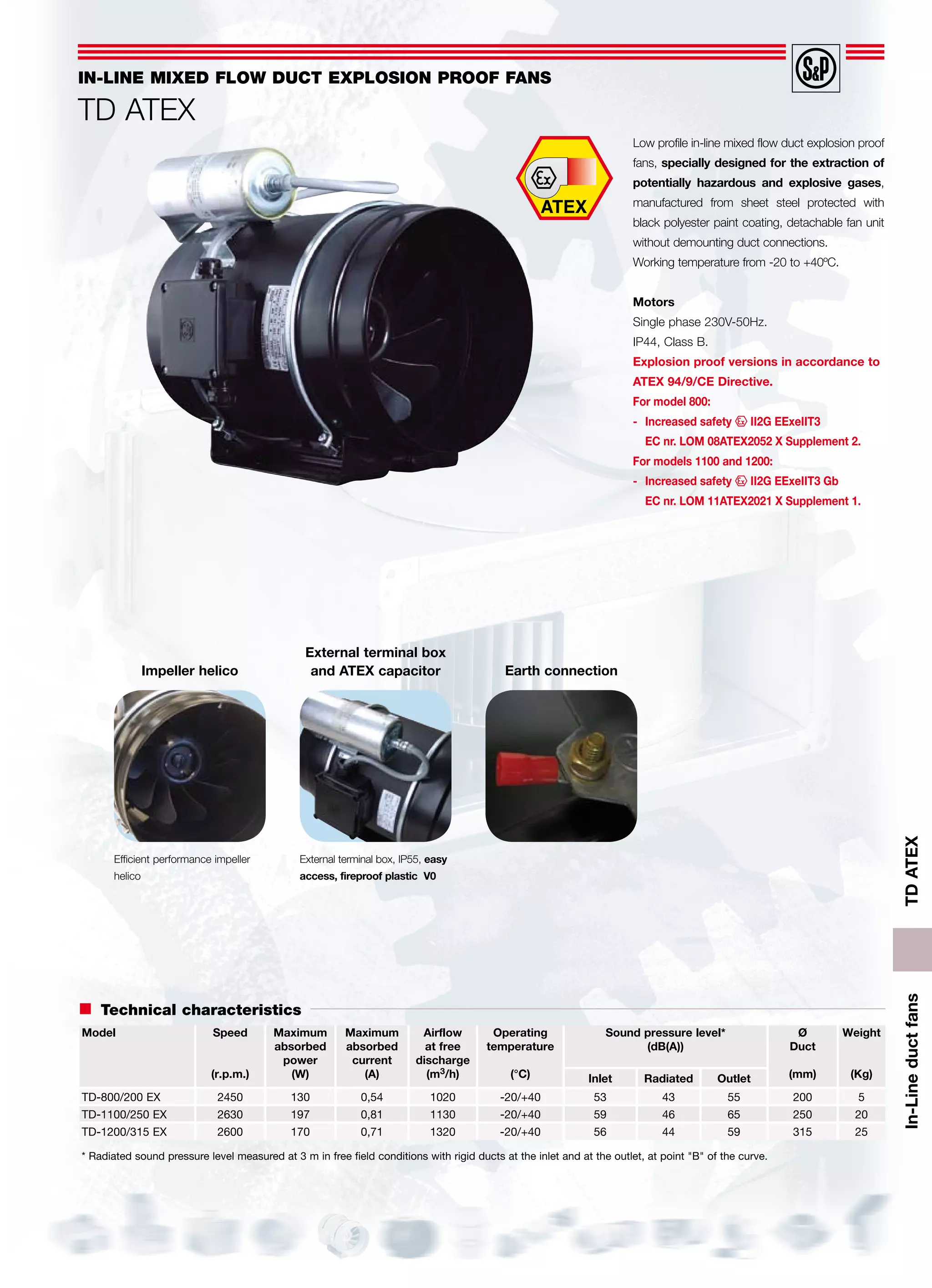
This document provides specifications for three models of low profile in-line mixed flow duct explosion proof fans:
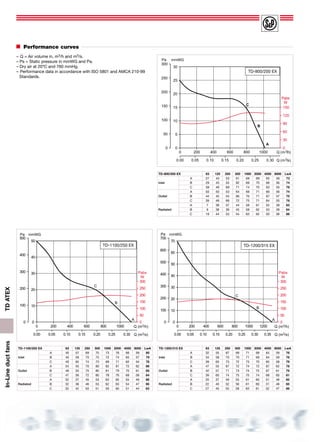
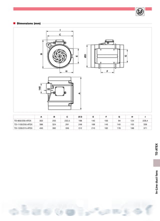
- Model TD-800/200 EX for ducts up to 200mm diameter, operating at 2450 rpm with maximum power of 130W
- Model TD-1100/250 EX for ducts up to 250mm diameter, operating at 2630 rpm with maximum power of 197W
- Model TD-1200/315 EX for ducts up to 315mm diameter, operating at 2600 rpm with maximum power of 170W
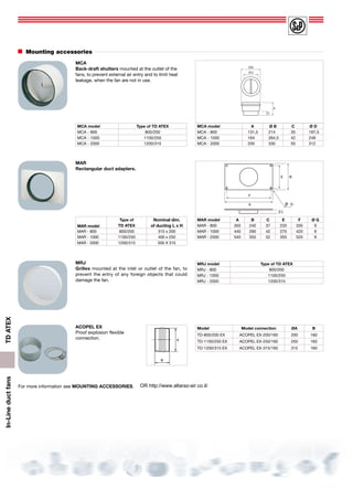
The fans are designed to extract potentially hazardous gases and comply with ATEX directives. Performance curves and dimensions are provided for each model along with mounting accessory options.