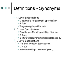
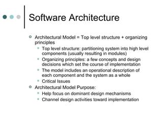
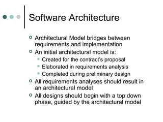
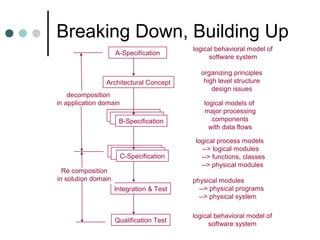
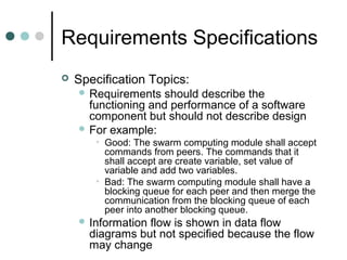
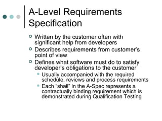
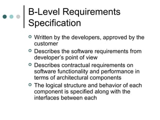
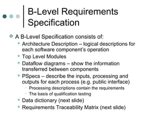
Software Architecture
and Specification
Derived from Dr. Fawcett’s slides
Phil Pratt-Szeliga
Fall 2010
Definitions - Synonyms






A Level Specifications
 Customer’s Requirement Specification
 A Spec
 Engineering Specifications
B Level Specifications
 Developer’s Requirement Specification
 B Spec
 Software Requirements Specification (SRS)
C Level Specifications
 “As Built” Product Specification
 C Spec
 Software Design Document (SDD)
Software Architecture




Architectural Model = Top level structure + organizing
principles
 Top level structure: partitioning system into high level
components (usually resulting in modules)
 Organizing principles: a few concepts and design
decisions which set the course of implementation
 The model includes an operational description of
each component and the system as a whole
 Critical Issues
Architectural Model Purpose:
 Help focus on dominant design mechanisms
 Channel design activities toward implementation
Software Architecture



Architectural Model bridges between
requirements and implementation
An initial architectural model is:
 Created

for the contract’s proposal
 Elaborated in requirements analysis
 Completed during preliminary design



All requirements analyses should result in
an architectural model
All designs should begin with a top down
phase, guided by the architectural model
Software Architecture
Life Cycle
- Developed during requirements
analysis
- Guides top level design and evolves
with design
- Should be fairly static during
implementation and testing
Software Components


Software Components: Parts of the
physical structure of a software
system
 Programs

are components of a
software system
 Modules are components of a
program
 Lower level modules, classes and
functions are components of a module
Software Components


The representation of a software
component consists of:
 Logical

Model: summary description of its
operation
 Behaviors: specific operations that a
component performs. Behaviors are
characterized by:
• Pre and Post conditions
• Invariants
 State:




values of internal data

Logical Models and Behaviors defined in BSpec
State and Control defined in C-Spec
Decomposition




All but the smallest and simplest software
systems need to be decomposed into
partitions
Partitioning is based on one or more
criteria:
 Logical

– identify important objects and the
processing for each
 Data Driven – decompose processing to
minimize data coupling. Promotes
robustness under change
 Requirements Design – Decompose along
A-Spec boundaries. Makes qualification
easier and boosts customer confidence
Decomposition


Partitioning is based on one or more
criteria:
 Usability

– Configure processing for simple,
model driven user interfaces
 Reuse – Partition into components so that
boundaries match existing software to be
reused
 Device Independence – Isolate all platform
processing
 Performance – Minimize data transport,
contention for resources, operator
intervention and balance workload in
distributed systems
Breaking Down


Software Requirements Analysis and
preliminary design are processes of
decomposition in the application domain
 Requirements

decomposed into processes

and data flows
 Process – logical model of some activity
necessary to satisfy part of requirements
 Data flows – represent information
necessary to sustain activities allocated to
the process
Breaking Down


Each process is allocated part of
application’s requirements model
 May

derive additional requirements to
complete or disambiguate processing model



Design Structure
 Developed

by associating major processes
with modules




Public interface of major modules represent
associated process and data flow
Each stage of decomposition needs to
allocate requirements to its component
parts to prove correctness of the design
Building Up


Detailed design and testing
 Process

domain







of recomposition in the solution

A logical module becomes a physical
module when its implementation is filled in
using functions and private data
Each function and class is tested for
conformance to its process model
Modules are populated in order of their
dependencies
This process continues until all system
requirements are met
Breaking Down, Building Up
A-Specification

logical behavioral model of
software system

Architectural Concept

organizing principles
high level structure
design issues

decomposition
in application domain
B-Specification

C-Specification
Re composition
in solution domain

logical models of
major processing
components
with data flows
logical process models
--> logical modules
--> functions, classes
--> physical modules

Integration & Test

physical modules
--> physical programs
--> physical system

Qualification Test

logical behavioral model of
software system
Requirements Specifications


Specification Purpose:
 Describe

the contractual obligations of the
developer to the customer
 Describe the allowable context –
programming language, platform, testing
scope, required reviews, schedule


Specification Goals:
 Completeness

- must describe all processing
 Unambiguous – must clearly state each
requirement
 Brief – no redundancy or extraneous
descriptors (no adjectives, no adverbs)
Requirements Specifications


Specification Topics:
 Requirements

should describe the
functioning and performance of a software
component but should not describe design
 For example:
• Good: The swarm computing module shall accept
commands from peers. The commands that it
shall accept are create variable, set value of
variable and add two variables.
• Bad: The swarm computing module shall have a
blocking queue for each peer and then merge the
communication from the blocking queue of each
peer into another blocking queue.
 Information

flow is shown in data flow
diagrams but not specified because the flow
may change
A-Level Requirements
Specification




Written by the customer often with
significant help from developers
Describes requirements from customer’s
point of view
Defines what software must do to satisfy
developer’s obligations to the customer
 Usually

accompanied with the required
schedule, reviews and process requirements
 Each “shall” in the A-Spec represents a
contractually binding requirement which is
demonstrated during Qualification Testing
A-Level Requirements
Specification


A-Level Specification Contains
 Logical

description of software’s operation
 A context diagram which shows developed
software as one process with external inputs
and outputs shown as rectangles
 A function and performance requirements
section
 Data dictionary which summarizes all
information flow into and out of the
developed software, only if it is quite
complex
A-Level Requirements
Specification Example


Duplicates A-Spec
 On

website – lecture 1
B-Level Requirements
Specification






Written by the developers, approved by the
customer
Describes the software requirements from
developer’s point of view
Describes contractual requirements on
software functionality and performance in
terms of architectural components
The logical structure and behavior of each
component is specified along with the
interfaces between each
B-Level Requirements
Specification


A B-Level Specification consists of:
 Architecture

Description – logical descriptions for
each software component’s operation
 Top Level Modules
 Dataflow diagrams – show the information
transferred between components
 PSpecs – describe the inputs, processing and
outputs for each process (e.g. public interface)
• Processing descriptions contain the requirements
• The basis of qualification testing
 Data

dictionary (next slide)
 Requirements Traceability Matrix (next slide)
B-Level Requirements
Specification
Data dictionary – lists each data flow
between components and to/from the
environment
 Requirement Traceability Matrix –
shows the allocation and derivation
relationships between A and B spec
requirements

B-Level Requirements
Specification


DFDs are constructed in a hierarchical
manner
 PSpec

matches a DFD process
 PSpec contains a HIPO (hierarchical
input, processing, output) section
which becomes the prologue for the
corresponding module which
implements it
Data Flow Diagram Example
Pspec 2
derived requirement:
shall find names of files in
default directory that match a
given filename pattern
getUniqueFileName
2

file
na
me

l
er
ad
he

s,
rn
tte
pa s
e nd
m a
na mm
file co

file
pat
ter

n

displayHeader
3

e
in

me
na
file

Pspec 1
shall accept a sequence
of filename patterns and
commands

TOP Executive
1

commands
filename,

parameters
file handle,

f
nu ile h
mb an
er dle
,
of
lin
es
file

processCL
5

Pspec 4
shall display first
few lines of file text
er
ro
r

xt
te

m
es
sa
ge

file

ha
nd
le

xt
te

displayFile
4

me
na
file

Pspec 5
shall recognize -n
command, set number of
lines to n, otherwise set
number of lines to 5
file

Pspec 3
shall display name of
each file processed
B-Specification Structure
1.

Architecture:
uses, tasks, views,
objects, events, interactions

2.

Referenced Documents

3.

Requirements:
Data Flow Diagrams
Process Specifications

4.

Data Dictionary:
Data Flow Names, Descriptions

5.

Requirements Tracability Matrix:
B-req, A-req or derived, description

6.

Notes
B-Level Specification
Example


Duplicates B-Spec
 On

website, lecture 1
B-Specification Hints






Specify what the software shall do, not how
Make testable requirements.
Be complete and unambiguous with shalls
Explicitly use the word “shall” for something
that must be done
Effective use of Context and DFD
Diagrams:
 Balance

– the outputs of the context diagram
are matched to the inputs of the top level
DFD. the inputs to a top level process match
up to a diagram of a lower level process
 Leveling – creating a hierarchy of data flow
diagrams



Numbers on DFD Processes must match
PSpecs
DD and RTM must be complete

Pressman ch-11-component-level-design

  • 1.
    Software Architecture and Specification Derivedfrom Dr. Fawcett’s slides Phil Pratt-Szeliga Fall 2010
  • 2.
    Definitions - Synonyms    ALevel Specifications  Customer’s Requirement Specification  A Spec  Engineering Specifications B Level Specifications  Developer’s Requirement Specification  B Spec  Software Requirements Specification (SRS) C Level Specifications  “As Built” Product Specification  C Spec  Software Design Document (SDD)
  • 3.
    Software Architecture   Architectural Model= Top level structure + organizing principles  Top level structure: partitioning system into high level components (usually resulting in modules)  Organizing principles: a few concepts and design decisions which set the course of implementation  The model includes an operational description of each component and the system as a whole  Critical Issues Architectural Model Purpose:  Help focus on dominant design mechanisms  Channel design activities toward implementation
  • 4.
    Software Architecture   Architectural Modelbridges between requirements and implementation An initial architectural model is:  Created for the contract’s proposal  Elaborated in requirements analysis  Completed during preliminary design   All requirements analyses should result in an architectural model All designs should begin with a top down phase, guided by the architectural model
  • 5.
    Software Architecture Life Cycle -Developed during requirements analysis - Guides top level design and evolves with design - Should be fairly static during implementation and testing
  • 6.
    Software Components  Software Components:Parts of the physical structure of a software system  Programs are components of a software system  Modules are components of a program  Lower level modules, classes and functions are components of a module
  • 7.
    Software Components  The representationof a software component consists of:  Logical Model: summary description of its operation  Behaviors: specific operations that a component performs. Behaviors are characterized by: • Pre and Post conditions • Invariants  State:   values of internal data Logical Models and Behaviors defined in BSpec State and Control defined in C-Spec
  • 8.
    Decomposition   All but thesmallest and simplest software systems need to be decomposed into partitions Partitioning is based on one or more criteria:  Logical – identify important objects and the processing for each  Data Driven – decompose processing to minimize data coupling. Promotes robustness under change  Requirements Design – Decompose along A-Spec boundaries. Makes qualification easier and boosts customer confidence
  • 9.
    Decomposition  Partitioning is basedon one or more criteria:  Usability – Configure processing for simple, model driven user interfaces  Reuse – Partition into components so that boundaries match existing software to be reused  Device Independence – Isolate all platform processing  Performance – Minimize data transport, contention for resources, operator intervention and balance workload in distributed systems
  • 10.
    Breaking Down  Software RequirementsAnalysis and preliminary design are processes of decomposition in the application domain  Requirements decomposed into processes and data flows  Process – logical model of some activity necessary to satisfy part of requirements  Data flows – represent information necessary to sustain activities allocated to the process
  • 11.
    Breaking Down  Each processis allocated part of application’s requirements model  May derive additional requirements to complete or disambiguate processing model  Design Structure  Developed by associating major processes with modules   Public interface of major modules represent associated process and data flow Each stage of decomposition needs to allocate requirements to its component parts to prove correctness of the design
  • 12.
    Building Up  Detailed designand testing  Process domain     of recomposition in the solution A logical module becomes a physical module when its implementation is filled in using functions and private data Each function and class is tested for conformance to its process model Modules are populated in order of their dependencies This process continues until all system requirements are met
  • 13.
    Breaking Down, BuildingUp A-Specification logical behavioral model of software system Architectural Concept organizing principles high level structure design issues decomposition in application domain B-Specification C-Specification Re composition in solution domain logical models of major processing components with data flows logical process models --> logical modules --> functions, classes --> physical modules Integration & Test physical modules --> physical programs --> physical system Qualification Test logical behavioral model of software system
  • 14.
    Requirements Specifications  Specification Purpose: Describe the contractual obligations of the developer to the customer  Describe the allowable context – programming language, platform, testing scope, required reviews, schedule  Specification Goals:  Completeness - must describe all processing  Unambiguous – must clearly state each requirement  Brief – no redundancy or extraneous descriptors (no adjectives, no adverbs)
  • 15.
    Requirements Specifications  Specification Topics: Requirements should describe the functioning and performance of a software component but should not describe design  For example: • Good: The swarm computing module shall accept commands from peers. The commands that it shall accept are create variable, set value of variable and add two variables. • Bad: The swarm computing module shall have a blocking queue for each peer and then merge the communication from the blocking queue of each peer into another blocking queue.  Information flow is shown in data flow diagrams but not specified because the flow may change
  • 16.
    A-Level Requirements Specification    Written bythe customer often with significant help from developers Describes requirements from customer’s point of view Defines what software must do to satisfy developer’s obligations to the customer  Usually accompanied with the required schedule, reviews and process requirements  Each “shall” in the A-Spec represents a contractually binding requirement which is demonstrated during Qualification Testing
  • 17.
    A-Level Requirements Specification  A-Level SpecificationContains  Logical description of software’s operation  A context diagram which shows developed software as one process with external inputs and outputs shown as rectangles  A function and performance requirements section  Data dictionary which summarizes all information flow into and out of the developed software, only if it is quite complex
  • 18.
  • 19.
    B-Level Requirements Specification     Written bythe developers, approved by the customer Describes the software requirements from developer’s point of view Describes contractual requirements on software functionality and performance in terms of architectural components The logical structure and behavior of each component is specified along with the interfaces between each
  • 20.
    B-Level Requirements Specification  A B-LevelSpecification consists of:  Architecture Description – logical descriptions for each software component’s operation  Top Level Modules  Dataflow diagrams – show the information transferred between components  PSpecs – describe the inputs, processing and outputs for each process (e.g. public interface) • Processing descriptions contain the requirements • The basis of qualification testing  Data dictionary (next slide)  Requirements Traceability Matrix (next slide)
  • 21.
    B-Level Requirements Specification Data dictionary– lists each data flow between components and to/from the environment  Requirement Traceability Matrix – shows the allocation and derivation relationships between A and B spec requirements 
  • 22.
    B-Level Requirements Specification  DFDs areconstructed in a hierarchical manner  PSpec matches a DFD process  PSpec contains a HIPO (hierarchical input, processing, output) section which becomes the prologue for the corresponding module which implements it
  • 23.
    Data Flow DiagramExample Pspec 2 derived requirement: shall find names of files in default directory that match a given filename pattern getUniqueFileName 2 file na me l er ad he s, rn tte pa s e nd m a na mm file co file pat ter n displayHeader 3 e in me na file Pspec 1 shall accept a sequence of filename patterns and commands TOP Executive 1 commands filename, parameters file handle, f nu ile h mb an er dle , of lin es file processCL 5 Pspec 4 shall display first few lines of file text er ro r xt te m es sa ge file ha nd le xt te displayFile 4 me na file Pspec 5 shall recognize -n command, set number of lines to n, otherwise set number of lines to 5 file Pspec 3 shall display name of each file processed
  • 24.
    B-Specification Structure 1. Architecture: uses, tasks,views, objects, events, interactions 2. Referenced Documents 3. Requirements: Data Flow Diagrams Process Specifications 4. Data Dictionary: Data Flow Names, Descriptions 5. Requirements Tracability Matrix: B-req, A-req or derived, description 6. Notes
  • 25.
  • 26.
    B-Specification Hints      Specify whatthe software shall do, not how Make testable requirements. Be complete and unambiguous with shalls Explicitly use the word “shall” for something that must be done Effective use of Context and DFD Diagrams:  Balance – the outputs of the context diagram are matched to the inputs of the top level DFD. the inputs to a top level process match up to a diagram of a lower level process  Leveling – creating a hierarchy of data flow diagrams   Numbers on DFD Processes must match PSpecs DD and RTM must be complete