Software Requirements (3rd Edition) summary
•Download as DOCX, PDF•
4 likes•2,990 views

The document discusses software requirements from the perspective of customers and stakeholders. It defines key terms like business requirements, functional requirements, and non-functional requirements. It emphasizes the importance of frequent engagement with customers to understand their needs and manage expectations. This ensures the developed software closely matches what customers require rather than making assumptions. The document also discusses identifying all relevant stakeholders to obtain a full picture of requirements, such as direct users, indirect users, and others affected by the system.

Recommended
More Related Content
What's hot
What's hot (20)
Similar to Software Requirements (3rd Edition) summary
Similar to Software Requirements (3rd Edition) summary (20)
More from Ahmed Kamel Taha
More from Ahmed Kamel Taha (19)
Recently uploaded
Recently uploaded (20)
Software Requirements (3rd Edition) summary
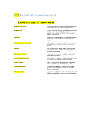
- 1. Ch.1 The essential software requirement Levels and types of requirements Term Definition Business requirement A high-level businessobjective of the organization that buildsa product or of a customer who procuresit. Business rule A policy, guideline,standard, or regulationthat definesor constrainssome aspect of the business. Not a software requirementin itself, but theorigin of several typesof software requirements. Constraint A restriction that isimposed on the choicesavailableto the developer for the design and constructionof a product. External interface requirement A description of a connectionbetweena software system and a user, another software system, or a hardware device. Feature One or more logically related system capabilitiesthat provide value to a user and are described by a set of functional requirements. Functional requirement A description of a behavior that a system will exhibit under specific conditions. Nonfunctional requirement A description of a property or characteristic that a system must exhibit or a constraint that it must respect. Quality attribute A kind of nonfunctional requirementthat describesa service or performance characteristic of a product. System requirement A top-level requirementfor a product that contains multiplesubsystems, which could be all software or software and hardware. User requirement A goal or task that specific classes of users must be able to perform with a system, or a desired product attribute.
- 2. FIGURE 1-1 Relationships among several typesofrequirements information. Solidarrowsmean “are storedin”; dotted arrowsmean “are the origin of” or“influence.” FIGURE 1-2 Relationships among features,userrequirements,andfunctionalrequirements.
- 3. Working withthe three levels FIGURE 1-3 An example of how different stakeholders participatein requirementsdevelopment. Product vs. project requirements Physical resources the development team needs, such as workstations, special hardware devices, testing labs, testing tools and equipment, team rooms, and videoconferencing equipment. Staff training needs. User documentation, including training materials, tutorials, reference manuals, and release notes. Support documentation, such as help desk resources and field maintenanceand service information for hardware devices. Infrastructure changes needed in the operating environment. Requirements and procedures for releasing the product, installing it in the operating environment, configuring it, and testing the installation.
- 4. Requirements and procedures for transitioning from an old system to a new one, such as data migration and conversion requirements, security setup, production cutover, and training to close skills gaps; these are sometimes called transition requirements. Product certification and compliancerequirements. Revised policies, processes, organizational structures, and similar documents. Sourcing, acquisition, and licensing of third-party software and hardware components. Beta testing, manufacturing, packaging, marketing, and distribution requirements. Customer service-level agreements. Requirements for obtaining legal protection (patents, trademarks, or copyrights) for intellectual property related to the software. Requirements development and management FIGURE 1-4 Subdisciplines of software requirementsengineering. Requirementsdevelopment Elicitation Elicitation encompasses all of the activities involved with discovering requirements, such as interviews, workshops, document analysis, prototyping, and others. The key actions are: Identifying the product’s expected user classes and other stakeholders. Understanding user tasks and goals and the business objectives with which those tasks align. Learning about the environment in which the new product will be used. Working with individuals who represent each user class to understand their functionality needs and their quality expectations.
- 5. Analysis Analyzing requirements involves reaching a richer and more precise understanding of each requirement and representing sets of requirements in multiple ways. Following are the principal activities: Analyzing the information received from users to distinguish their task goals from functional requirements, quality expectations, business rules, suggested solutions, and other information Decomposing high-level requirements into an appropriate level of detail Deriving functional requirements from other requirements information Understanding the relative importance of quality attributes Allocating requirements to software components defined in the system architecture Negotiating implementation priorities Identifying gaps in requirements or unnecessary requirements as they relate to the defined scope Specification Requirements specification involves representing and storing the collected requirements knowledge in a persistent and well-organized fashion. The principal activity is: Translating the collected user needs into written requirements and diagrams suitable for comprehension, review, and use by their intended audiences. Validation Requirements validation confirms that you have the correct set of requirements information that will enable developers to build a solution that satisfies the business objectives. The central activities are: Reviewing the documented requirements to correct any problems before the development group accepts them. Developing acceptance tests and criteria to confirm that a product based on the requirements would meet customer needs and achievethe business objectives. Requirements management Defining the requirements baseline, a snapshot in time that represents an agreed-upon, reviewed, and approved set of functional and nonfunctional requirements, often for a specific product release or development iteration Evaluating the impact of proposed requirements changes and incorporating approved changes into the project in a controlled way Keeping project plans current with the requirements as they evolve Negotiating new commitments based on the estimated impact of requirements changes Defining the relationships and dependencies that exist between requirements
- 6. Tracing individual requirements to their corresponding designs, source code, and tests Tracking requirements status and change activity throughout the project FIGURE 1-5 The boundary between requirements development andrequirements management. When bad requirements happen to good people Insufficient user involvement Customers often don’t understand why it is so essential to work hard on eliciting requirements and assuring their quality. Developers might not emphasize user involvement, perhaps because they think they already understand what the users need. Inaccurate planning “Here’s my idea for a new product; when will you be done?” No one should answer this question until more is known about the problem being discussed. Vague, poorly understood requirements lead to overly optimistic estimates, which come back to haunt you when the inevitable overruns occur. Creeping user requirements As requirements evolve during development, projects often exceed their planned schedules and budgets (which are nearly always too optimistic anyway). To manage scopecreep, begin with a clear statement of the project’s business objectives, strategic vision, scope, limitations, and success criteria. Evaluate all proposed new features or requirements changes against this reference.
- 7. Ambiguous requirements informal peer reviews in which reviewers simply read the requirements on their own often don’t reveal ambiguities. If different reviewers interpret a requirement in different ways but it makes sense to each of them, they won’t find the ambiguity. Collaborative elicitation and validation encourages stakeholders to discuss and clarify requirements as a group in a workshop setting. Writing tests against the requirements and building prototypes are other ways to discover ambiguities. Gold plating Gold plating takes place when a developer adds functionality that wasn’t in the requirements Specification. Overlooked stakeholders You might have stakeholders who don’t even know the project exists, such as government agencies that mandate standards that affect your system, yet you need to know about them and their influence on the project. Benefits from a high-quality requirements process Fewer defects in requirements and in the delivered product. Reduced development rework. Faster development and delivery. Fewer unnecessary and unused features. Lower enhancement costs. Fewer miscommunications. Reduced scopecreep. Reduced project chaos. Higher customer and team member satisfaction. Products that do what they’re supposed to do.
- 8. Ch.2 Requirements from the customer’s perspective The expectation gap The best way to minimize the expectation gap is to arrange frequent contact points with suitable customer representatives. These contact points can take the form of interviews, conversations, requirements reviews, user interface design walkthroughs, prototype evaluations, and—with agile development—user feedback on small increments of executable software. Each contact point affords an opportunity to close the expectation gap: what the developer builds is more closely aligned with what the customer needs. FIGURE 2-1 Frequent customer engagementreducesthe expectation gap. Who is the customer? A stakeholderis a person, group, or organization that is actively involved in a project, is affected by its process or outcome, or can influenceits process or outcome. Stakeholders can be internal or external to the project team and to the developing organization.
- 9. FIGURE 2-2 Potentialstakeholders within theproject team, within thedevelopingorganization,and outsidethe organization. Direct users will operate the product hands-on. Indirect users might receive outputs from the system without touching it themselves, such as a warehouse manager who receives an automatic report of daily warehouse activities by email. The customer-development partnership TABLE 2-1 Requirements Bill of Rights for Software Customers You have the right to 1. Expect BAs to speak your language. 2. Expect BAs to learn about your busine ss and your objectives. 3. Expect BAs to record requirements in an appropriate form. 4. Receive explanations of requirements practices and deliverables. 5. Change your requirements. 6. Expect an environment of mutual respect.
- 10. 7. Hear ideas and alternatives for your requirements and for their solution. 8. Describe characteristics that will make the product easy to use. 9. Hear about ways to adjust requirements to accelerate development through reuse. 10. Receive a system that meets your functional needs and quality expectations. TABLE 2-2 Requirements Bill of Responsibilities for Software Customers You have the responsibility to 1. Educate BAs and developers about your business. 2. Dedicate the time that it takes to provide and clarify requirements. 3. Be specific and precise when providing input about requirements. 4. Make timely decisions about requirements when asked. 5. Respect a developer’s asses sment of the cost and feasibility of requirements. 6. Set realistic requirement priorities in collaboration with developers. 7. Review requirements and evaluate prototypes. 8. Establish acceptance criteria. 9. Promptly communicate changes to the requirements. 10. Respect the requirements development process. Requirements Bill of Rights for Software Customers Right #4: To receive explanations of requirements practices and deliverables BA might create some diagrams to complementtextual requirements The BA should explain the purpose of each diagram, what the symbols mean, and how to examine the diagram for errors. If the BA doesn’t offer such explanations, feel free to ask for them. Right #7: To hear ideas and alternatives for your requirements and for their solution A BA can often suggest improvements in your business processes. Right #8: To describe characteristics that will make the product easy to use
- 11. Users sometimes request that the product be user-friendly or robust, but such terms are too subjective to help the developers. Instead, the analyst should inquire about the specific characteristics that mean “user- friendly” or “robust” to you. Right #9: To hear about ways toadjust requirements to accelerate development through reuse Some requirements flexibility is essential if you want to incorporate commercial off-the-shelf (COTS) packages into the product, because they will rarely have precisely the characteristics you want. Requirements Bill of Responsibilities for Software Customers Responsibility #3: To bespecific and precise when providing input about requirements It’s fine to temporarily includeto be determined (TBD) markers in the requirements to indicate that additional exploration or information is needed. Sometimes, though, TBD is used because a specific requirement is difficult to resolve and no one wants to tackle it. Responsibility #4: To make timely decisions about requirements when asked These includeresolving conflicting requests received from multiple customers, choosing between incompatiblequality attributes, and evaluating the accuracy of information Responsibility #6: To set realistic requirement priorities in collaboration with developers Developers can provide information about the cost and risk of each requirement or user story to help determine final priorities. Responsibility #8: To establish acceptance criteria Such criteria includeacceptancetests, which assess whether the product lets users perform certain of their important business operations correctly. Other acceptancecriteria might address the estimated remaining defect levels, the performance of certain actions in the operating environment, or the ability to satisfy external certification requirements. Responsibility #10: To respect the requirements development process Although you might become frustrated, the time spent understanding requirements is an excellent investment. Identifying decision makers The decision-making group needs to identify its decision leaderand to select a decision rule, which describes how they will arrive at their decisions. Thedecision leader makes the choice, either with or without discussion with others. Thegroup votes and the majority rules. Thegroup votes, but the result must be unanimous to approve the decision.
- 12. Thegroup discusses and negotiates to reach a consensus. Everyone can live with the decision and commits to supporting it. Thedecision leader delegates authority for making the decision to one individual. Thegroup reaches a decision, but someindividual has veto authority over that decision. Reaching agreement on requirements Customers agree that the requirements address their needs. Developers agree that they understand the requirements and that they are feasible. Testers agree that the requirements are verifiable. Management agrees that the requirements will achieve their business objectives. The requirements baseline A requirements baseline is a set of requirements that has been reviewed and agreed upon and serves as the basis for further development. What if you don’t reach agreement? Barriers include logistics, busy schedules, and people who are reluctant to commit and be held accountable later. In such a situation, you’re better off moving forward—cautiously—with the assumption that you don’t have approval from the recalcitrant stakeholders. Document the fact that certain stakeholders didn’t sign off on the requirements in your risk list. Follow up with these people as part of risk management. Agreeing on requirements on agile projects Agile projects do not include a formal sign-off action. In agile projects the full set of functionality is identified over time, although the vision and other business requirements do need to be established at the outset.
- 13. Ch.3 Goodpractices for requirement engineering TABLE 3-1 Requirements engineering good practices Elicitation Analysis Specification Validation Define vision and scope Identify user classes Select product champions Conduct focus groups Identify user requirements Identify system events and responses Hold elicitation interviews Hold facilitated elicitation workshops Observe users performing their jobs Distribute questionnaires Perform document analysis Examine problem repor ts Reuse existing requirements Model the application environment Create prototypes Analyze feasibility Prioritize requirements Create a data dictionary Model the requirements Analyze interfaces Allocate requirements to subsystems Adopt requirement document templates Identify requirement origins Uniquely label each requirem ent Record business rules Specify nonfunctional requirements Review the requirements Test the requirements Define acceptance criteria Simulate the requirements Requirements management Knowledge Project management Establish a change control process Perform change impact analysis Establish baselines and control versions of requirements sets Maintain change history Track requirements status Track requirements issues Maintain a requirements traceability matrix Use a requirements management tool Train business analysts Educate stakehold er s about requirements Educate developers about application domain Define a requirements engineering process Create a glossary Select an appropriate life cycle Plan requirements approach Estimate requirements effort Base plans on requirements Identify requirements decision makers Renegotiate commitments Manage requirements risks Track requirements effort Review past lessons learned A requirements development process framework FIGURE 3-1 Requirements development is an iterative process.
- 14. While writing requirements, you might need to go back and do some additional analysis to closegaps in your knowledge. Validation could lead you to rewrite some unclear requirements,revisitsome ofyour analysis activities,or even have to go back and perform additional elicitation. FIGURE 3-2 A representative requirementsdevelopment process. The first seven steps are typically performed once early in the project. The remaining steps are performed for each release or developmentiteration. FIGURE 3-3 The distribution ofrequirements developmenteffort over timevaries for projectsthat follow different developmentlife cycles. Agile and other incremental development projects aim to release functionality every few weeks. They will have frequent but small requirements development efforts.
- 15. Good practices: Requirements elicitation Define product vision and project scope The vision and scope document contains the product’s business requirements. The vision statement gives all stakeholders a common understanding of the product’s outcome. The vision should remain relatively stable throughout the project, but each planned release or iteration needs its own scope statement. Conduct focus groups with typical users Focus groups are particularly valuable for commercial product development, for which you might have a large and diverse customer base. Identify system events and responses List the external events that the system can experience and its expected response to each event. Hold facilitated elicitation workshops Facilitated requirements-elicitation workshops that permit collaboration between analysts and customers are a powerful way to explore user needs and to draft requirements documents. Good practices: Requirements analysis Model the application environment The context diagram is a simple analysis model that shows how the new system fits into its environment. It defines the boundaries and interfaces between the system being developed and external entities, such as users, hardware devices, and other systems. Model the requirements An analysis model is a diagram that depicts requirements visually, in contrast to the textual representation of a list of functional requirements. Analyze interfaces between your system and the outside world Embedded systems involve interconnections between software and hardware components. Network- connected applications have communication interfaces. Good practices: Requirements specification Identify requirement origins This might be a use case or someother customer input, a high-level system requirement, or a business rule. Recording the stakeholders who are affected by each requirement tells you whom to contact when a change is requested. Requirement origins can be identified through traceability links or by defining a requirement attribute for this purpose.
- 16. Record business rules Business rules include corporate policies, government regulations, standards, and computational algorithms. Document your business rules separately from a project’s requirements because they typically have an existence beyond the scopeof a specific project. Good practices: Requirements validation Review the requirements Peer review of requirements, particularly the type of rigorous review called inspection. Assemble a small team of reviewers who represent different perspectives (such as analyst, customer, developer, and tester), and carefully examine the written requirements, analysis models, and related information for defects. It’s important to train the team members in how to perform effective requirements reviews and to adopt a review process for your organization. Test the requirements Derive tests from the user requirements to document the expected behavior of the product under specified conditions. Define acceptance criteria Acceptancecriteria includea combination of the software passing a defined set of acceptance tests based on user requirements, demonstrating satisfaction of specific nonfunctional requirements, tracking open defects and issues, having infrastructure and training in place for a successful rollout, and more. Simulate the requirements Simulation takes prototyping to the next level, by letting BAs work with users to rapidly build executable mock-ups of a system. Users can interact with the simulated system to validate requirements and make design choices, making the requirements cometo life before they are cast into the concrete of code. Simulation is not a substitute for thoughtful requirements elicitation and analysis, but it does provide a powerful supplement. Good practices: Requirements management Effective change management demands a process for proposing changes, evaluating their potential cost and impact on the project, store requirements in a requirements management tool, which provides many capabilities to perform these practices. Establish a requirements change control process Rather than stifling changeor hoping changes don’t happen, accept the fact that they will and establish a mechanism to prevent rampant changes from causing chaos. Your change process should define how requirements changes are proposed, analyzed, and resolved. Manage all proposed changes through this process. Defect-tracking tools can support the change control process. Charter a small group of project stakeholders as a change control board (CCB) to evaluate proposed requirements changes, decide which ones to accept, and set implementation priorities or target releases.
- 17. Perform impact analysis on requirements changes Impact analysis is an important element of the change process that helps the CCB makeinformed business decisions. Evaluate each proposed requirement change to assess the effect it will have on the project. Use the requirements traceability matrix to identify the other requirements, design elements, sourcecode, and tests that you might need to modify. Establish baselines and control versions of requirements sets A baseline defines a set of agreed-upon requirements, typically for a specific release or iteration. Track requirements issues When busy people are working on a complexproject, it’s easy to lose sight of the many issues that arise, including questions about requirements that need resolution, gaps to eradicate, and issues arising from requirements reviews. Maintain a requirements traceability matrix It’s often valuable—and sometimes required—to assemble a set of links that connect each functional requirement to the design and codeelements that implement it and thetests that verify it. Such a requirements traceability matrixis helpful for confirming that all requirements are implemented and verified. Good practices: Knowledge Educate stakeholders about requirements Users who will participate in software development should receive one or two days of education about requirements so they understand terminology, key concepts and practices, and why this is such an important contributor to project success Define a requirements engineering process Document the steps your organization follows to elicit, analyze, specify, validate, and manage requirements. Create a glossary A glossary that defines specialized terms from the application domain will minimize misunderstandings. Include synonyms, acronyms or abbreviations, terms that can have multiple meanings, and terms that have both domain-specific and everyday meanings. Good practices: Project management Plan requirements approach Each project team should plan how it will handle its requirements development and management activities. Identify requirements decision makers Conflicting user inputs must be resolved, commercial package components must be selected, change requests must be evaluated, and on and on. Analyze, document, and manage requirements-related risks Brainstorm approaches to mitigate or prevent these risks, implement the mitigation actions, and track their progress and effectiveness.
- 18. Getting started with new practices TABLE 3-2 Implementing requirements engineering good practices Value Difficulty High Define a requirements engineering process Base plans on requirements Renegotiate commitments Medium Low High Train business analysts Plan requirements approach Select product champions Identify user requirements Hold elicitation interviews Specify nonfunctional requirements Prioritize requirements Define vision and scope Establish a change control process Review the requirements Allocate requirements to subsystems Use a requirements management tool Record business rules Educate developers about application domain Adopt requirement document templates Identify user classes Model the application environment Identify requirement origins Establish baselines and control versions of requirements sets Identify requirements decision makers Medium Maintain a requirements traceability matrix Hold facilitated elicitation workshops Estimate requirements effort Reuse existing requirements Educate stakeholder s about requirem ents Conduct focus groups Create prototypes Analyze feasibility Define acceptance criteria Model the requirements Analyze interfaces Perform change impact analysis Select an appropriate life cycle Identify system events and responses Manage requirements risks Review past lessons learned Track requirements effort Create a data dictionary Observe users performing their jobs Test the requirements Track requirements status Perform document analysis Track requirements issues Uniquely label each requirem ent Create a glossary Low Distribute questionnaires Maintain change history Simulate the requirements Examine problem reports
- 19. Ch.4 Thebusinessanalyst The business analyst role FIGURE 4-1 The business analyst bridges communication between customerand development stakeholders. Business analyst is a project role, not necessarily a job title. Synonyms for business analyst include requirements analyst, systems analyst, requirements engineer, requirements manager, application analyst, business systems analyst, IT business analyst, and simply analyst. The business analyst’s tasks Define business requirements Plan the requirements approach Identify project stakeholders and user classes Elicit requirements Analyze Document requirements Communicate requirements Lead requirements validation Facilitate requirements prioritization Manage requirements Essential analyst skills Listening skills Interviewing and questioning skills Thinking on your feet You need to draft good questions, listen clearly to the responses, and quickly comeup with the next smart thing to say or ask.
- 20. Analytical skills An effective business analyst can think at both high and low levels of abstraction and knows when to move from one to another. Systems thinking skills see the big picture. The BA must check requirements against what he knows about the whole enterprise, the business environment, and the application to look for inconsistencies and impacts. Learning skills Analysts must learn new material quickly Facilitation skills Leadership skills Observational skills Communication skills Organizational skills Modeling skills Models ranging from the venerable flowchart through structured analysis models (data flow diagram, entity-relationship diagram, and similar diagrams) to Unified Modeling Language Interpersonal skills Analysts must be able to get people with competing interests to work together as a team Creativity They conceiveinnovative product capabilities, imaginenew markets and business opportunities, and think of ways to surprise and delight their customers. The making of a business analyst Great business analysts are grown from diverse backgrounds of education and work experience, The former user Corporate IT departments often have business analysts who migrated into that role after working on the business side as a user of information systems. Theseindividuals understand the business and the work environment, so they can easily gain the trust of their former colleagues. The former developer or tester The former (or concurrent) project manager The subject matter expert There are risks here, though, too. Thebusine ss analyst who is a domain expert might specify the system’s requirements to suit his own preferences, rather than addressing the legitimate needs of the various user classes. The rookie
- 21. FIGURE 4-2 Knowledge, skills,and experiencefeedintocreatingan effectivebusiness analyst. The analyst role on agile projects Some agile approaches have a key team member called the product owner. The person in that role might perform someof the traditional busine ss analysis activities, as well as providing the product vision, communicating constraints, prioritizing the product backlog of remaining work, and making the ultimate decisions about the product.
- 22. Ch.5 Establishing the business requirements TODO Defining business requirements “Business requirements” refers to a set of information that, in the aggregate, describes a need that leads to one or more projects to deliver a solution and the desired ultimate business outcomes. Business opportunities, business objectives, success metrics, and a vision statement make up the business requirements. The business requirements provide a reference for making decisions about proposed requirement changes and enhancements. Identifying desired business benefits Business requirements might comefrom funding sponsors, corporate executives, marketing managers, or product visionaries. Sometimes, sponsors don’t want to set objectives in a measurable fashion and then be held accountable for achieving them. The business benefit has to represent a true value for the project’s sponsors and to the product’s customers. Customers don’t care if they are using an application that involves 1, 5, or even 10 systems. They care about issues like increasing revenue and decreasing costs. Regulatory and legal complianceprojects also have clear business objectives. Often the objectives are phrased as risk avoidance, possibly to avoid getting sued or being put out of business. Product vision and project scope product vision succinctly describes the ultimate product that will achieve the business objectives. This product could serve as the completesolution for the business requirements or as just a portion of the solution. The project scope identifies what portion of the ultimate product vision the current project or development iteration will address. FIGURE 5-1 The product vision encompasses the scope foreach plannedrelease,which is less well definedthe farther out you look.
- 23. Conflicting business requirements FIGURE 5-2 Stakeholders for a kiosk don’t always havecongruent business interests. Vision and scope document FIGURE 5-3 Suggested template for a vision andscopedocument. 1. Business requirements The business requirements describe the primary benefits that the new system will provide to its sponsors, buyers, and users. 1.1 Background
- 24. Summarize the rationale and context for the new product or for changes to be made to an existing one. Describe the history or situation that led to the decision to build this product. 1.2 Business opportunity For a corporate information system, describe the business problem that is being solved or the process being improved, as well as the environment in which the system will be used. For a commercial product, describe the business opportunity that exists and the market in which the product will be competing. 1.3 Business objectives Summarize the important business benefits the product will provide in a quantitative and measurable way. TABLE 5-1 Examples of financial and nonfinancial business objectives Financial Nonfinancial Capture a market share of X% within Y months. Increase market share in country W from X% to Y% within Z months. Reach a sales volume of X units or revenue of $Y within Z months. Achieve X% return on investment within Y months. Achieve positive cash flow on this product within Y months. Save $X per year currently spent on a high-maintenance legacy system. Reduce monthly support costs from $X to $Y within Z months. Increase gross margin on existing business from X% to Y% within 1 year. Achieve a customer satisfaction measure of at least X within Y months of release. Increase transactio n-pr oc essing productivity by X% and reduce data error rate to no more than Y%. Develop an extensible platform for a family of related products. Develop specific core technology competencies. Be rated as the top product for reliability in published product reviews by a specified date. Comply with specific federal and state regulations. Receive no more than X service calls per unit and Y warranty calls per unit within Z months after shipping. Reduce turnaround time to X hours on Y% of support calls. 1.4 Success metrics Specify the indicators that stakeholders will use to define and measure success on this project one success metric might be the same as Business Another success metric might relate to Business Objective 2 with a timeline that can be measured much earlier than a year after release.
- 25. FIGURE 5-5 Example business objectives modelfor the ChemicalTrackingSystem. 1.5 Vision statement Write a concisevision statement that summarizes the long-term purpose and intent of the product. It can be somewhat idealistic but should be grounded in the realities of existing or anticipated markets, enterprise architectures, corporate strategic directions, and resource limitations. For [target customer] Who [statement of the need or opportunity] The [product name] Is [product category] That [major capabilities, key benefit, compelling reason to buy or use] Unlike [primary competitivealternative, current system, current business process]
- 26. Our product [statement of primary differentiation and advantages of new product] 1.6 Business risks Summarize the major business risks associated with developing—or not developing—this product. Risk categories includemarketplace competition, timing issues, user acceptance, implementation issues, and possible negative impacts on the business. Business risks are not the same as project risks, which often include resource availability concerns and technology factors. 1.7 Business assumptions and dependencies An assumption is a statement that is believed to be true in the absence of proof or definitive knowledge. Record any major dependencies the project has on external factors. Examples are pending industry standards or government regulations, deliverables from other projects, third-party suppliers, or development partners. Some business assumptions and dependencies might turn into risks that the project manager must monitor regularly. 2.Scope and limitations You need to state both what the solution being developed is and what it is not. The scopedescribes the concept and range of the proposed solution. 2.1 Major features List the product’s major features or user capabilities, emphasizing those that distinguish it from previous or competing products. 2.2 Scope of initial release Summarize the capabilities that are planned for inclusion in the initial product release. Scope is often defined in terms of features, but you can also define scopein terms of user stories, use cases, use case flows, or external events. Be careful not to neglect nonfunctional requirements in the initial release, though. The ones that directly affect architecture are particularly critical to establish from the outset. 2.3 Scope of subsequent releases Subse quent release s let you implement additional use cases and features, as well as enriching the capabilities of the initial ones. 2.4 Limitations and exclusions List any product capabilities or characteris tics that a stakeholder might expect but that are not planned for inclusion in the product or in a specific release. List items that were cut from scope, so the scopedecision is not forgotten. 3.Business context This section presents profiles of major stakeholder categories, management’s priorities for the project, and a summary of somefactors to consider when planning deployment of the solution. 3.1 Stakeholder profiles
- 27. Stakeholders are the people, groups, or organizations that are actively involved in a project, are affected by its outcome, or are able to influence its outcome.The stakeholder profiles describe different categories of customers and other key stakeholders for the project. Each stakeholder profile should include the following information: Themajor value or benefit that the stakeholder will receive from the product. Stakeholder value could be defined in terms of: • Improved productivity. • Reduced rework and waste. • Cost savings. • Streamlined business processes. • Automation of previously manual tasks. • Ability to perform entirely new tasks. • Compliancewith pertinent standards or regulations. • Improved usability compared to current products. Their likely attitudes toward the product. Major features and characteristics of interest. Any known constraints that must be accommodated. 3.2 Project priorities To enable effective decision making, the stakeholde rs must agree on the project’s priorities. One way to approach this is to consider the five dimensions of features, quality, schedule, cost, and staff. Constraint A limiting factor within which the project manager must operate Driver A significant success objective with limited flexibility for adjustment Degree of freedom A factor that the project manager has some latitude to adjust and balance against the other dimensions The project manager’s challenge is to adjust the degrees of freedom to achieve the project’s success drivers within the limits imposed by the constraints. 3.3 Deployment considerations Summarize the information and activities that are needed to ensure an effective deployment of the solution into its operating environment. Describe the access that users will require to use the system, such as whether the users are distributed over multipletime zones or located closeto each other. If infrastructure changes are needed to support the software’s need for capacity, network access, data storage, or data migration, describe those changes.
- 28. Scope representation techniques Context diagram The scopedescription establishes the boundary and connections between the system you’re developing and everything else in the universe. The context diagramvisually illustrates this boundary. It identifies external entities (also called terminators) outside the system that interface to it in some way, as well as data, control, and material flows between the terminators and the system. FIGURE 5-6 Partial context diagramfortheChemical Tracking System. Ecosystem map An ecosystem map shows all of the systems related to the system of interest that interact with one another and the nature of those interactions. An ecosystem map represents scope by showing all the systems that interconnect and that therefore might need to be modified to accommodateyour new system.
- 29. FIGURE 5-7 Partial ecosystem map for the Chemical TrackingSystem. Feature tree A feature tree is a visual depiction of the product’s features organized in logical groups, hierarchically subdividing each feature into further levels of detail. Thefeature tree provides a conciseview of all of the features planned for a project, making it an ideal model to show to executives who want a quick glance at the project scope. A feature tree can show up to three levels of features, commonly called level 1 (L1), level 2 (L2), and level 3 (L3). L2 features are subfeatures of L1 features, and L3 features are subfeatures of L2 features. FIGURE 5-8 Partial feature treefor the ChemicalTrackingSystem.
- 30. Event list An event list identifies external events that could trigger behavior in thesystem. Theevent list depicts the scopeboundary for thesystem by naming possible business events triggered by users, time-triggered (temporal) events, or signal events received from external components, such as hardwaredevices. The event list only names theevents; thefunctional requirements that describehow thesystem responds to theevents would bedetailed in theSRS by using event-response tables. FIGURE 5-9 Partial event listfor the ChemicalTrackingSystem. Vision and scope on agile projects Managing scope on an agile project, in which development is performed in a series of fixed timebox iterations, takes a different approach. Instead of trying to fight scopecreep, the team prioritizes new requirements against existing items in the backlog and allocates them to future iterations.
- 31. Ch.7 Requirements elicitation Elicitation is a collaborative and analytical process that includes activities to collect, discover, extract, and define requirements. Elicitation is used to discover business, user, functional, and nonfunctional requirements, along with other types of information. Requirements elicitation is perhaps the most challenging, critical, error-prone, and communication-intensiveaspect of software development. The output of requirements development is a common understanding of the needs held by the diverse project stakeholders. Emphasizing user tasks rather than user interfaces, and focusing on true needs more than on expressed desires, help keep the team from being sidetracked by prematurely specifying design details. FIGURE 7-1 The cyclic nature ofrequirements elicitation, analysis, and specification. FIGURE 7-2 Activities for a singlerequirements elicitation session. Requirements elicitation techniques Interviews Agile projects makeextensive use of interviews as a mechanism to get direct user involvement Interviews are appropriate for eliciting business requirements from executives who do not have a lot of time to meet. Establish rapport To begin an interview, introduce yourself if the attendees don’t already know you, review the agenda, remind attendees of the session objectives, and address any preliminary questions or concerns attendees have.
- 32. Stay in scope As with any elicitation session, keep the discussion focused on its objective. Prepare questions and straw man models ahead of time Prepare for interviews by drafting any materials you can beforehand, such as a list of questions to guide the conversation. Suggest ideas Rather than simply transcribing what customers say, a creative BA proposes ideas and alternatives during elicitation. Listen actively Practicethe techniques of active listening (leaning forward, showing patience, giving verbal feedback, and inquiring when something is unclear) and paraphrasing (restating the main idea of a speaker’s message to show your understanding of that message). Workshops Workshops encourage stakeholder collaboration in defining requirements. requirements workshop as “a structured meeting in which a carefully selected group of stakeholders and content experts work together to define, create, refine, and reach closure on deliverables (such as models and documents) that represent user requirements.” The facilitator plays a critical role in planning the workshop, selecting participants, and guiding them to a successful outcome. A scribe assists the facilitator by capturing the points that comeup during the discussion Establish and enforce ground rules Theworkshop participants should agree on some basic operating principles. Fill all of the team roles A facilitator must makesure that the following tasks are covered by people in the workshop: note taking, time keeping, scope management, ground rule management, and making sure everyone is heard. A scribe might record what’s going on, while someone else watches the clock. Plan an agenda Stay in scope Refer to the business requirements to confirm whether proposed user requirements lie within the current project scope. Use parking lots to capture items for later consideration An array of random but important information will surface during elicitation discussions: quality attributes, business rules, user interface ideas, and more. Timebox discussions Consider allocating a fixed period of time to each discussion topic. Keep the team small but include the right stakeholders Small groups can work much faster than larger teams. Keep everyone engaged Sometimes certain participants will stop contributing to the discussion. Focus groups A focus group is a representative group of users who convene in a facilitated elicitation activity to generate input and ideas on a product’s functional and quality requirements. Focus group sessions must be interactive, allowing all users a chanceto voice their thoughts.
- 33. if you are developing commercial products and don’t have ready access to end users Observations Observations are time consuming, so they aren’t suitable for every user or every task. Observations can be silent or interactive. Questionnaires Questionnaires are a way to survey large groups of users to understand their needs. System interface analysis Interface analysis is an independent elicitation technique that entails examining the systems to which your system connects. For each system that interfaces with yours, identify functionality in the other system that might lead to requirements for your system. User interface analysis User interface (UI) analysis is an independent elicitation techniquein which you study existing systems to discover user and functional requirements. By navigating the existing UI, you can learn about the common steps users take in the system and draft use cases to review with users. Do not assumethat certain functionality is needed in the new system just because you found it in an existing one. Furthermore, do not assume that because the UI looks or flows a certain way in the current system that it must be implemented that way in the future system. Document analysis Document analysis entails examining any existing documentation for potential software requirements. The most useful documentation includes requirements specifications, business processes, lessons- learned collections, and user manuals for existing or similar applications. Planning elicitation on your project Elicitation objectives Elicitation strategy and plannedtechniques Schedule andresource estimates Documents and systems neededforindependent elicitation Expected products of elicitationefforts Elicitation risks
- 34. FIGURE 7-3 Suggested elicitation techniquesby project characteristic. Preparing for elicitation Facilitated elicitation sessions require preparation to make the best use of everyone’s time. The larger the group participating in the session, the more important preparation is. Figure 7-4 highlights the activities to prepare for a single requirements elicitation session. FIGURE 7-4 Activities to preparefor a single elicitation session. Plansessionscope and agenda: set of topics or questions Prepare resources: such as rooms,projectors,teleconference numbers,and videoconferencing equipment Learn about the stakeholders Prepare questions Prepare straw man models: Some of the most usefulmodels areusecasesandprocess flows
- 35. Performing elicitation activities FIGURE 7-5 The performelicitation activities step fora single elicitation session. Educate stakeholders Take good notes Exploit the physical space Most rooms have four walls, so use them during facilitation to draw diagrams or create lists. Following up after elicitation FIGURE 7-6 Activities to follow upafter an elicitation session. Organizing and sharing the notes Documenting open issues Classifying customer input FIGURE 7-7 Classifyingcustomer input.
- 36. How do you know when you’re done? Theusers can’t think of any more use cases or user stories. Users tend to identify user require- ments in sequence of decreasing importance. Users propose new scenarios, but they don’t lead to any new functional requirements. A “new” use case might really be an alternative flow for a use case you’vealready captured. Users repeat issues they already covered in previous discussions. Suggested new features, user requirements, or functional requirements are all deemed to be out of scope. Proposed new requirements are all low priority. Theusers are proposing capabilities that might be included “sometimein the lifetime of the product” rather than “in the specific product we’re talking about right now.” Developers and testers who review the requirements for an area raise few questions. Some cautions about elicitation Balance stakeholder representation Define scope appropriately Avoid the requirements-versus-design argument Research within reason Assumed and implied requirements Assumed requirements are those that people expect without having explicitly expressed them. What you assume as being obvious might not be the same as assumptions that various developers make. Implied requirements are necessary because of another requirement but aren’t explicitly stated. Developers can’t implement functionality they don’t know about. Finding missing requirements Missing requirements constitute a common type of requirement defect. Missing requirements are hard to spot because they’re invisible! Decomposehigh-level requirements into enough detail to reveal exactly what is being requested. A vague, high-level requirement that leaves much to the reader’s interpretation will lead to a gap between what the requester has in mind and what the developer builds.
- 37. Ensure that all user classes have provided input. Make sure that each user requirement has at least one identified user class who will receive value from the requirement. Tracesystem requirements, user requirements, event-response lists, and business rules to their corresponding functional requirements to makesure that all the necessary functionality was derived. Check boundary values for missing requirements. Suppose that one requirement states, “If the price of the order is less than $100, the shipping charge is $5.95” and another says, “If the price of the order is more than $100, the shipping charge is 6 percent of the total order price.” But what’s the shipping charge for an order with a price of exactly $100? It’s not specified, so a requirement is missing, or at least poorly written. Represent requirements information in more than one way. It’s difficult to read a mass of text and notice the item that’s absent. Some analysis models visually represent requirements at a high level of abstraction—the forest, not the trees. You might study a model and realize that there should be an arrow from one box to another; that missing arrow represents a missing requirement.
- 38. Ch.8 Understanding user requirements TODO Use cases and user stories A use case describes a sequence of interactions between a system and an external actor that results in the actor being able to achieve some outcomeof value. Thenames of use cases are always written in the form of a verb followed by an object. Select strong, descriptive names to makeit evident from the namethat the use case will deliver something valuable for some user. TABLE 8-1 Sample use cases from various applications Application Sample use case Chemical tracking system Request a Chemical Print Material Safety Data Sheet Change a Chemical Request Check Status of an Order Generate Quarterly Chemical-Usage Reports Airport check-in kiosk Check in for a Flight Print Boarding Passes Change Seats Check Luggage Purchase an Upgrade Accounting system Create an Invoice Reconcile an Account Statement Enter a Credit Card Transaction Print Tax Forms for Vendors Search for a Specific Transaction Online bookstore Update Customer Profile Search for an Item Buy an Item Track a Shipped Package Cancel an Unshipped Order As a <type of user>, I want <some goal> so that <some reason>. TABLE 8-2 Some sample use cases and corresponding user stories Application Sample use case Corresponding user story Chemical tracking system Request a Chemical As a chemist, I want to request a chemical so that I can perform experiments. Airport check-in kiosk Check in for a Flight As a traveler, I want to check in for a flight so that I can fly to my destination. Accounting system Create an Invoice As a small busines s owner, I want to create an invoice so that I can bill a customer. Online bookstore Update Customer Profile As a customer, I want to update my customer profile so that future purchases are billed to a new credit card number.
- 39. FIGURE 8-1 How user requirements leadto functional requirementsandtests with theuse caseapproach andtheuser story approach. User stories that are too large to implement in one agile development iteration (called epics) are split into smaller stories that can be implemented within a single iteration. The use case approach As mentioned earlier, a use case describes a sequence of interactions between a system and an external actor that results in some outcomethat provides value to the actor. An actor is a person (or sometimes another software system or a hardware device) that interacts with the system to perform a use case. The primary actor initiates the use case and derives the main value from it. An arrow goes from a use case to a secondary actor, who participates somehow in the successful execution of the use case. FIGURE 8-2 Partial use casediagramforthe Chemical Tracking System.
- 40. Use cases and usage scenarios A usecase describes a discrete, standaloneactivity that an actor can perform to achievesomeoutcome of value. A scenariois a description of a singleinstanceof usage of thesystem. FIGURE 8-3 Partial specification oftheChemical Tracking System’s “Request aChemical” usecase. The essential elements of a use case are the following: A unique identifier and a succinct namethat states the user goal A brief textual description that describes the purpose of the use case A trigger condition that initiates execution of the use case Zero or more preconditions that must be satisfied before the use case can begin
- 41. One or more postconditions that describe the state of the system after the use case is successfully completed A numbered list of steps that shows the sequence of interactions between the actor and the system—a dialog—that leads from the preconditions to the postconditions Preconditions and postconditions Preconditions define prerequisites that must be met before the system can begin executing the use case. Postconditions describe the state of the system after the use case executed successfully. Postconditions can describe: Something observable to the user (the system displayed an account balance). Physical outcomes (theATM has dispense d money and printed a receipt). Internal system state changes (the account has been debited by the amount of a cash withdrawal, plus any transaction fees). Normal flows, alternative flows, and exceptions Conditions that have the potential to prevent a use case from succeeding are called exceptions. Exceptions describe anticipated error conditions that could occur during execution of the use case and how they are to be handled. Overlooked exceptions are a common sourceof missing requirements. FIGURE 8-4 An activity diagramillustratingthe stepsequence in thenormal and alternative flowsofa use case.
- 42. Extend and include Suppose you wanted to let the Requester execute that same“Search Vendor Catalog” use case as an option when requesting a chemical, as part of the alternative flow processing. A use case diagram can show that a standalone use case like “Search Vendor Catalogs” extends the normal flow into an alternative flow. FIGURE 8-5 An example of theuse case extend relationshipfor the ChemicalTrackingSystem. Sometimes several use cases share a common set of steps. To avoid duplicating these steps in each such use case, you can define a separate use case that contains the shared functionality and indicate that the other use cases include that subordinate use case. This is analogous to calling a common subroutine in a computer program. FIGURE 8-6 An example of the use caseinclude relationshipfor an accounting application. Aligning preconditions and postconditions FIGURE 8-7 Preconditions andpostconditions define the boundariesoftheindividual use casesthat can be chainedtogether toperforma larger task. To make this process work, each use case must leave the system in a state that enables the user to commencethe next use case immediately. That is, the postconditions of one use case must satisfy the preconditions of the next one in the sequence. Use cases and business rules Use cases and business rules are intertwined.
- 43. Identifying use cases Identify the actors first, then lay out the business processes being supported by the system, and define the use cases for activities where actors and systems interact. Create a specific scenario to illustrate each business process, then generalize the scenarios into use cases and identify the actors involved in each one. Using a business process description, ask, “What tasks must the system perform to complete this process or convert the inputs into outputs?” Thosetasks might be use cases. Identify the external events to which the system must respond, then relate these events to participating actors and specific use cases. Use a CRUD analysis to identify data entities that require use cases to create, read, update, delete, or otherwise manipulate them (see Chapter 13, “Specifying data requirements”). Examine the context diagram and ask, “What objectives do each of these external entities want to achieve with the help of the system?” Exploring use cases The participants in the CTSelicitation workshops began each use case discussion by identifying the actor who would benefit from the use case and writing the short description. FIGURE 8-8 Use case elicitation workproducts. Use cases and functional requirements Some practitioners regard the use cases as being the functional requirements. However, we have seen many organizations get into trouble when they simply pass their use cases to developers for implementation. Use cases describe the user’s perspective, looking at the externally visible behavior of the system. Use cases and functional requirements
- 44. Another option is to write fairly simpleuse cases and document the functional requirements derived from each one in an SRS or a requirements repository. In this approach, you should establish traceability between the use cases and their associated functional requirements. That way, if a use case changes, you can quickly find the affected functional requirements. The best way to manage the traceability is with a requirements management tool. Use case traps toavoid Too many use cases Highly complex use cases Including design in the use cases Including data definitions in the use cases Use cases that users don’t understand Benefits of usage-centric requirements Overspecifying the requirements up front and trying to includeevery conceivable function can lead to implementing unnecessary requirements. Developing user requirements helps with requirements prioritization. The highest-priority functional requirements are those that originate in the top-priority user requirements.
- 45. Ch.10 Documenting the requirements TODO You can represent software requirements in several ways, including: Well-structured and carefully written natural language. Visual models that illustrate transformational processes, system states and changes between them, data relationships, logic flows, and the like. Formal specifications that define requirements by using mathematically precise specification languages. The software requirements specification is sometimes called a business requirements document (BRD), functional specification, product specification, system specification, or simply requirements document. Numerous audiences rely on the SRS: Customers, the marketing department, and sales staff need to know what product they can expect to be delivered. Project managers base their estimates of schedule, effort, and resources on the requirements. Software development teams need to know what to build. Testers use it to develop requirements-based tests, test plans, and test procedures. Maintenanceand support staff use it to understand what each part of the product is supposed to do. Documentation writers base user manuals and help screens on the SRS and the user interface design. Training personnel use the SRS and user documentation to develop educational materials. Legal staff ensures that the requirements comply with applicable laws and regulations. Subcontra ctors base their work on—and can be legally held to—the specified requirements. Labeling requirements Every requirement needs a unique and persistent identifier. This allows you to refer to specific requirements in a change request, modification history, cross-reference, or requirements traceability matrix. Sequence number A number is not reused if a requirement is deleted
- 46. This simple numbering approach doesn’t provide any logical or hierarchical grouping of related requirements, the number doesn’t imply any kind of ordering, and the labels give no clue as to what each requirement is about. Hierarchical numbering This method is simple, compact, and familiar. An improvement over hierarchical numbering is to number the major sections of the requirements hierarchically and then identify individual functional requirements in each section with a short text code followed by a sequence number. For example, the SRS might contain “Section 3.5—Editor Functions,” and the requirements in that section could be labeled ED-1, ED-2, and so forth. This approach provides some hierarchy and organization while keeping the labels short, somewhat meaningful, and less positionally dependent. It doesn’t totally solve the sequence number problem, though. Hierarchical textual tags This requirement might be tagged Print.ConfirmCopies. This indicates that it is part of the print function and relates to the number of copies to print. Hierarchical textual tags are structured, meaningful, and unaffected by adding, deleting, or moving other requirements. Following is an example that contains a heading and four functional requirements. User interfaces andthe SRS Incorporating user interface designs in the SRS has both benefits and drawbacks. On the plus side, exploring possible user interfaces with paper prototypes, working mock-ups, wireframes, or simulation tools makes the requirements tangible to both users and developers.
- 47. FIGURE 10-1 Example of a user interface “sketch” suitablefor inclusion in a requirementsdocument. A software requirements specification template
- 48. FIGURE 10-2 Proposed template for a software requirements specification. 1. Introduction The introduction presents an overview to help the reader understand how the SRS is organized and how to use it. 1.1 Purpose Identify the product or application whose requirements are specified in this document, including the revision or release number. 1.2 Document conventions Describe any standards or typographical conventions used, including the meaning of specific text styles, highlighting, or notations. 1.3 Project scope Provide a short description of the software being specified and its purpose. Relate the software to user or corporate goals and to business objectives and strategies. 1.4 References
- 49. List any documents or other resources to which this SRS refers. Include hyperlinks to them if they are in a persistent location. 2. Overall description This section presents a high-level overview of the product and the environment in which it will be used, the anticipated users, and known constraints, assumptions, and dependencies. 2.1 Product perspective Describe the product’s context and origin. 2.2 User classes and characteristics Identify the various user classes that you anticipate will use this product, and describe their pertinent characteristics. 2.3 Operating environm ent Describe the environment in which the software will operate, including the hardware platform; operating systems and versions; geographical locations of users, servers, and database s; and organizations that host the related databases, servers, and websites. 2.4 Design and implementation constraints There are times when a certain programming language must be used, a particular code library that has already had time invested to develop it needs to be used, and so forth. 2.5 Assumptions and dependencies An assumption is a statement that is believed to be true in the absence of proof or definitive knowledge. 3.System features The template in Figure 10-2 shows functional requirements organized by system feature, which is just one possible way to arrange them. 3.x System feature X State the name of the feature in just a few words, such as “3.1 Spell Check.” Repeat section 3.x with its subsections 3.x.1 and 3.x.2 for each system feature. 3.x.1 Description Provide a short description of the feature and indicate whether it is of high, medium, or low priority. 3.x.2 Functional requirements Itemize the specific functional requirements associated with this feature. 4.Data requirements Information systems provide value by manipulating data.
- 50. 4.1 Logical data model a data model is a visual representation of the data objects and collections the system will process and the relationships between them. 4.2 Data dictionary The data dictionary defines the composition of data structures and the meaning, data type, length, format, and allowed values for the data elements that make up those structures. 4.3 Reports If your application will generate any reports, identify them here and describe their characteristics. 4.4 Data acquisition, integrity, retention, and disposal If relevant, describe how data is acquired and maintained. 5.External interface requirements This section provides information to ensure that the system will communicateproperly with users and with external hardware or software elements. 5.1 User interfaces Describe the logical chara cteristics of each user interface that the system needs. 5.2 Software interfaces Describe the connections between this product and other software components . 5.3 Hardware interfaces Describe the chara cteristics of each interface between the software components and hardware components. 5.4 Communications interfaces State the requirements for any communication functions the product will use, including email, web browser, network protocols, and electronic forms. 6. Quality attributes This section specifies nonfunctional requirements other than constraint. Thesequality requirements should be specific, quantitative, and verifiable. Indicate the relative priorities of various attributes, such as ease of use over ease of learning, or security over performance. A rich specification notation 6.1 Usability Usability requirements deal with ease of learning, ease of use, error avoidanceand recovery, efficiency of interactions, and accessibility. 6.2 Performance State specific performance requirements for various system operations. 6.3 Security Specify any requirements regarding security or privacy issues that restrict access to or use of the product.
- 51. 6.4 Safety Specify requirements that are concerned with possible loss, damage, or harm that could result from use of the product. 6.x [Others] Create a separate section in the SRS for each additional product quality attribute to describe characteristics that will be important either to customers or to developers and maintainers. 7. Internationalization and localization requirements Internationalization and localization requirements ensure that the product will be suitable for use in nations, cultures, and geographic locations other than those in which it was created. Such requirements might address differences in currency; formatting of dates, numbers, addresses, and telephone numbers; language, symbols used, and character sets; given name and family name order; time zones; international regulations and laws; 8. [Other requirements] Define any other requirements that are not covered elsewhere in the SRS. Appendix A: Glossary Define any specialized terms that a reader needs to know to understand the SRS, including acronyms and abbreviations. Spell out each acronym and provide its definition. Appendix B: Analysis models This optional section includes or points to pertinent analysis models such as data flow diagrams, feature trees, state-transition diagrams, or entity-relationship diagrams.
- 52. Ch.12 A picture is worth 1024 words TODO From voice of the customer to analysis models TABLE 12-1 Relating the customer’s voice to analysis model components Type of word Examples Analysis model components Noun People, organizations, software system s, data elements, or objects that exist External entities, data stores, or data flow (DFD) Actors (use case diagram) Entities or their attributes (ERD) Lanes (swimlane diagram) Objects with states (STD) Verb Actions, things a user or system can do, or events that can take place Processes (DFD) Process steps (swimlane diagram) Use cases (use case diagram) Relationships (ERD) Transitions (STD) Activities (activity diagram) Events (event-r espo nse table) Conditional Conditional logic statements, such as if/then Decisions (decision tree, decision table, or activity diagram) Branching (swimlane diagram or activity diagram) Significant unique nouns are highlighted in bold, verbs are in italics, and conditional statements are in bold italics. Selecting the right representations TABLE 12-2 Choosing the most appropriate representation techniques Information depicted Representation techniques System external interfaces The context diagram and use case diagram identify objects outside the system that connect to it. The context diagram and data flow diagrams illustrate the system inputs and outputs at a high level of abstraction. The ecosystem map identifies possible systems that interact, but includes some that do not interface directly as well. Swimlane diagrams show what happens in the interactions between systems. External interface details can be recorded in input and output file formats or report layouts. Products that include both software and hardware components often have interface specifications with data attribute definitions, perhaps in the form of an application programming interface or specific input and output signals for a hardware device. Busine ss process flow A top-level data flow diagram represents how a business process handles data at a high level of abstraction. Swimlane diagrams show the roles that participate in executing the various steps in a business process flow. Refined levels of data flow diagrams or swimlane diagrams can represent business process flows in considerable detail. Similarly, flowcharts and activity diagrams can be used at either high or low levels of abstraction, although most commonly they are used to define the details of a process.
- 53. Data definitions and data object relationships The entity -re lationship diagram shows the logical relationships between data objects (entities). Class diagrams show the logical connections between object classes and the data associat ed with them. The data dictionary contains detailed definitions of data structures and individual data items. Complex data objects are progr essiv ely broken down into their constituent data elements. Information depicted Representation techniques System and object states State-transition diagrams and state tables represent a high-abstraction view of the possible states of a system or object and the changes between states that can take place under certain circumstances. These models are helpful when multiple use cases can manipulate (and change the state of) certain objects. Some analysts create an event-response table as a scoping tool, identifying external events that help define the product’s scope boundary. You can also specify individual functional requirements with an event-r espo nse table by detailing how the system should behave in response to each combination of external event and system state. Functional requirements provide the details that describe exactly what user and system behaviors lead to status changes. Complex logic A decision tree shows the possible outcomes from a set of related decision s or conditions. A decision table identifies the unique functional requirements associat ed with the various combinations of true and false outcomes for a series of decisions or conditions. User interfaces The dialog map provides a high-level view of a proposed or actual user interface, showing the various display elements and possible navigation pathways between them. Storyboards and low-fidelity prototypes flesh out the dialog map by showing what each screen will contain without depicting precise details. Display- action-response models describe the display and behavior requirements of each screen. Detailed screen layouts and high-fidelity prototypes show exactly how the display elements will look. Data field definitions and user interface control descriptions provide additional detail. User task descriptions User stories, scenarios, and use case specifications describe user tasks in various levels of detail. Swimlane diagrams illustrate the business process or interplay between multiple actors and the system. Flowcharts and activity diagrams visually depict the flow of the use case dialog and branches into alternative flows and exceptions. Functional requirements provide detailed descriptio ns of how the system and user will interact to achieve valuable outcomes. Test cases provide an alternative low-abstraction view, describing exactly what system behavior to expect under specific conditions of inputs, system state, and actions. Nonfunctional requirements (quality attributes, constraints) Quality attributes and constraints are usually written in the form of natural language text, but that often results in a lack of precision and complet eness. Chapter 14, “Beyond functionality” describes a definitive technique for precisely specifying nonfunctional requirements called Planguage (Gilb 2005). Data flow diagram The data flow diagramis the basic tool of structured analysis. You can elaborate the context diagram into a level 0 DFD (the highest level of a data flow model).
- 54. FIGURE 12-1 Partial level 0 data flow diagramfor the ChemicalTrackingSystem. Using the models to enhance communication among theproject participants is more important than dogmatic conformanceto these principles. Processes communicatethrough data stores, not by direct flows from one process to another. Similarly, data cannot flow directly from one store to another or directly between external entities and data stores; it must pass through a process bubble. Don’t attempt to imply the processing sequence using the DFD. Nameeach process as a conciseaction: verb plus object (such as “generate reports”). Use names that are meaningful to the customers and pertinent to the business or problem domain. Number the processes uniquely and hierarchically. On the level 0 diagram, number each process with an integer. If you create a child DFD for process 3, number the processes in that child diagram 3.1, 3.2, and so on. Don’t show more than 8 to 10 processes on a single diagram or it will be difficult to draw, change, and understand. If you have more processes, introduce another layer of abstraction by grouping related processes into a higher-level process. Bubbles with flows that are only coming in or only going out are suspect. The processing that a DFD bubble represents normally requires both input and output flows.
- 55. Swimlane diagram Swimlane diagrams provide a way to represent the steps involved in a business process or the operations of a proposed software system. They are a variation of flowcharts, subdivided into visual subcomponents called lanes. Swimlane diagrams are sometimes called cross-functional diagrams. FIGURE 12-2 Partial swimlanediagramfora processin theChemical TrackingSystem. State-transition diagram and state table State-transition diagrams and state tables are two state models that provide a concise, complete, and unambiguous representation of the states of an object or system. The state-transition diagram (STD) shows the possible transitions between states visually.
- 56. FIGURE 12-3 A partial state-transition diagramfor a chemical request in theChemical TrackingSystem. This STD shows that an individual request can take on one of the following seven possible states: In Preparation TheRequester is creating a new request, having initiated that function from some other part of the system. Postponed The Requester saved a partial request for future completion without either submitting the request to the system or canceling the request operation. Accepted The Requester submitted a completed chemical request and the system accepted it for processing. Placed The request must be satisfied by an outside vendor and a buyer has placed an order with the vendor. Fulfilled The request has been satisfied, either by the delivery of a chemical container from the chemical stockroom to the Requester or by receipt of a chemical from a vendor. Back-ordered The vendor didn’t have the chemical available and notified the buyer that it was back-ordered for future delivery. Canceled The Requester canceled an accepted request before it was fulfilled, or the buyer canceled a vendor order before it was fulfilled or while it was back-ordered. A state table shows all of the possible transitions between states in the form of a matrix.
- 57. The state-transition diagram and state table provide a high-level viewpoint that spans multiple use cases or user stories, each of which might perform a transition from one state to another. FIGURE 12-4 State tablefor a chemical request in the ChemicalTrackingSystem. Dialog map The dialog map represents a user interface design at a high level of abstraction. A dialog map allows you to explore hypothetical user interface concepts based on your understanding of the requirements. Users and developers can study a dialog map to reach a common vision of how the user might interact with the system to perform a task.
- 58. Decision tables and decision trees Decision tables and decision trees are two alternative techniques for representing what the system should do when complex logic and decisions come into play.
- 59. FIGURE 12-6 Sample decision table forthe Chemical Tracking System. FIGURE 12-7 Sample decision tree forthe Chemical Tracking System. Event-response tables Business event A business event is an action by a human user that stimulates a dialog with the software, as when the user initiates a use case. The event-response sequences correspond to the steps in a use case or swimlane diagram. Signal event A signal event is registered when the system receives a control signal, data reading, or interrupt from an external hardware device or another software system, such as when a switch closes, a voltage changes, another application requests a service, or a user swipes his finger on a tablet’s screen. Temporal event A temporal event is time-triggered, as when the computer’s clock reaches a specified time (say, to launch an automatic data export operation at midnight) or when a preset duration has passed sincea previous event (as in a system that logs the temperature read by a sensor every 10 seconds).
- 60. FIGURE 12-8 Systems respondto business, signal, andtemporalevents. TABLE 12-3 Partial event-response table for an automobile windshield-wiper system ID Event System state System response 1 Set wiper control to low speed Wiper off, on high speed, or on intermittent Set wiper motor to low speed 2 Set wiper control to high speed Wiper off, on low speed, or on intermittent Set wiper motor to high speed 3 Set wiper control to off Wiper on high speed, low speed, or intermittent 1. Complete current wipe cycle 2. Turn wiper motor off 4 Set wiper control to intermittent Wiper off 1. Perform one wipe cycle 2. Read wipe time interval setting 3. Initialize wipe timer 5 Set wiper control to intermittent Wiper on low speed or on high speed 1. Complete current wipe cycle 2. Read wipe time interval setting 3. Initialize wipe timer 6 Wipe time interval has passed since completing last cycle Wiper on intermittent Perform one wipe cycle at low speed setting 7 Change intermittent wiper interval Wiper on intermittent 1. Read wipe time interval setting 2. Initialize wipe timer 8 Change intermittent wiper interval Wiper off, on high speed, or on low speed No response 9 Immediate wipe signal received Wiper off Perform one low-speed wipe cycle
- 61. Ch.14 Beyond functionality TODO Software quality attributes Embedded systems: performance, efficiency, reliability, robustness, safety, security, usability (see Chapter 26, “Embedded and other real-time systems projects”) Internet and corporate applications: availability, integrity, interoperability, performance, scalability, security, usability Desktop and mobile systems: performance, security, usability TABLE 14-1 Some software quality attributes External quality Brief description Availability Installability Integrity Interoperability Performance Reliability Robu stnes s Safety Security Usability The extent to which the system’s services are available when and where they are needed How easy it is to correctly install, uninstall, and reinstall the application The extent to which the system protects against data inaccuracy and loss How easily the system can interconnect and exchange data with other systems or components How quickly and predictably the system responds to user inputs or other events How long the system runs before experiencing a failure How well the system responds to unexpected operating conditions How well the system protects against injury or damage How well the system protects against unauthorized access to the application and its data How easy it is for people to learn, remember, and use the system Internal quality Brief description Efficiency Modifiability Portability Reusability Scalability Verifiability How efficiently the system uses computer resources How easy it is to maintain, change, enhance, and restructure the system How easily the system can be made to work in other operating environments To what extent components can be used in other systems How easily the system can grow to handle more users, transactions, servers, or other extensions How readily developers and testers can confirm that the software was implemented correctly Exploring quality attributes Step 1: Start with a broad taxonomy Step 2: Reduce the list Step 3: Prioritize the attributes Entering a less-than sign (<) in the cell indicates that the attribute in the row is more important; a caret symbol (^) points to the attribute at the top of the column as being more important.
- 62. FIGURE 14-1 Sample quality attribute prioritization for an airport check-in kiosk. Step 4: Elicit specific expectations for each attribute Step 5: Specify well-structured quality requirements Defining quality requirements External quality attributes Availability Availability is a measure of the planned up time during which the system’s services are available for use and fully operational. Formally, availability equals the ratio of up time to the sum of up time and down time. Still more formally, availability equals the mean time between failures (MTBF) for the system divided by the sum of the MTBF and the mean time to repair (MTTR) the system after a failure is encountered. Scheduled maintenance periods also affect availability. Installability Software is not useful until it is installed on the appropriate device or platform. Some examples of software installation are: downloading apps to a phone or tablet; moving software from a PC onto a web server; updating an operating system; installing a huge commercial system, such as an enterprise resource planning tool; downloading a firmware update into a cable TV set-top box; and installing an end-user application onto a PC. Integrity Integrity deals with preventing information loss and preserving the correctness of data entered into the system. Security sometimes is considered a subset of integrity, because somesecurity requirements are intended to prevent access to data by unauthorized users. = Interoperability
- 63. Interoperability indicates how readily the system can exchange data and services with other software systems and how easily it can integrate with external hardware devices. Performance Performance is one of the quality attributes that users often will bring up spontaneously. Performance represents the responsiveness of the system to various user inquiries and actions, but it encompasses much more than that. TABLE 14-2 Some aspects of performance Performance dimension Example Respons e time Number of seconds to display a webpage Throughput Credit card transactions proce sse d per second Data capacity Maximum number of records stored in a database Dynamic capacity Maximum number of concurrent users of a social media website Predictability in real-time systems Hard timing requirements for an airplane’s flight-control system Latency Time delays in music recording and production software Behavior in degraded modes or overloaded conditions A natural disaster leads to a massive number of emergency telephone system calls Reliability The probability of the software executing without failure for a specific period of time is known as reliability. Reliability problems can occur because of improper inputs, errors in the software code itself, components that are not available when needed, and hardware failures. Robustness and availability are closely related to reliability. (mean time between failures, or MTBF). Some system failures are more severe than others. Robustness Robustness is the degree to which a system continues to function properly when confronted with invalid inputs, defects in connected software or hardware components, external attack, or unexpected operating conditions. Other attribute terms associated with robustness are fault tolerance, survivability and recoverability Safety Safety requirements deal with the need to prevent a system from doing any injury to people or damage to property. Security Security deals with blocking unauthorized access to system functions or data, ensuring that the software is protected from malware attacks, and so on. Usability Usability addresses the myriad factors that constitute what people describe colloquially as
- 64. user-friendliness, ease of use, and human engineering. TABLE 14-3 Possible design approaches for ease of learning and ease of use Ease of learning Ease of use Verbose prompts Keyboard shortcuts Wizards Rich, customizable menus and toolbars Visible menu options Multiple ways to access the same function Meaningful, plain-language messages Autocompletion of entries Help screens and tooltips Autocorrection of errors Similarity to other familiar systems Macro recording and scripting capabilities Limited number of options and widgets displayed Ability to carry over information from a previous transaction Automatically fill in form fields Command-line interface Internal quality attributes Internal quality attributes are not directly observable during execution of the software. They are properties that a developer or maintainer perceives while looking at the design or codeto modify it, reuse it, or move it to another platform. Efficiency Efficiency is closely related to the external quality attribute of performance. Efficiency is a measure of how well the system utilizes processor capacity, disk space, memory, or communication bandwidth. Modifiability Modifiability addresses how easily the software designs and code can be understood, changed, and extended. Modifiability encompasses several other quality attribute terms that relate to different forms of software maintenance. TABLE 14-4 Some aspects of modifiability Maintenance type Modifiability dimensions Description Corrective Maintainability, understandability Correcting defects Perfective Flexibility, extensibility, and augmentability Enhancing and modifying functionality to meet new business needs and requirements Adaptive Maintainability Modifying the system to function in an altered operating environment without adding new capabilities Field support Supportability Correcting faults, servicing devices, or repairing devices in their operating environment Portability The effort needed to migrate software from one operating environment to another is a measure of portability.
- 65. Reusability Reusability indicates the relative effort required to convert a software component for use in other applications. Scalability Scalability requirements address the ability of the application to grow to accommodatemore users, data, servers, geographic locations, transactions, network traffic, searches, and other services without compromising performance or correctness. Verifiability More narrowly referred to as testability, verifiability refers to how well software components or the integrated product can be evaluated to demonstrate whether the system functions as expected. Cyclomatic complexity is a measure of the number of logic branches in a source code module. Specifying quality requirements with Planguage To address the problem of ambiguous and incompletenonfunctional requirements, Tom Gilb (1997; 2005) developed Planguage, a language with a rich set of keywords that permits precise statements of quality attributes and other project goals. TAG Performance.Report.ResponseTime AMBITION Fast response time to generate accounting reports on the base user platform. SCALE Seconds of elapsed time between pressing the Enter key or clicking OK to request a report and the beginning of the display of the report. METER Stopwatch testing performed on 30 test reports that represent a defined usage operational profile for a field office accountant. GOAL No more than 8 seconds for 95 percent of reports. Field Office Manager STRETCH No more than 2 seconds for predefined reports, 5 seconds for all reports. WISH No more than 1.5 seconds for all reports. base user platform DEFINED Quad-core processor, 8GB RAM, Windows 8, QueryGen 3.3 running, single user, at least 50 percent of system RAM and 70 percent of system CPU capacity free, network connection speed of at least 30 Mbps. One advantage of Planguage is that you can specify several target values for the quantity being measured. The goal criterion is the minimum acceptableachievement level. Quality attribute trade-offs
- 66. FIGURE 14-2 Positive and negativerelationshipsamongselectedquality attributes. A minus sign in a cell means that increasing the attribute in that row generally adversely affects the attribute in the column. An empty cell indicates that the attribute in the row has little effect on the attribute in the column. Implementing quality attribute requirements TABLE 14-5 Translating quality attributes into technical specifications Quality attributes Likely technical information category Installability, integrity, interoperability, reliability, robustness, safety, security, usability, verifiability Functional requirement Availability, efficiency, modifiability, performance, reliability, scalability System architecture Interoperability, security, usability Design constraint Efficiency, modifiability, portability, reliability, reusability, scalability, verifiability, usability Design guideline Portability Implementation constraint Constraints
- 67. A constraint places restrictions on the design or implementation choices available to the developer. Constraints can be imposed by external stakeholders, by other systems that interact with the one you’re building or maintaining, or by other life cycle activities for your system, such as transition and maintenance. Specific technologies, tools, languages, and databases that must be used or avoided. Restrictions because of the product’s operating environment or platform, such as the types and versions of web browsers or operating systems that will be used. Required development conventions or standards. (For instance, if the customer’s organization will be maintaining the software, the organization might specify design notations and coding standards that a subcontractor must follow.) Backward compatibility with earlier products and potential forward compatibility, such as knowing which version of the software was used to create a specific data file. Limitations or compliancerequirements imposed by regulations or other business rules. Hardware limitations such as timing requirements, memory or processor restrictions, size, weight, materials, or cost. Physical restrictions because of the operating environment or because of characteristics or limitations of the users. Existing interface conventions to be followed when enhancing an existing product. Interfaces to other existing systems, such as data formats and communication protocols. Restrictions because of the size of the display, as when running on a tablet or phone.
- 68. Ch.17 Validating the requirements TODO FIGURE 17-1 The V model of softwaredevelopment incorporates early test planning andtest design. However, this expectation assumes a zero return on your investment in requirements validation. Investing in requirements quality usually saves you much more than you spend. One approach is to quantify each requirement so that you can think of a way to measure how well a proposed solution satisfies it. use the term fit criteria to describe such quantifications. Validation and verification Verifying requirements to ensure that they have all the desired properties of high-quality requirements is also an essential activity. Verification determines whether the product of some development activity meets its requirements (doing the thing right). Validation assesses whether a product satisfies customer needs (doing the right thing). verification determines whether you have written the requirements right. Validation of requirements assesses whether you have written the right requirements: they trace back to business objectives. Thesoftware requirements accurately describe the intended system capabilities and properties that will satisfy the various stakeholders’ needs. Thesoftware requirements are correctly derived from the business requirements, system requirements, business rules, and other sources. Therequirements are complete, feasible, and verifiable. All requirements are necessary, and the entire set is sufficient to meet the business objectives. All requirements representations are consistent with each other.