Downloaded 547 times


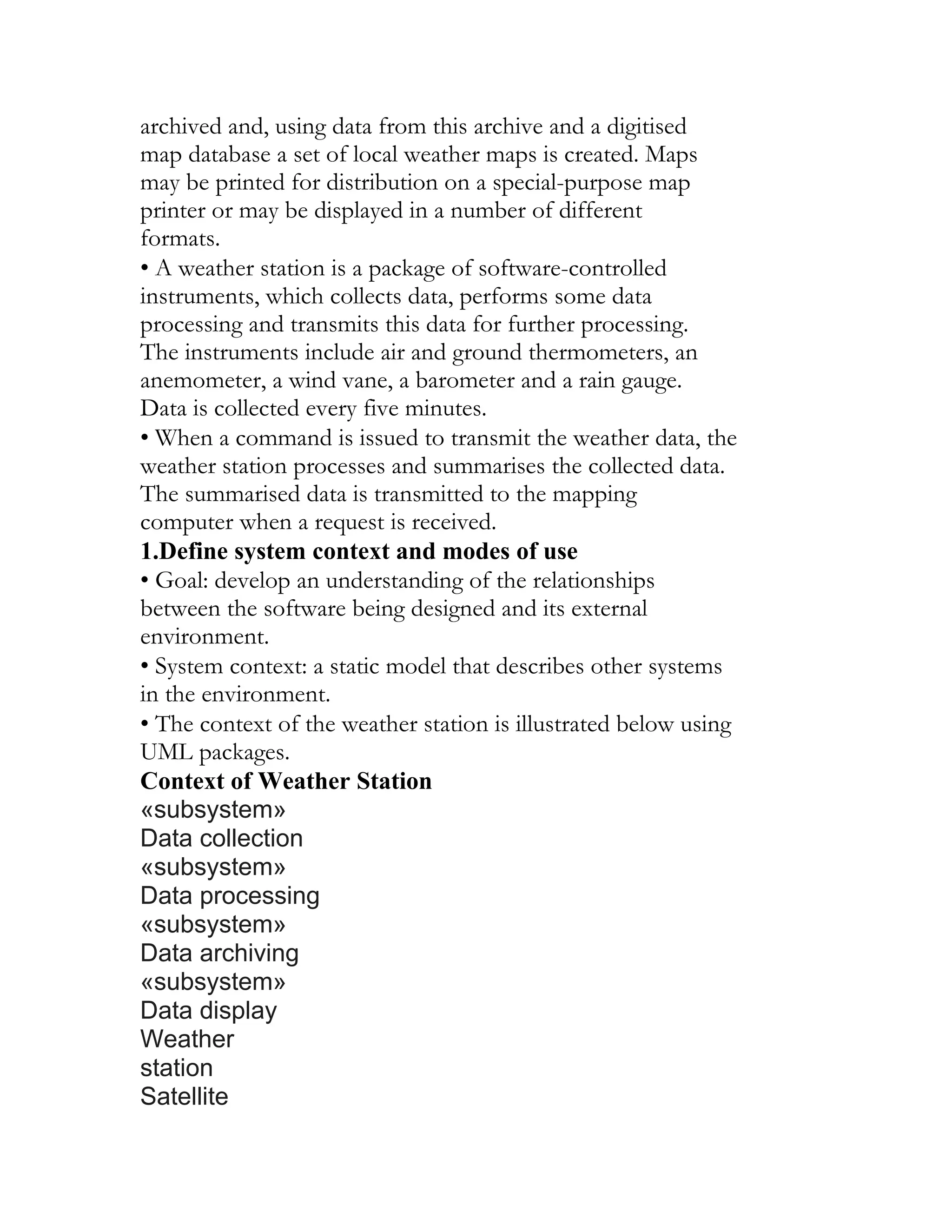
![specifications
These are notations based on mathematical concepts
such as finite-state machines or sets. These unambiguous
specifications reduce the arguments between customer
and contractor about system functionality. However, most
customers don’t understand formal specifications and are
reluctant to accept it as a system contract. I discuss formal
specification in Chapter 9.
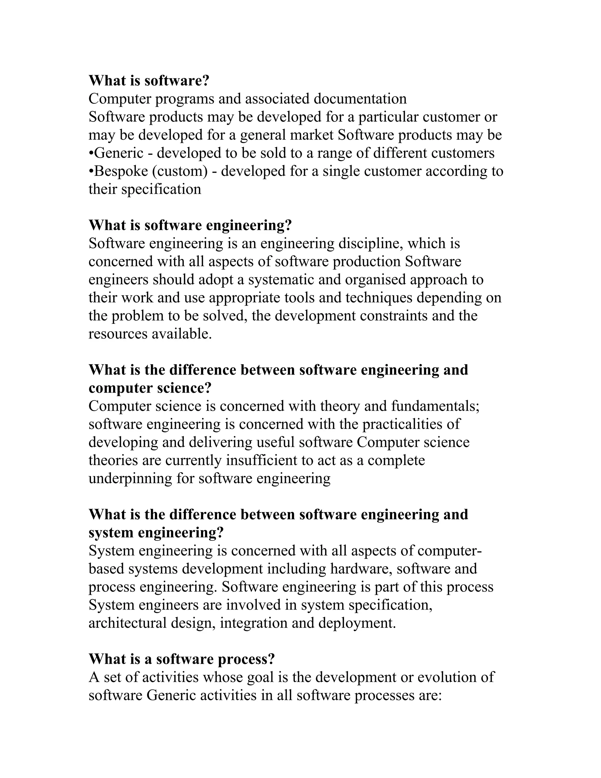
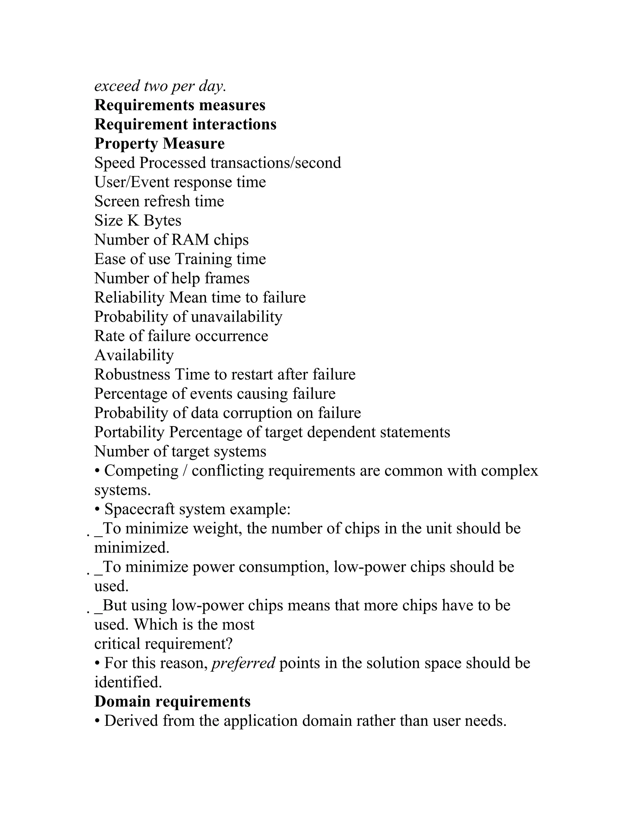
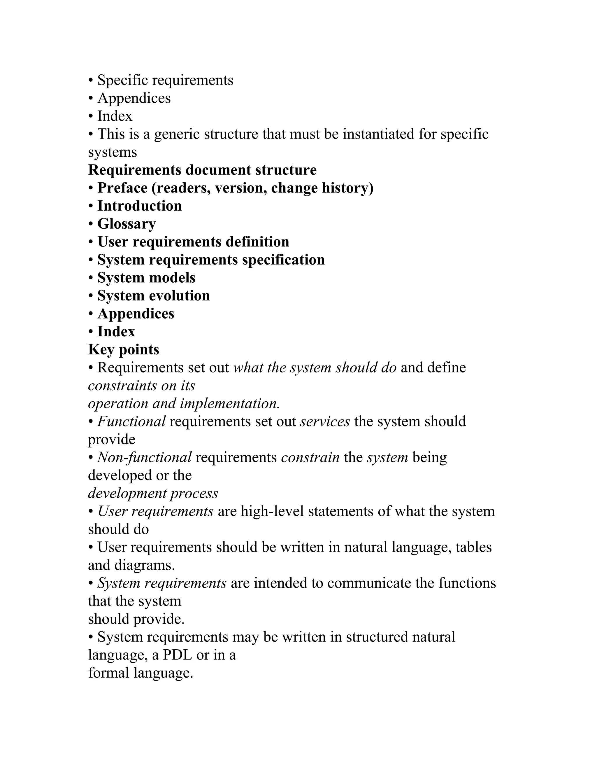
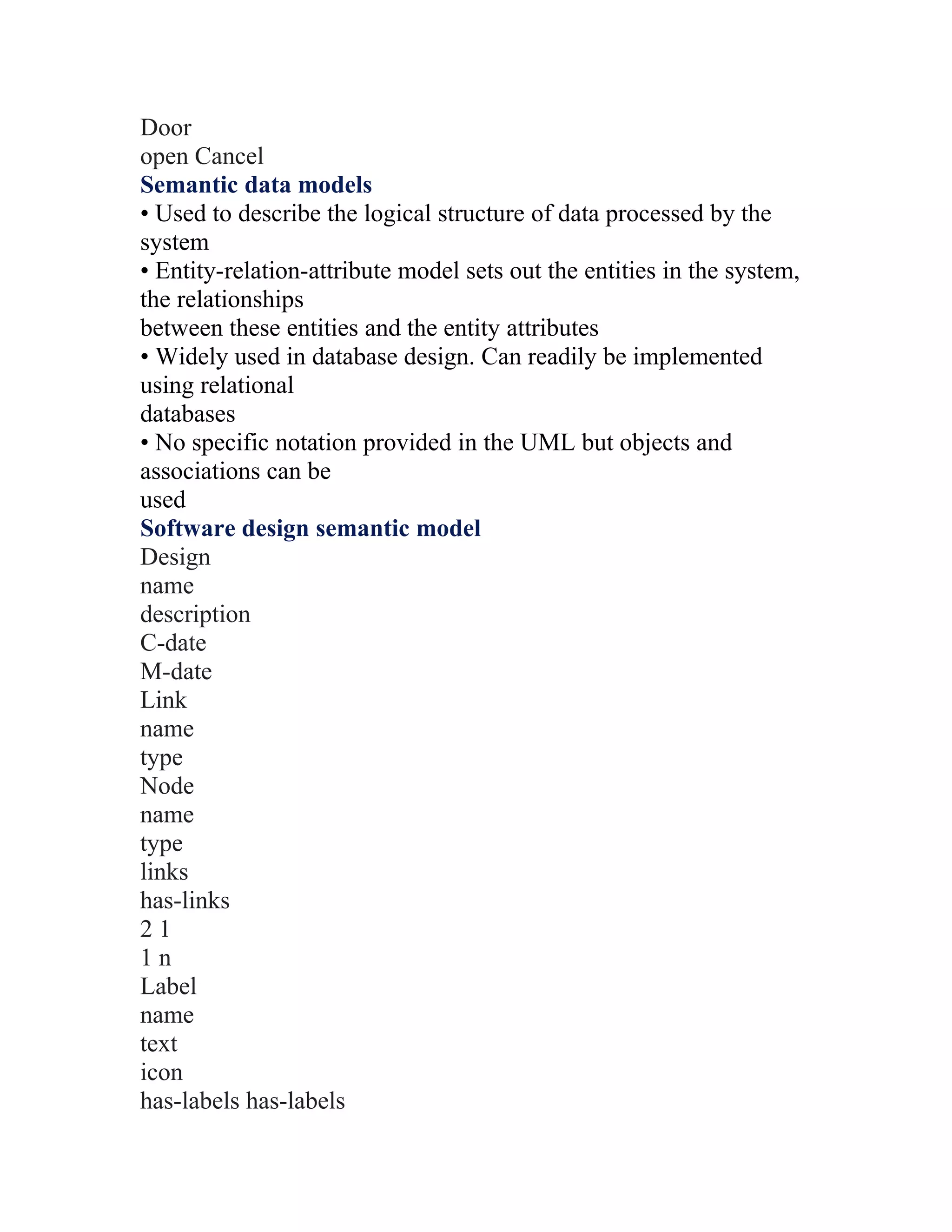
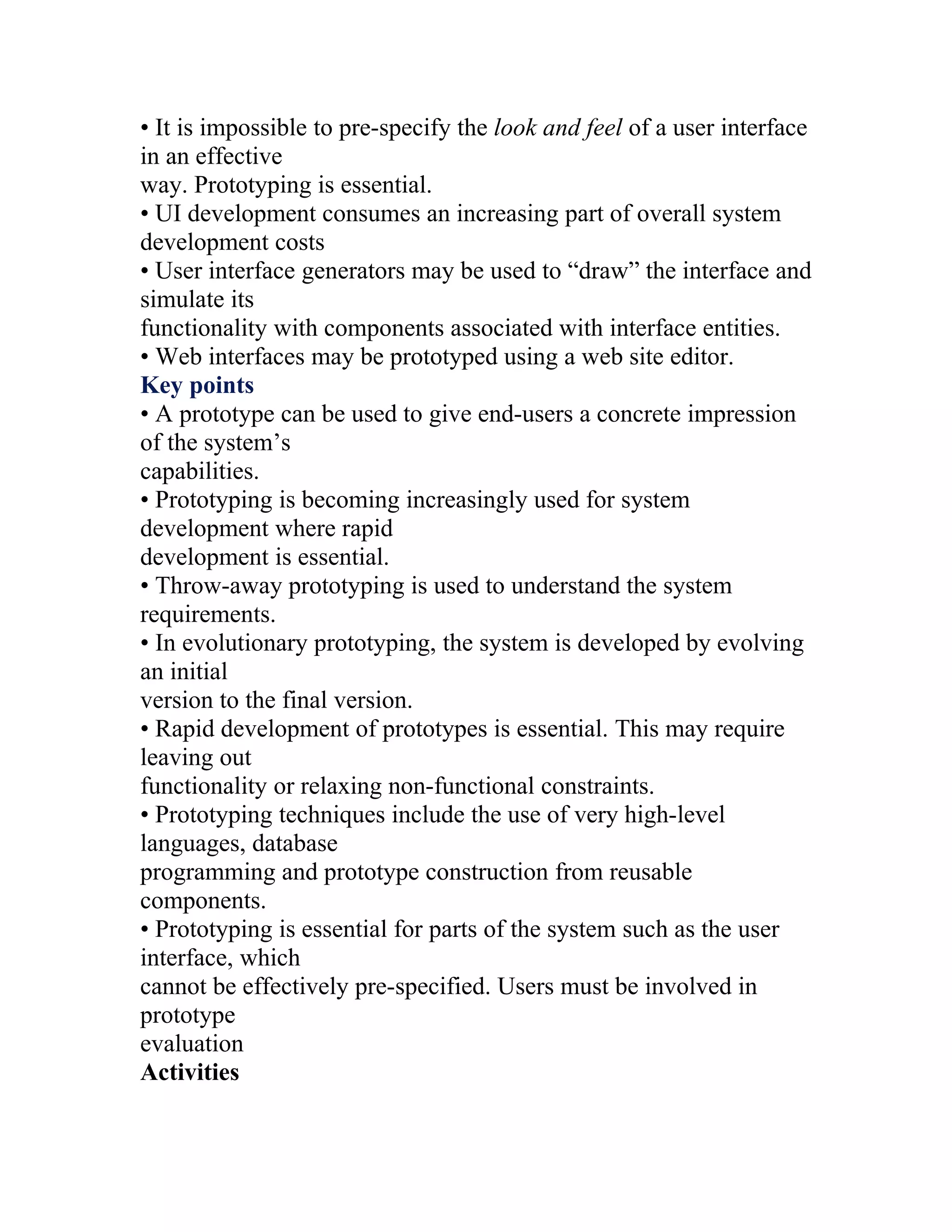
Program Description Languages (PDLs)
• Requirements are specified operationally using pseudo-code.
• Shows what is required by illustrating how the requirements
could be satisfied.
• Especially useful when specifying a process that involves an
ordered sequence of
actions, or when describing hardware and software interfaces.
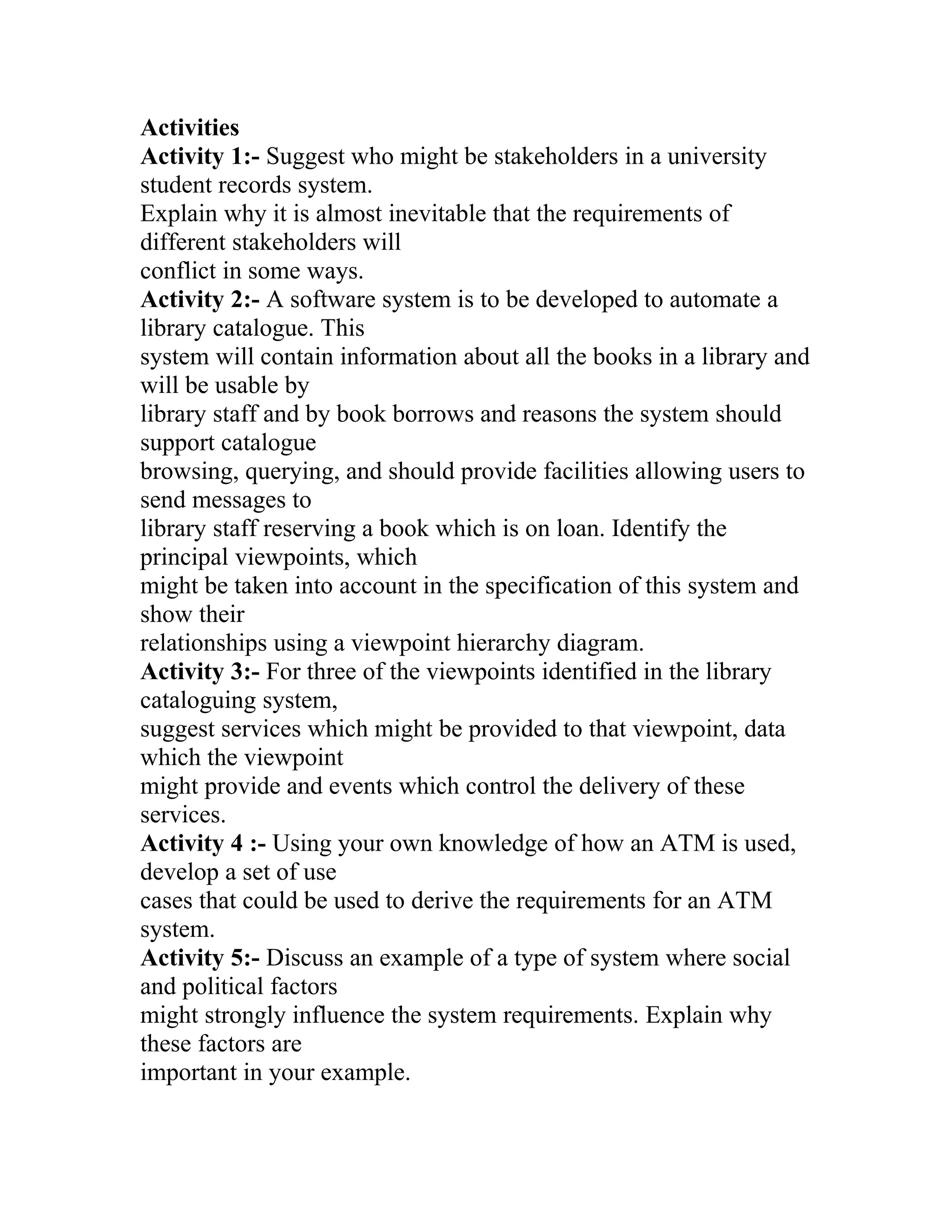
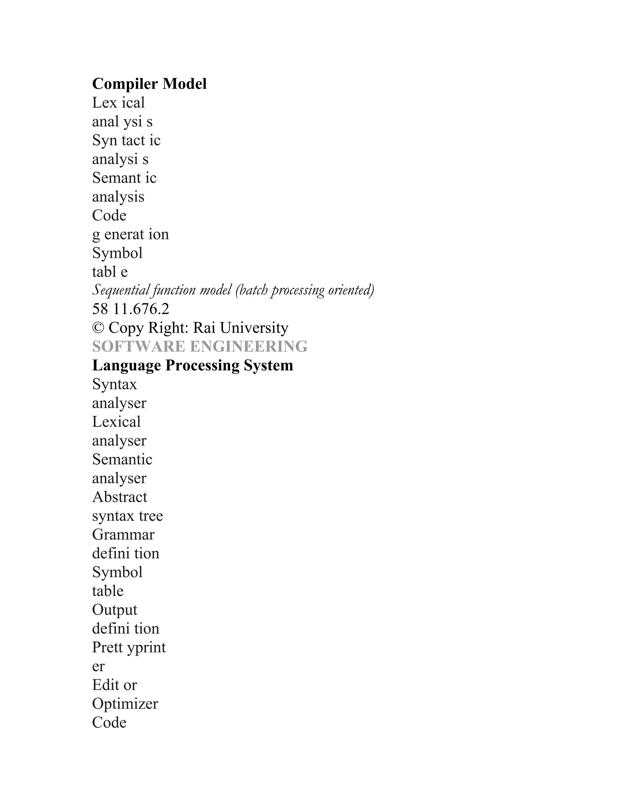
Part of an ATM specification
class ATM {
// declarations here
public static void main (String args[]) throws InvalidCard {
try {
thisCard.read () ; // may throw InvalidCard exception
pin = KeyPad.readPin () ; attempts = 1 ;
while ( !thisCard.pin.equals (pin) & attempts < 4 )
{ pin = KeyPad.readPin () ; attempts = attempts + 1 ;
}
if (!thisCard.pin.equals (pin))
throw new InvalidCard ("Bad PIN");
thisBalance = thisCard.getBalance () ;
do { Screen.prompt (" Please select a service ") ;
service = Screen.touchKey () ;
switch (service) {
case Services.withdrawalWithReceipt:
receiptRequired = true ;
PDL disadvantages](https://image.slidesharecdn.com/s1-120529084210-phpapp02/75/SOFTWARE-ENGINEERING-43-2048.jpg)
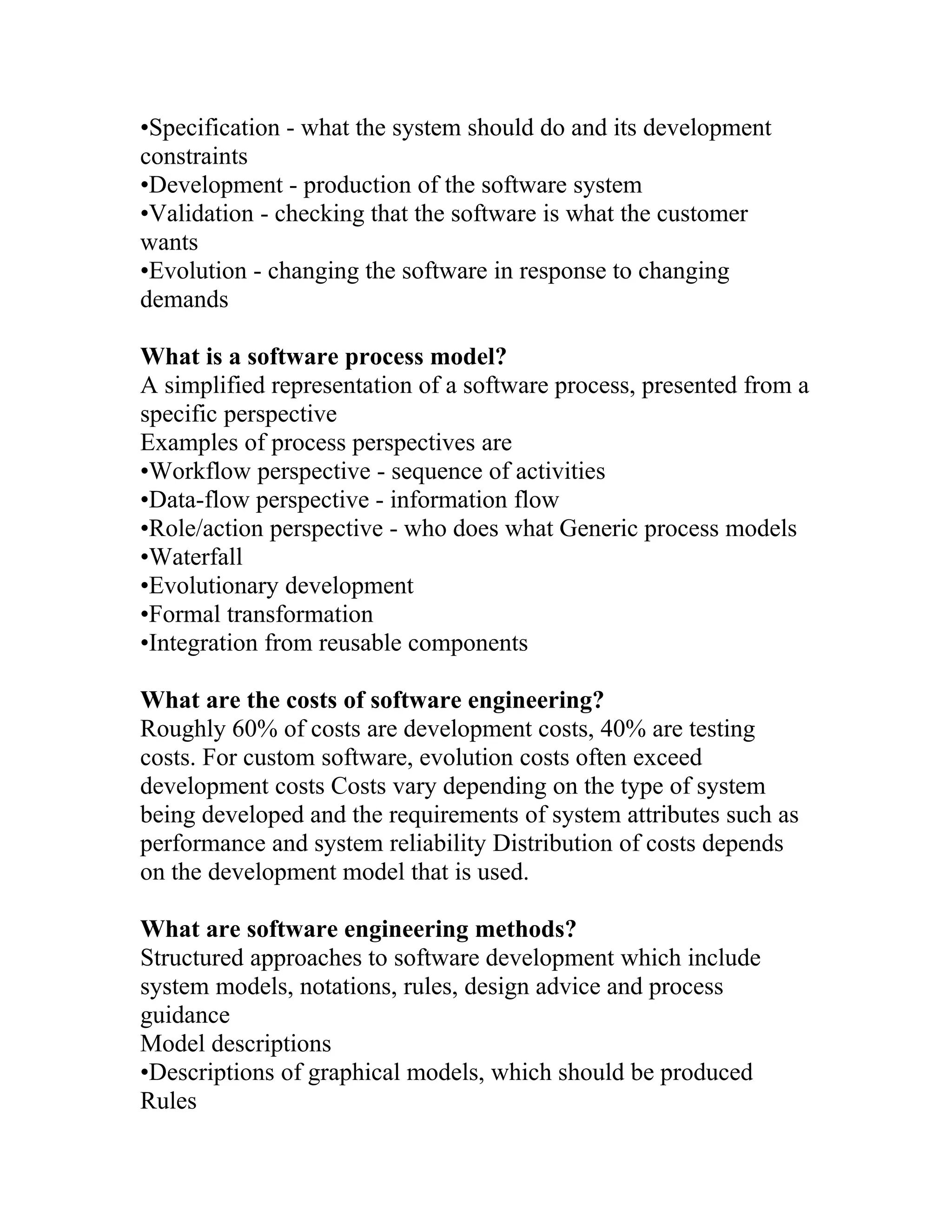
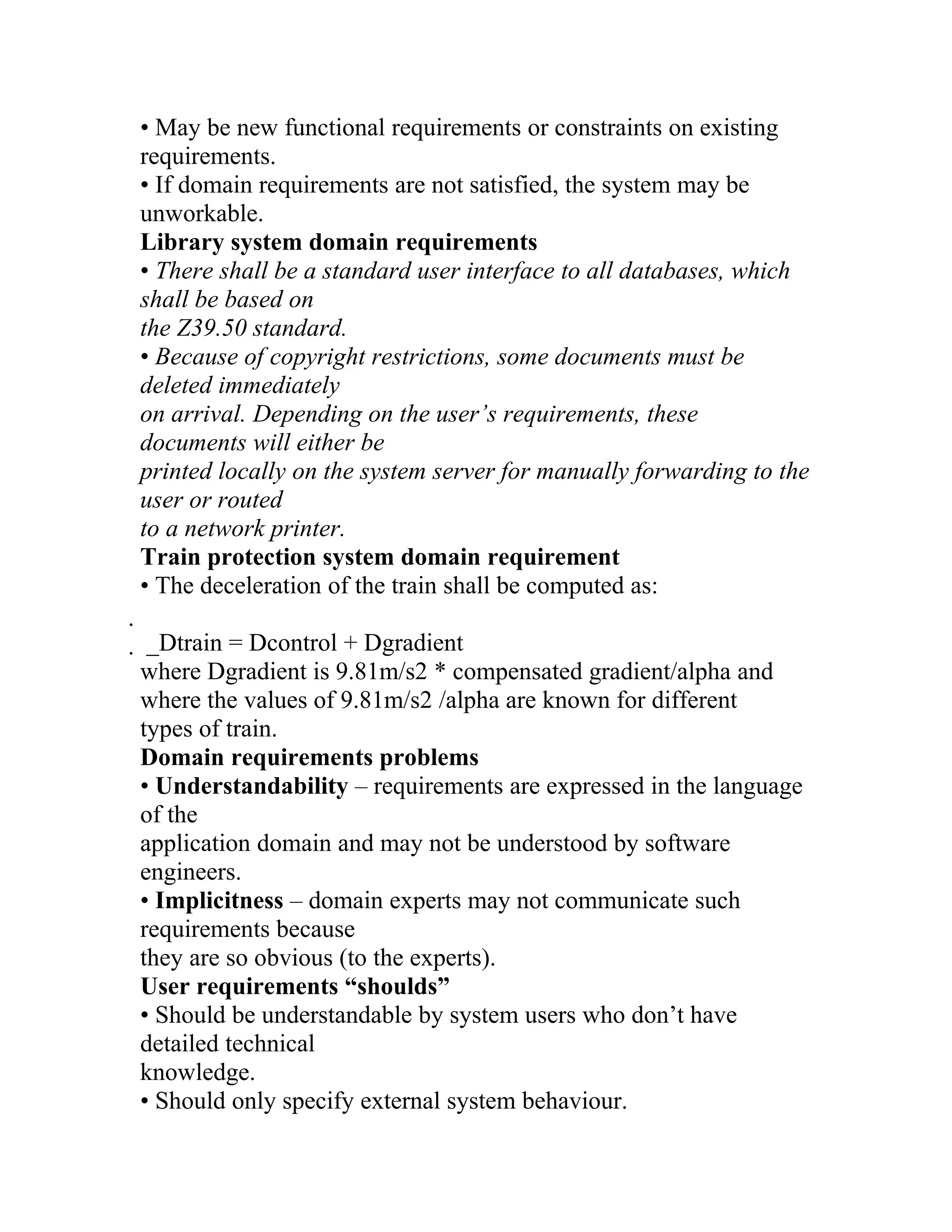
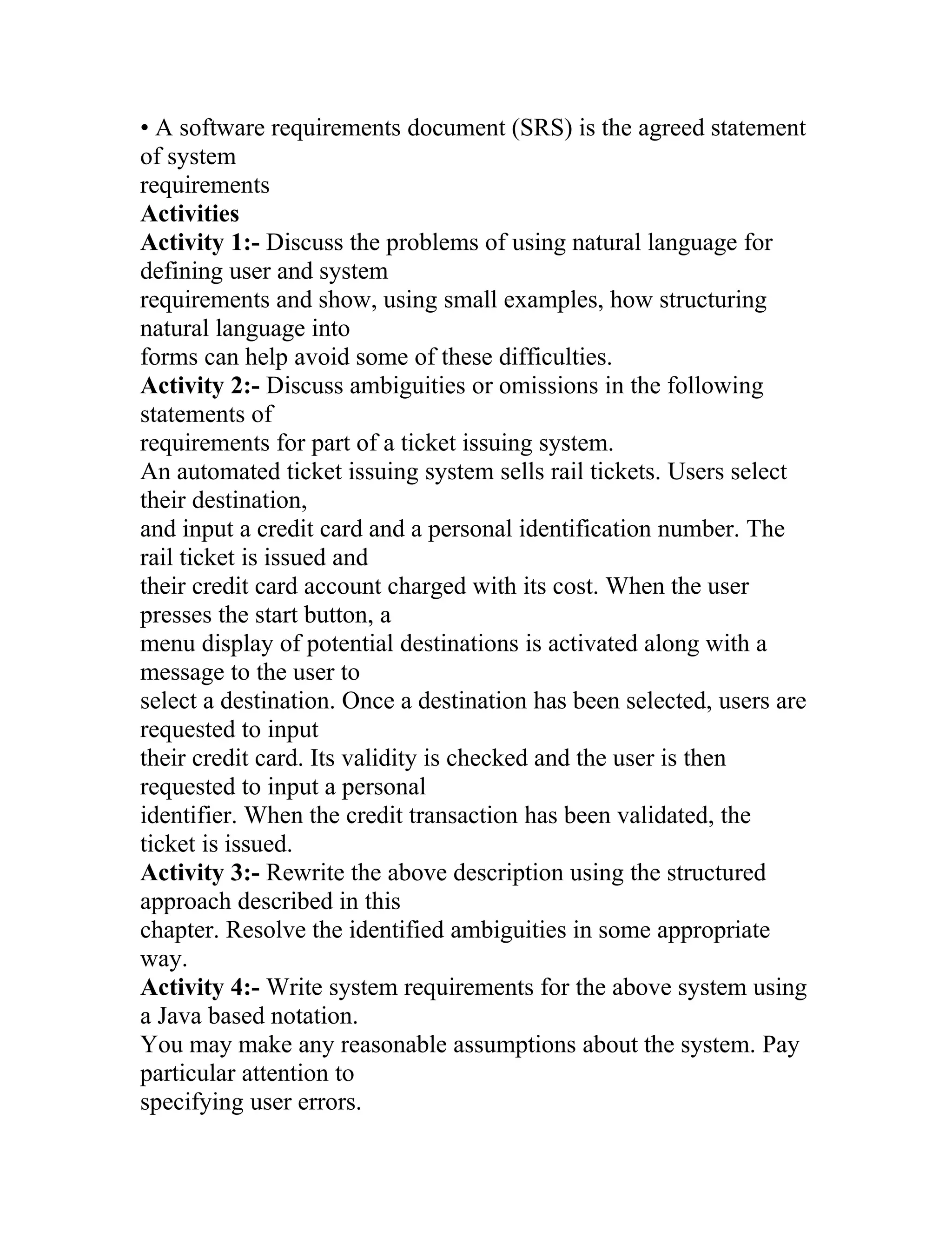
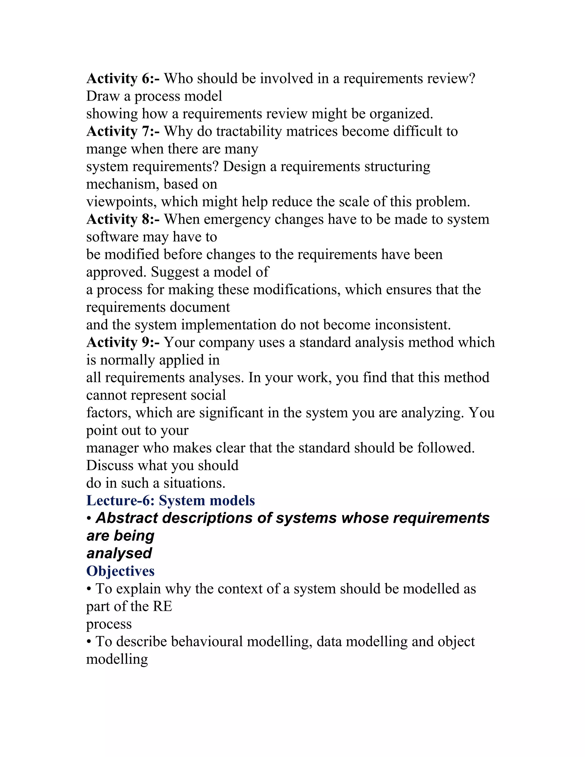
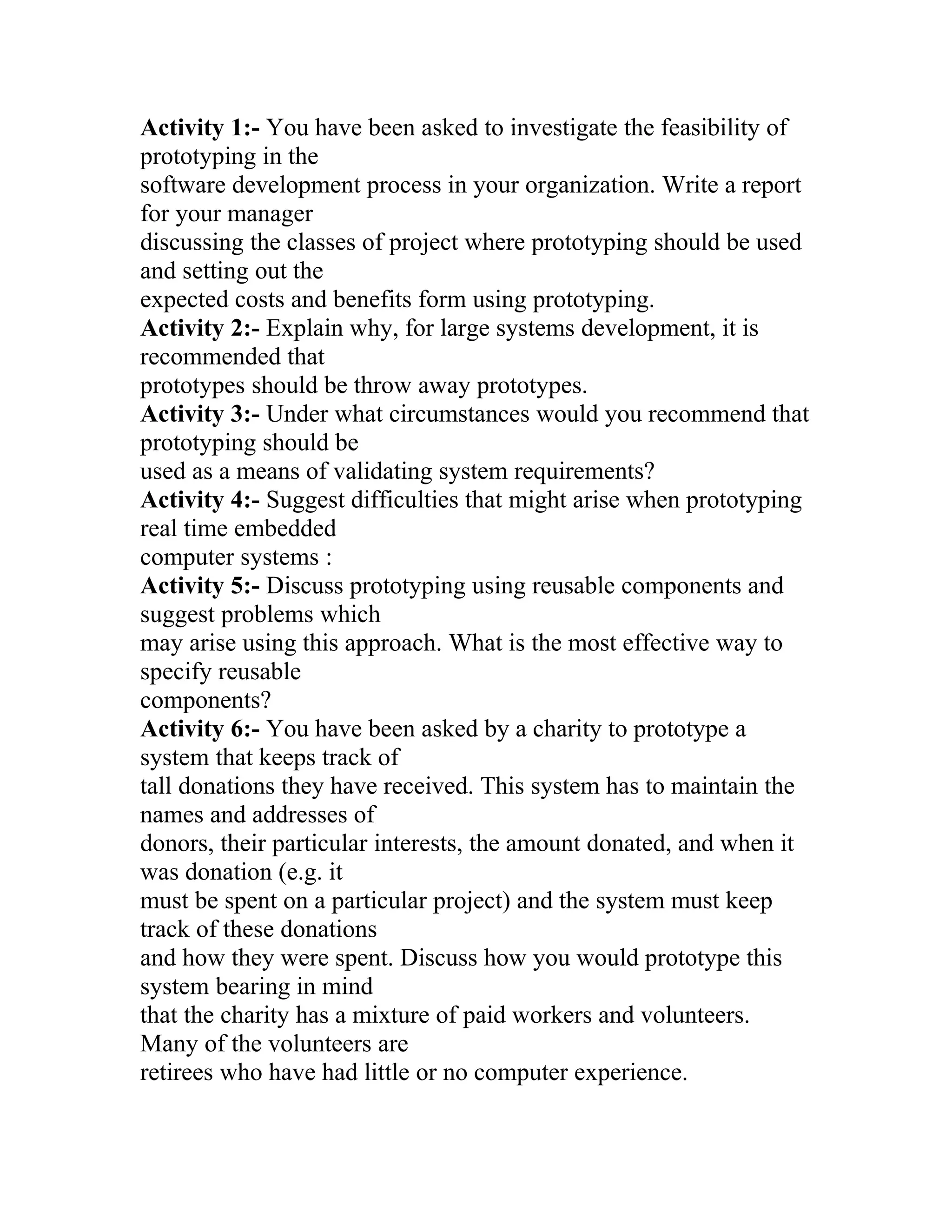
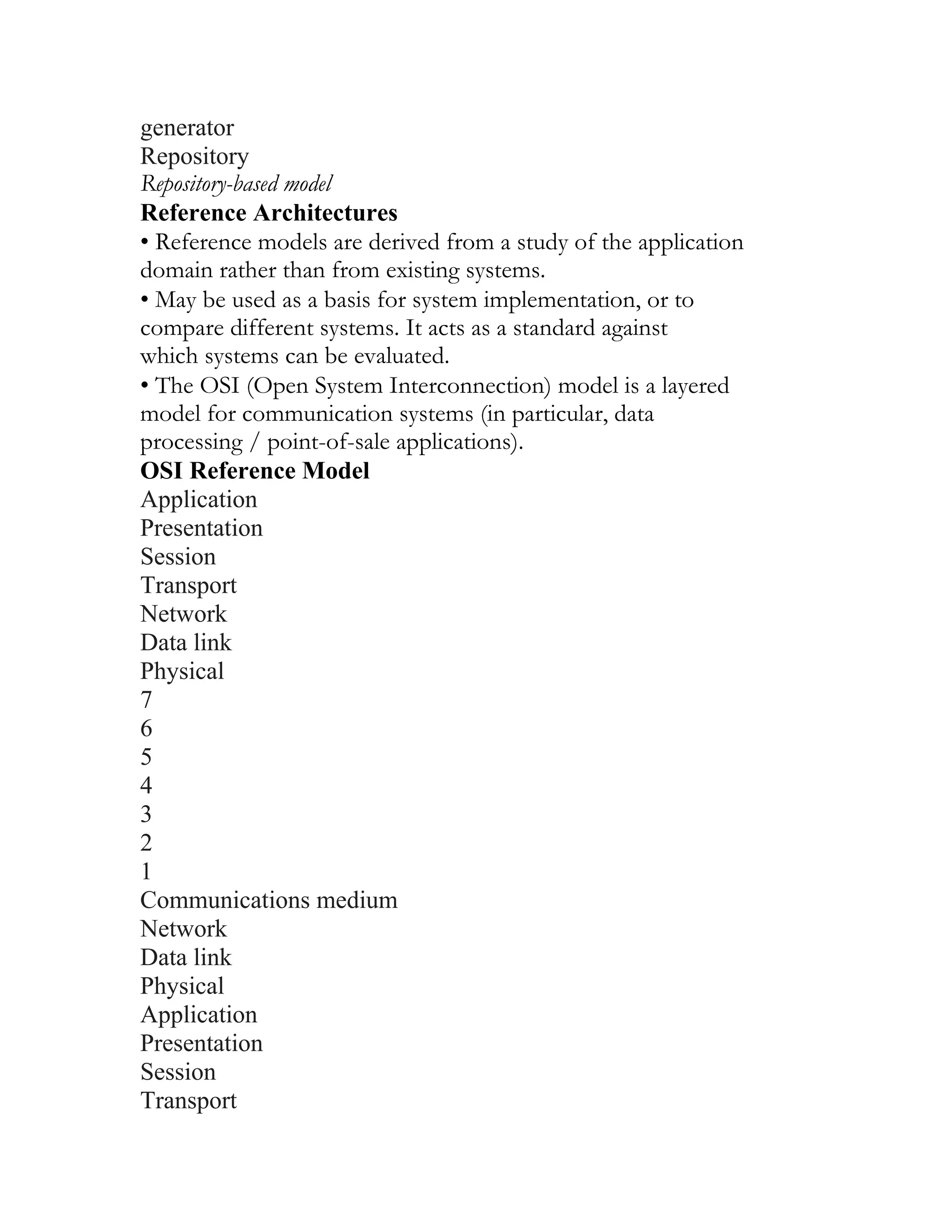
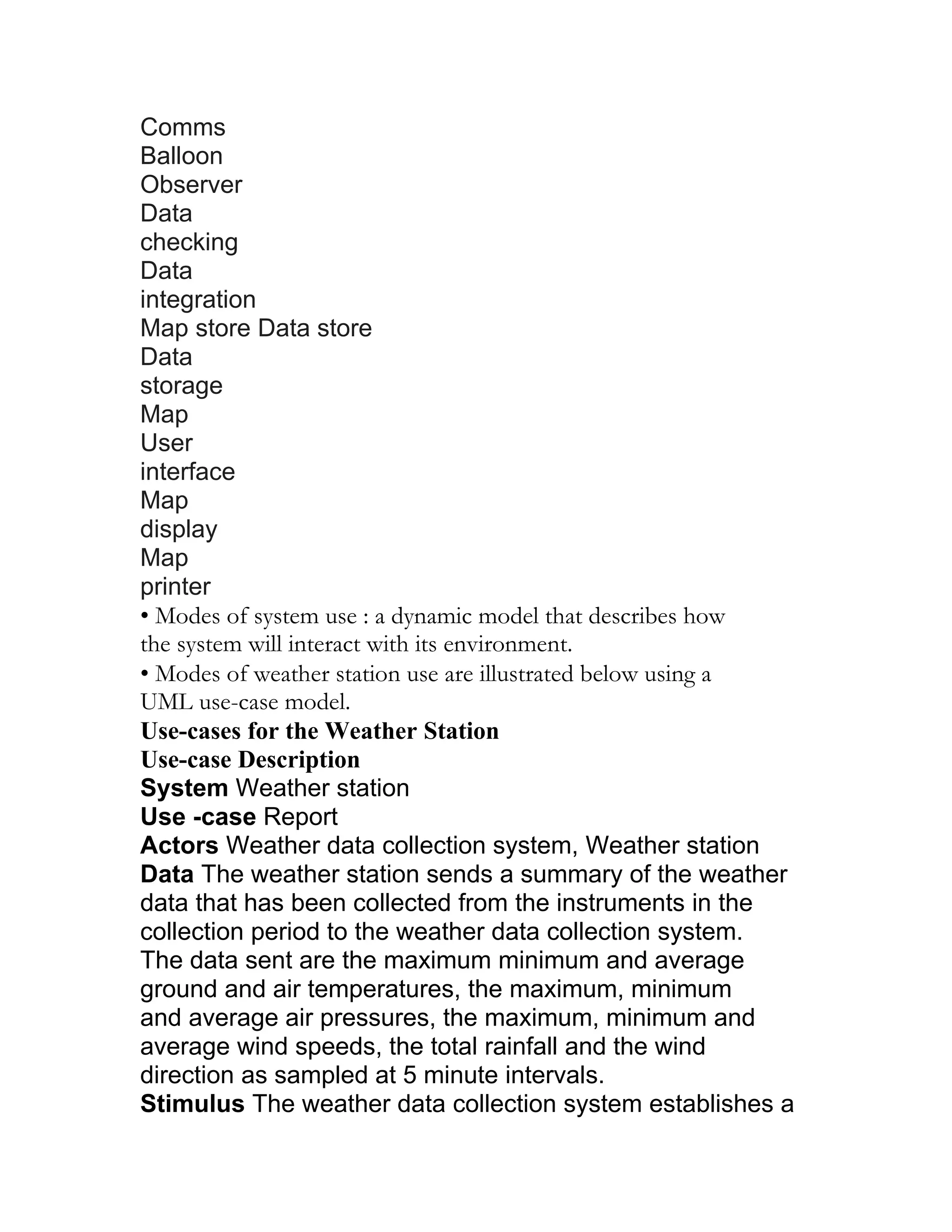
![• PDL may not be sufficiently expressive to illustrate requirements
in a concise an
understandable way.
• Notation is only understandable to people with programming
language
knowledge.
• The specification may be taken as a design prescription rather
than a model to
facilitate requirements understanding.
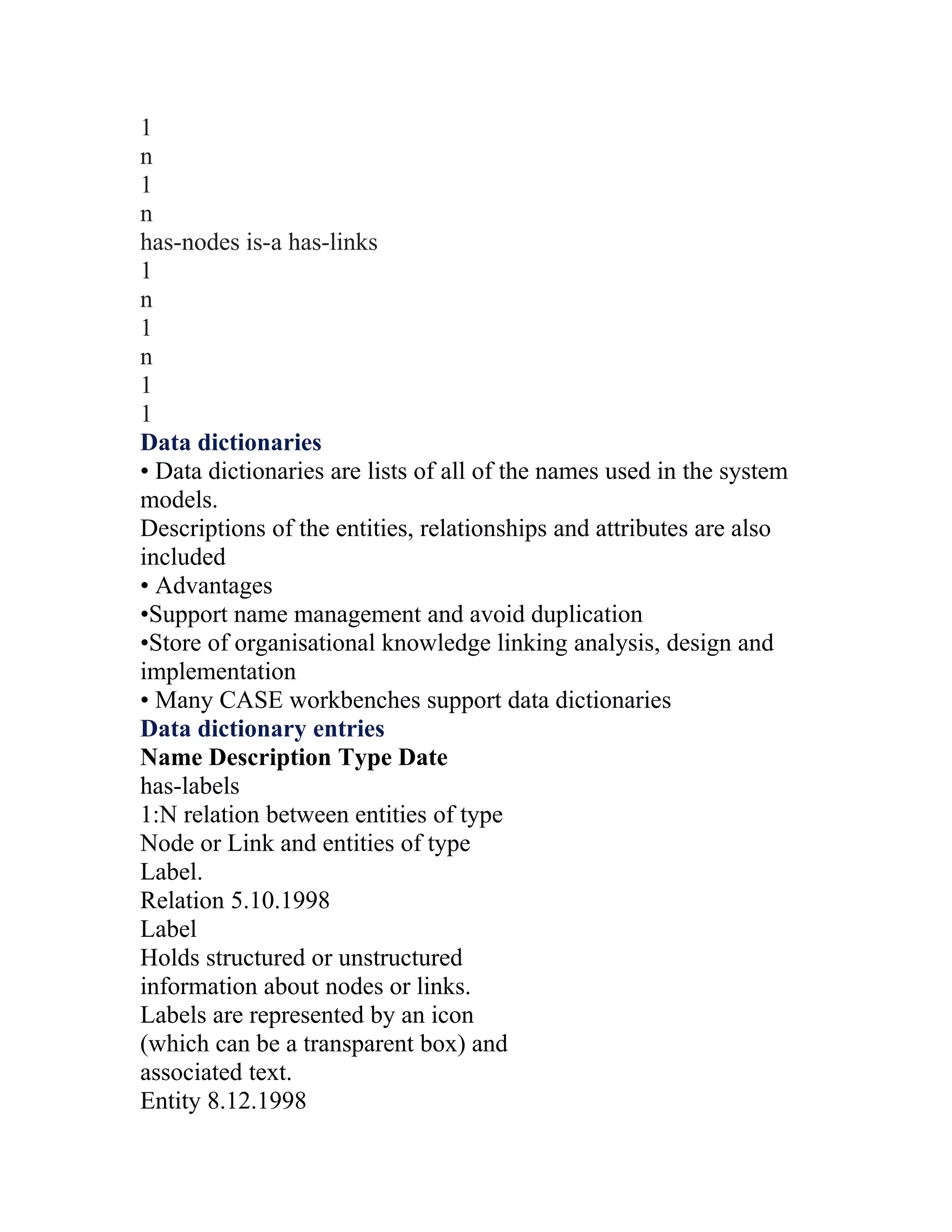
Interface specification
• Used to specify operating interfaces with other systems.
_Procedural interfaces
_Data structures that are exchanged
_Data representations
• Also used to specify functional behaviour.
• Formal notations are effective for interface specification – e.g.,
pre- and postconditions
PDL interface description
Example: interface and operational specifications of a function
interface PrintServer {
// defines an abstract printer server
// requires: interface Printer, interface PrintDoc
// provides: initialize, print, displayPrintQueue,
cancelPrintJob, switchPrinter
void initialize ( Printer p ) ;
void print ( Printer p, PrintDoc d ) ;
void displayPrintQueue ( Printer p ) ;
void cancelPrintJob (Printer p, PrintDoc d) ;
void switchPrinter (Printer p1, Printer p2, PrintDoc d) ;
} //PrintServer
Function: Set BIG to the largest value in array A [1.. N]
Interface specification:
pre-condition: N ≥ 1
post-condition: there exists an i in [1,N] such that BIG=A [i] &
for every in](https://image.slidesharecdn.com/s1-120529084210-phpapp02/75/SOFTWARE-ENGINEERING-44-2048.jpg)
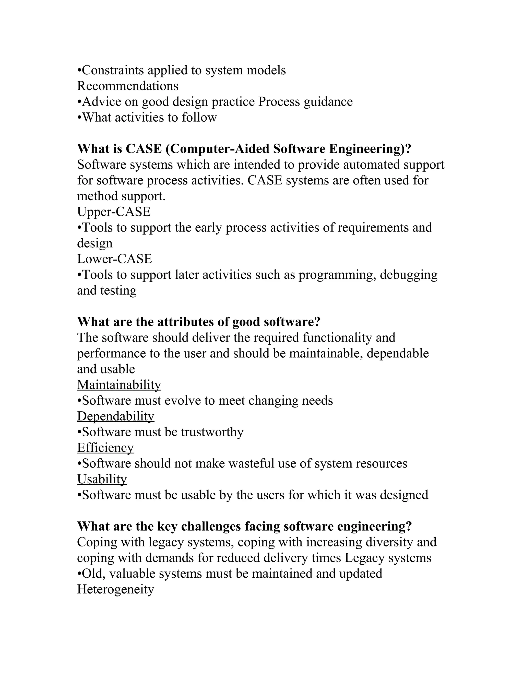
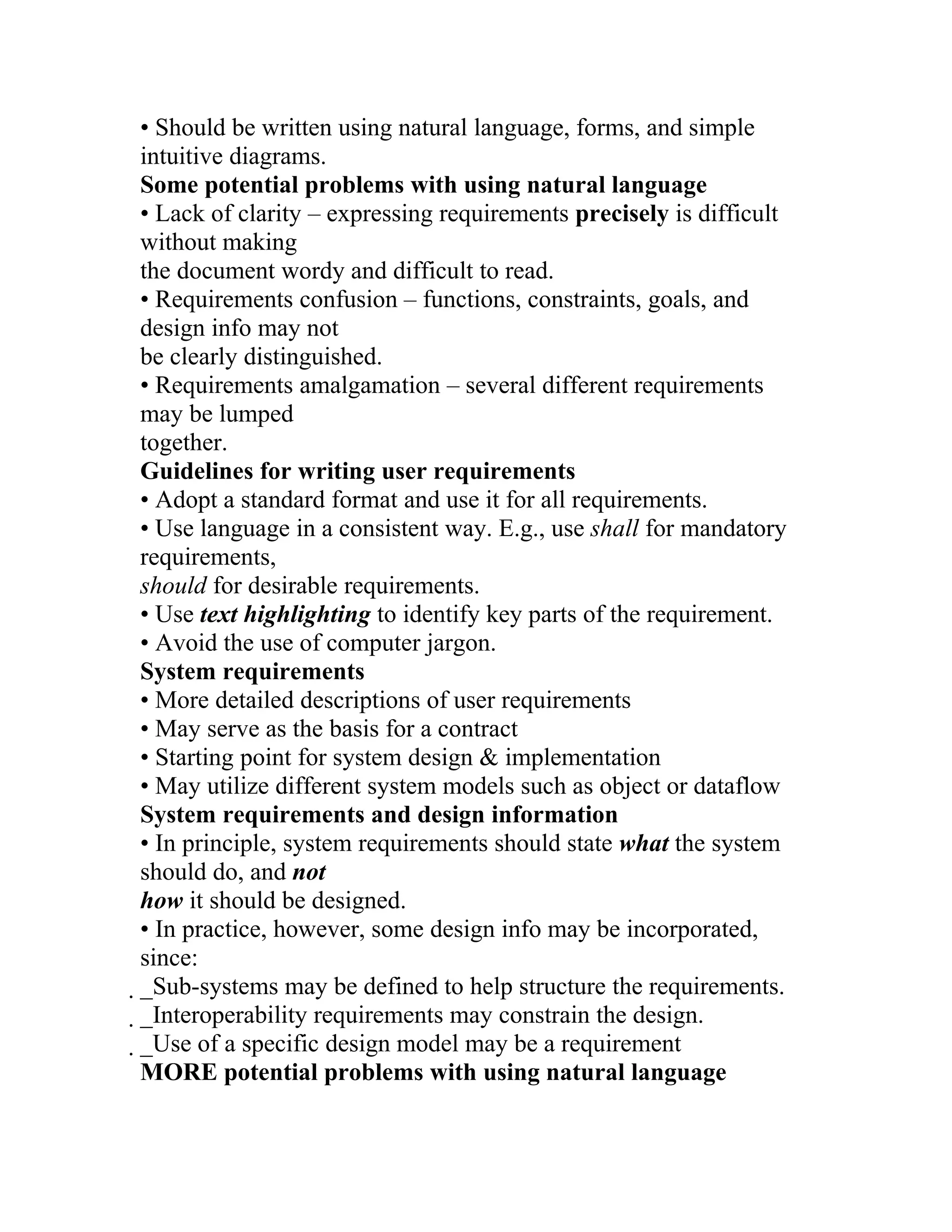
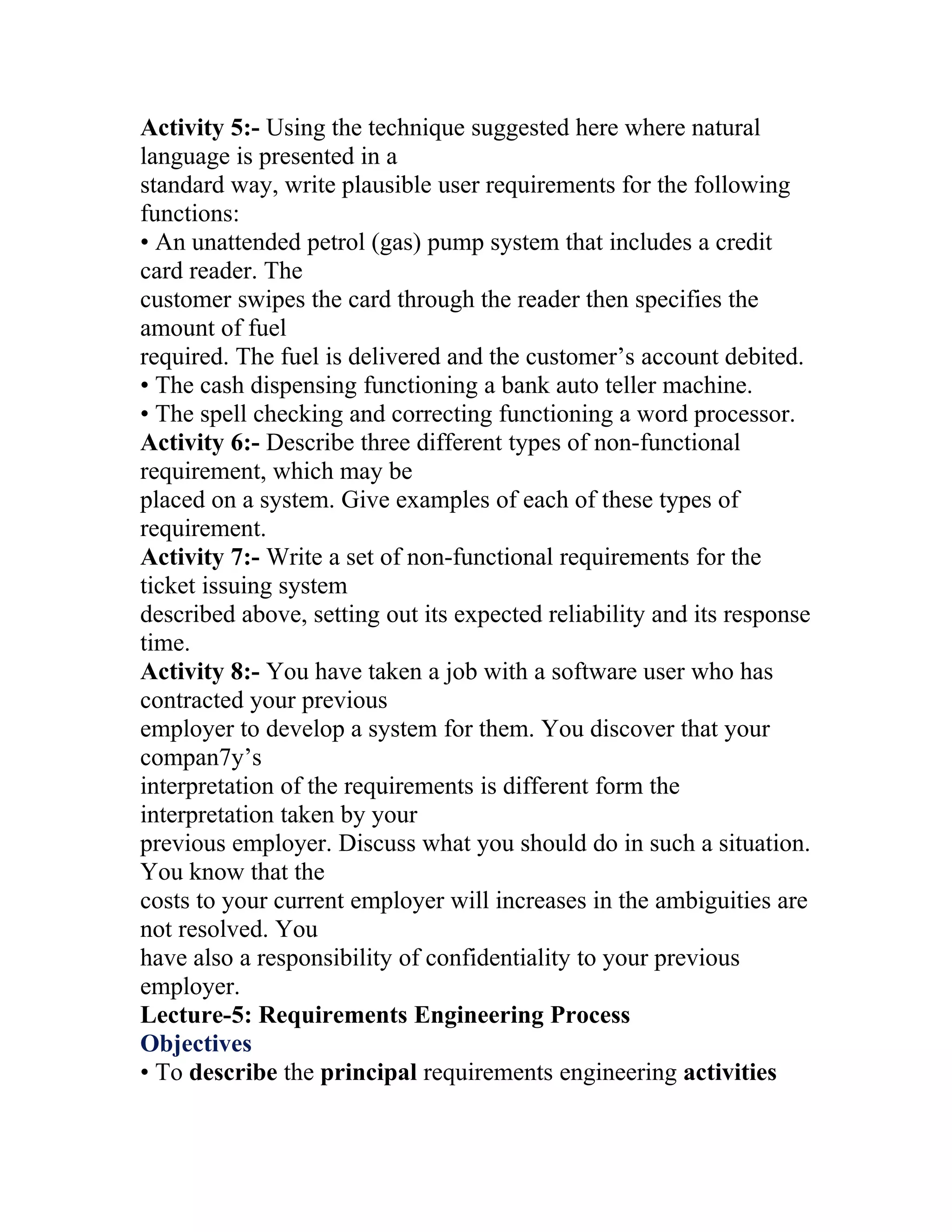
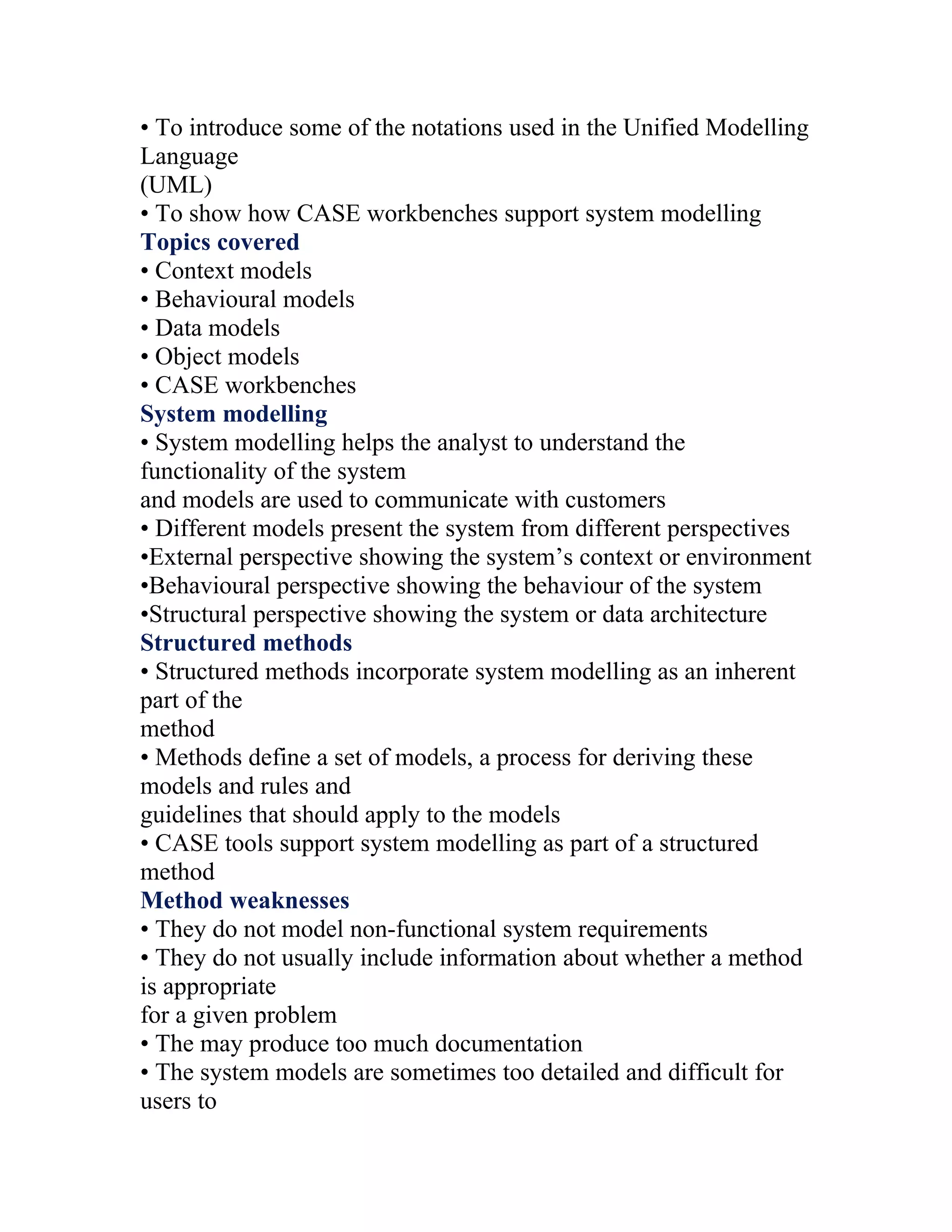
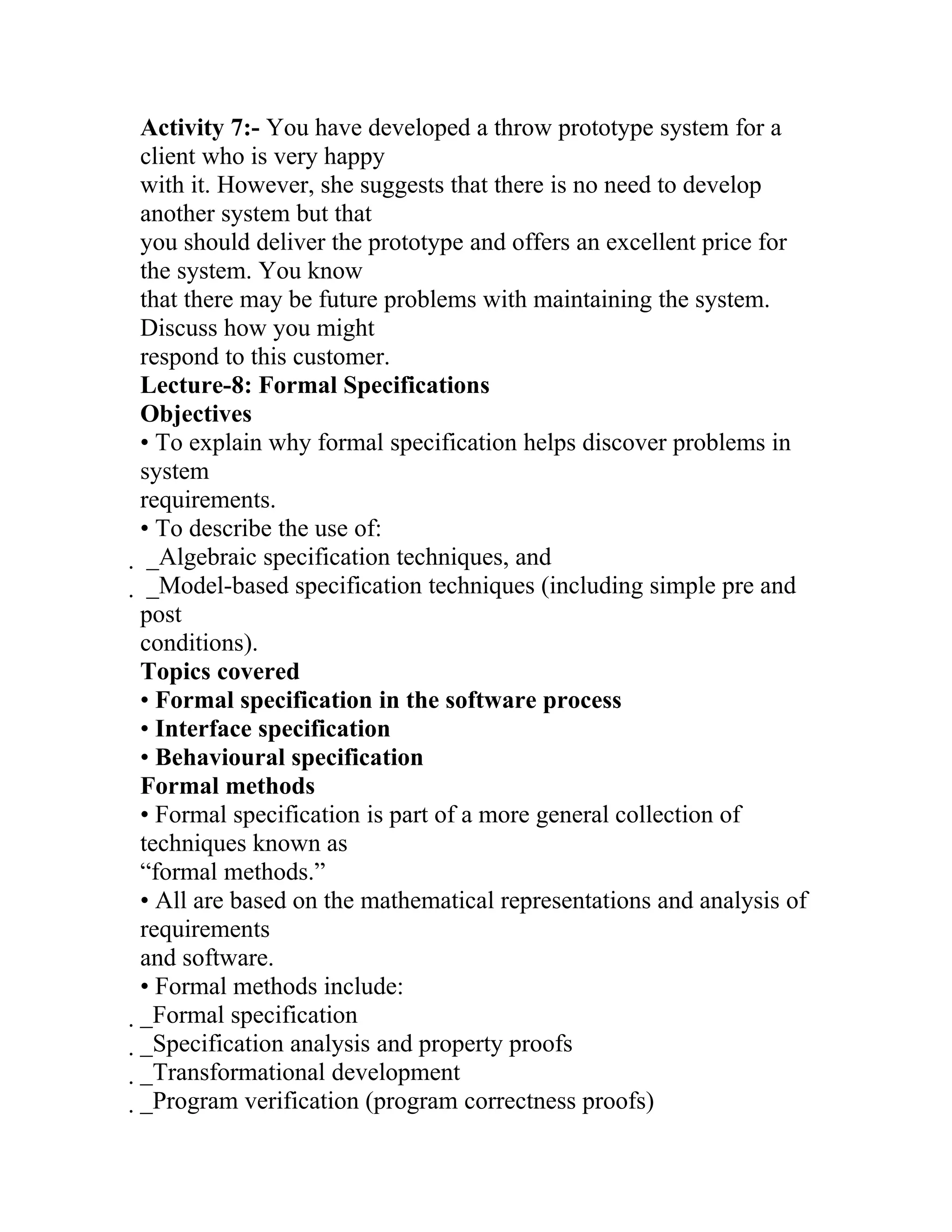
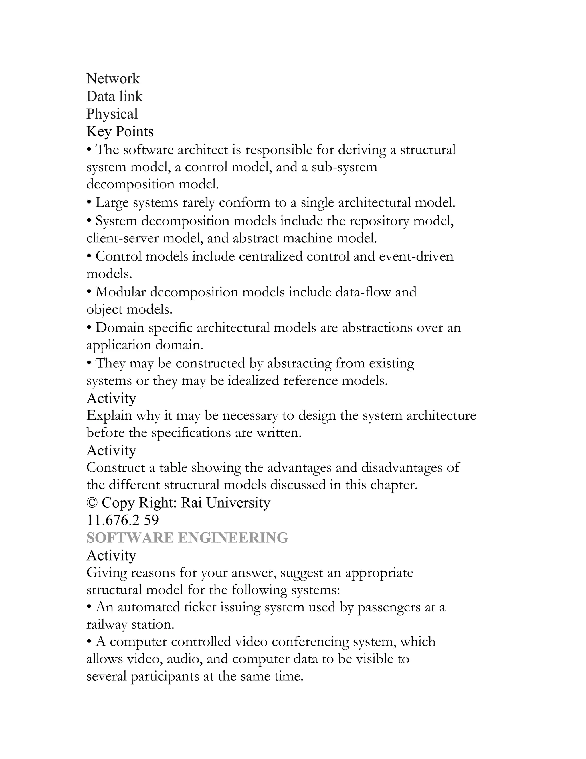
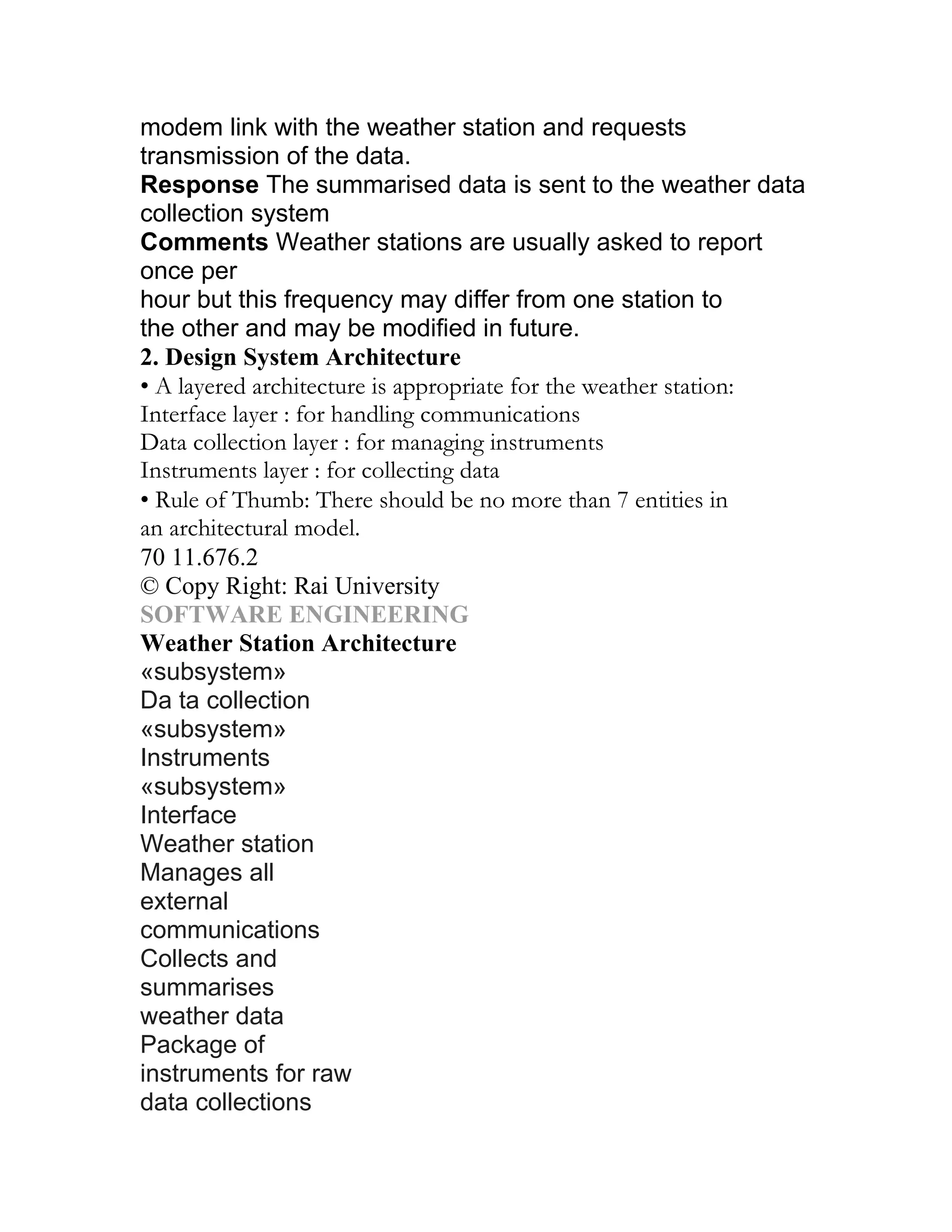
![[1,N], BIG ≥ A [j] & A is unchanged
Operational specification:
if N ≥ 1 then do
BIG: = A [1]
for i = 2 to N do
if A [i] > BIG then BIG: = A [i] end if
end for
end if
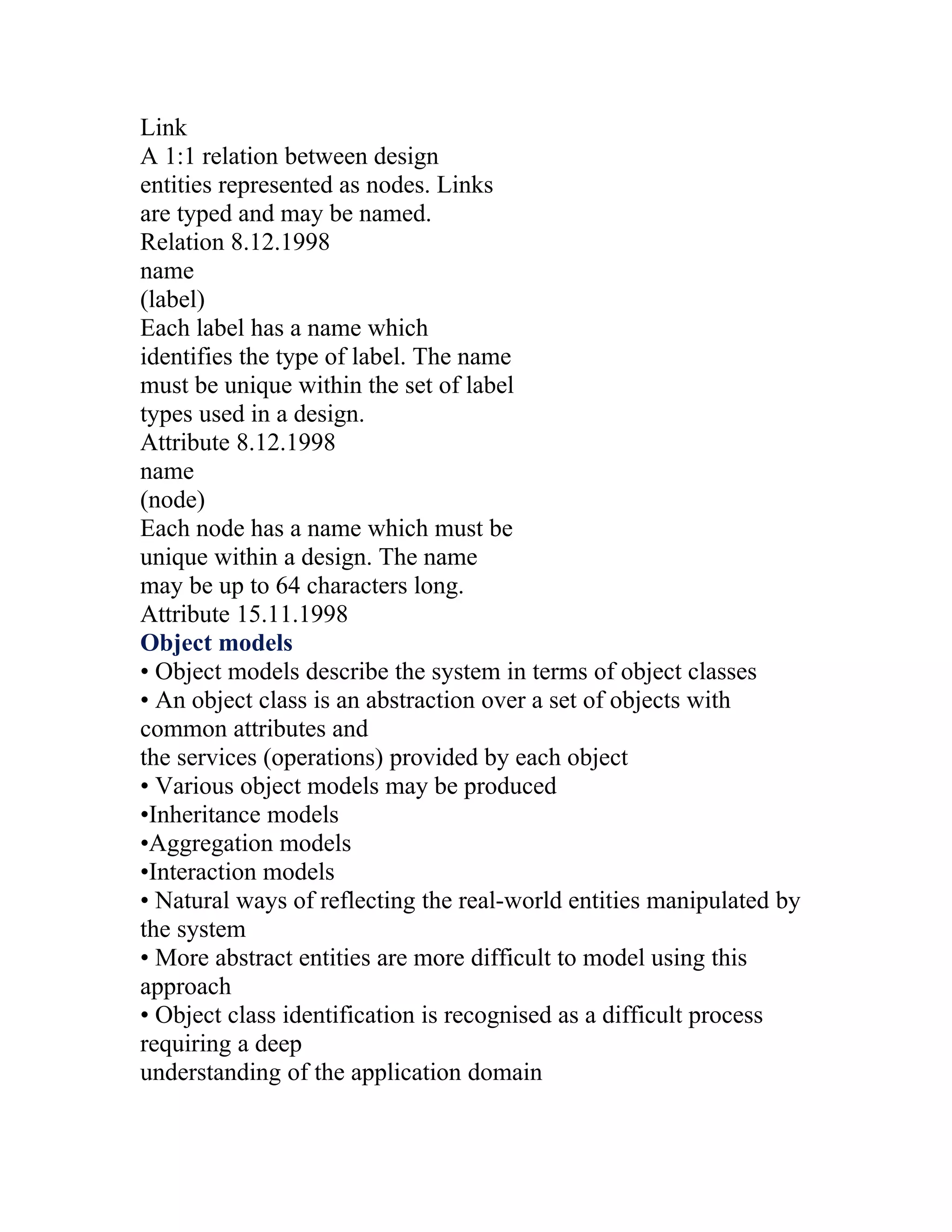
The requirements document (SRS)
• The official statement of what is required of the system
developers.
• Should include both user and system requirements.
• NOT a design document. As much as possible, it should set out
WHAT the
system should do rather than HOW it should do it.
Users of a requirements document
Us e t he req ui rem ent s
d oc um e n t to pl a n a bi d for
S peci fy t he req uirem en ts and
read th em to c h eck t ha t t hey
m e e t th e ir n eeds . Th ey
s pe c ify c h ang es to th e
requ irem en ts
S y stem c us to m e rs
Requirements document requirements
• Specify external system behaviour
• Specify implementation constraints
• Easy to change (!)
• Serve as reference tool for maintenance
• Record forethought about the life cycle of the system i.e. predict
changes
• Characterise responses to unexpected events
IEEE requirements standard
• Introduction
• General description](https://image.slidesharecdn.com/s1-120529084210-phpapp02/75/SOFTWARE-ENGINEERING-45-2048.jpg)
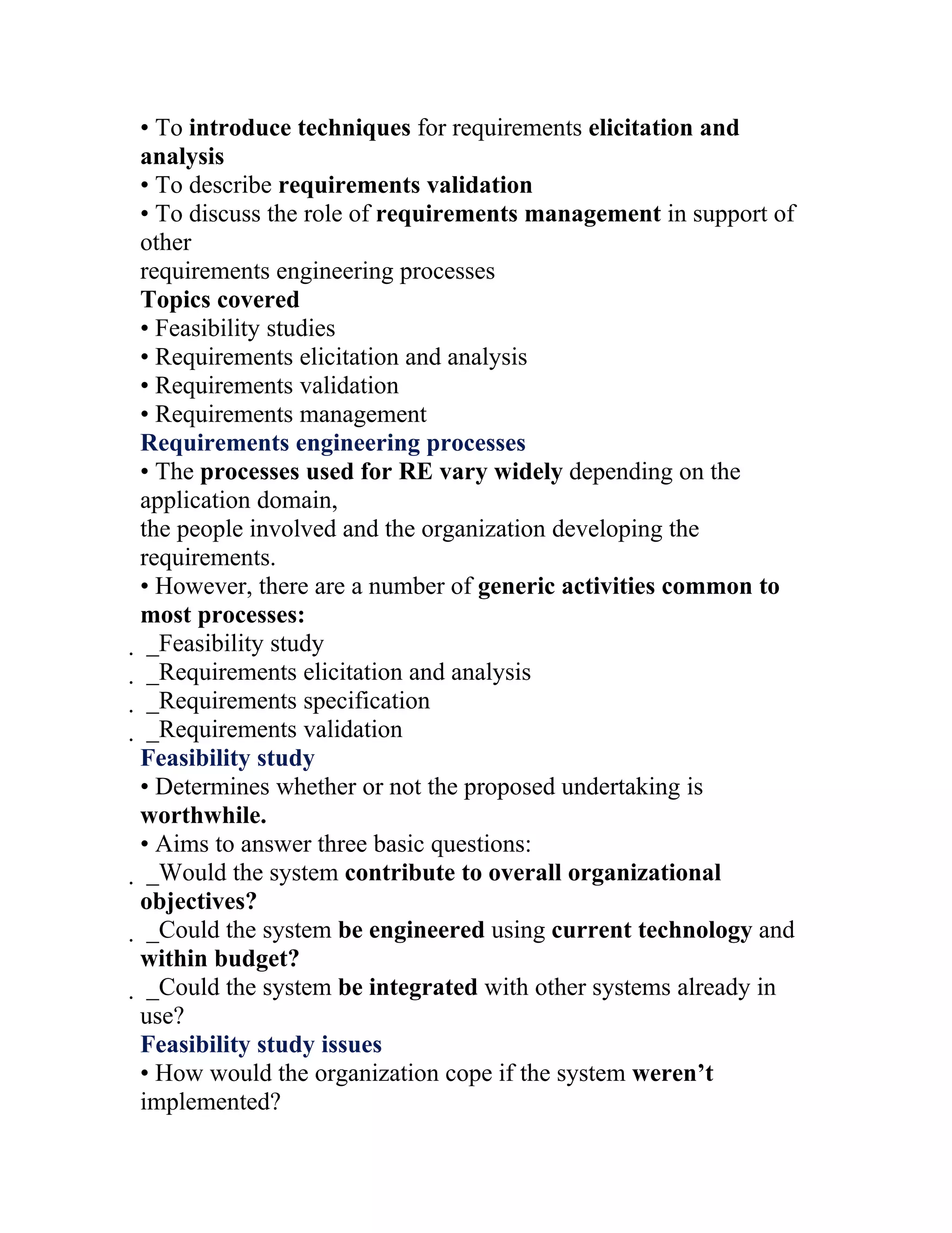
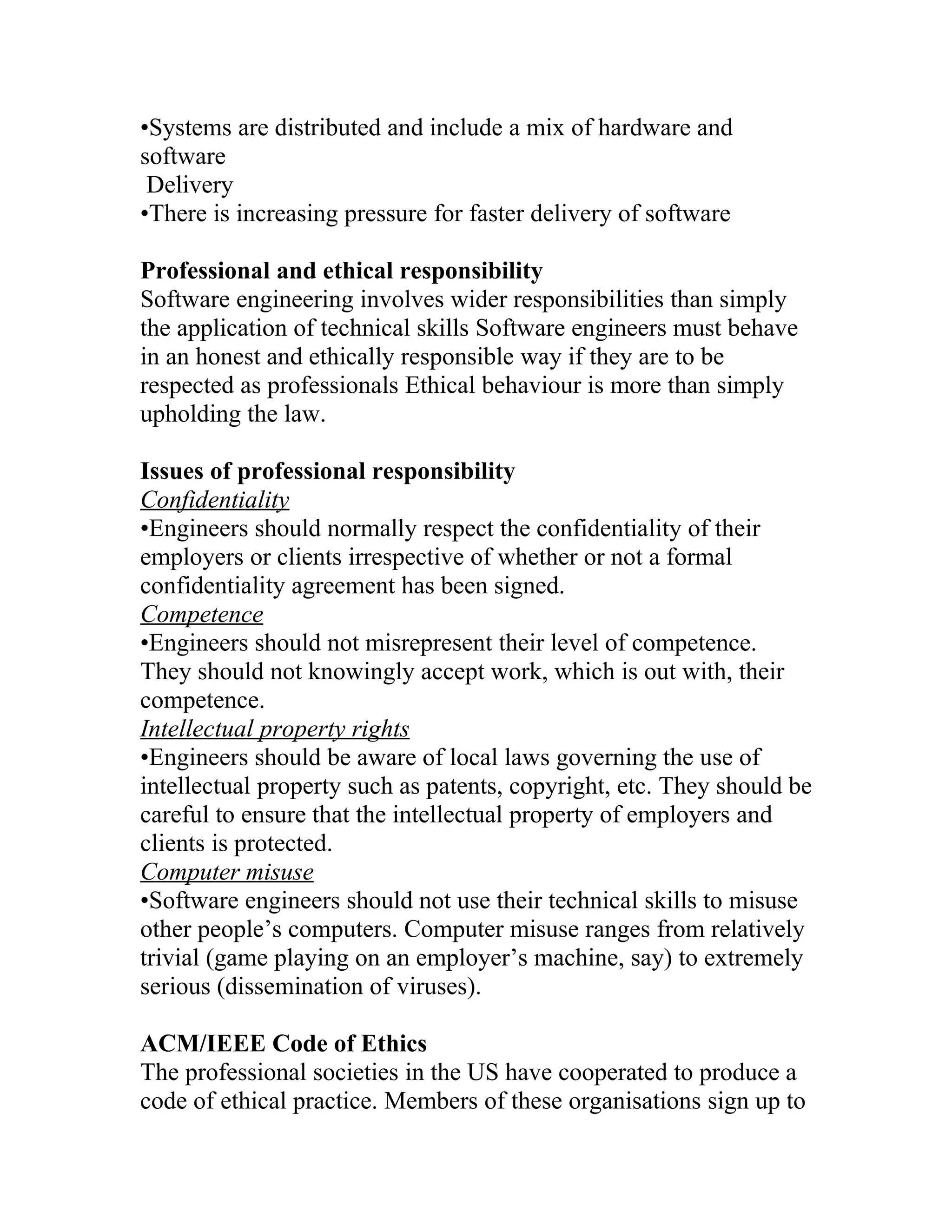
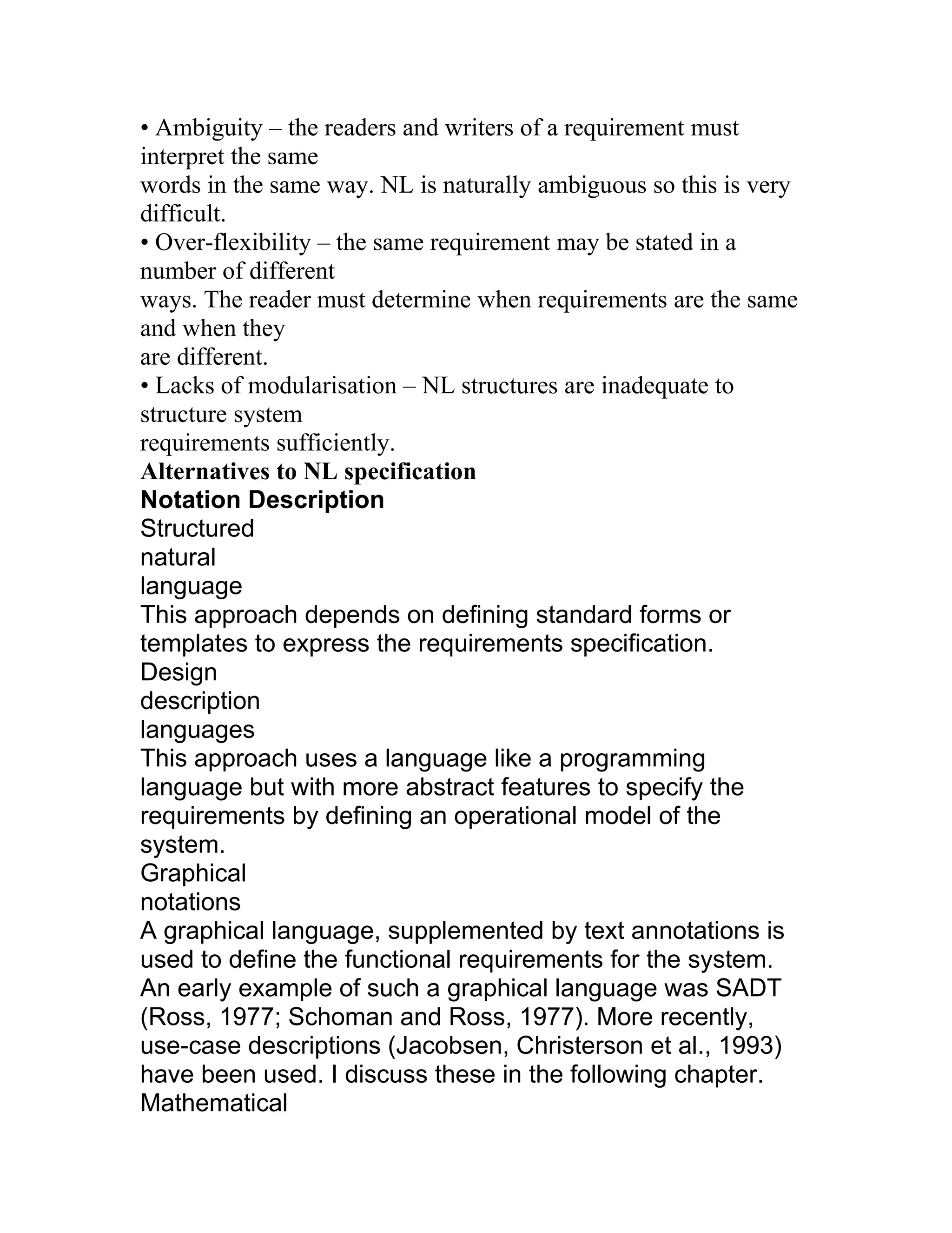
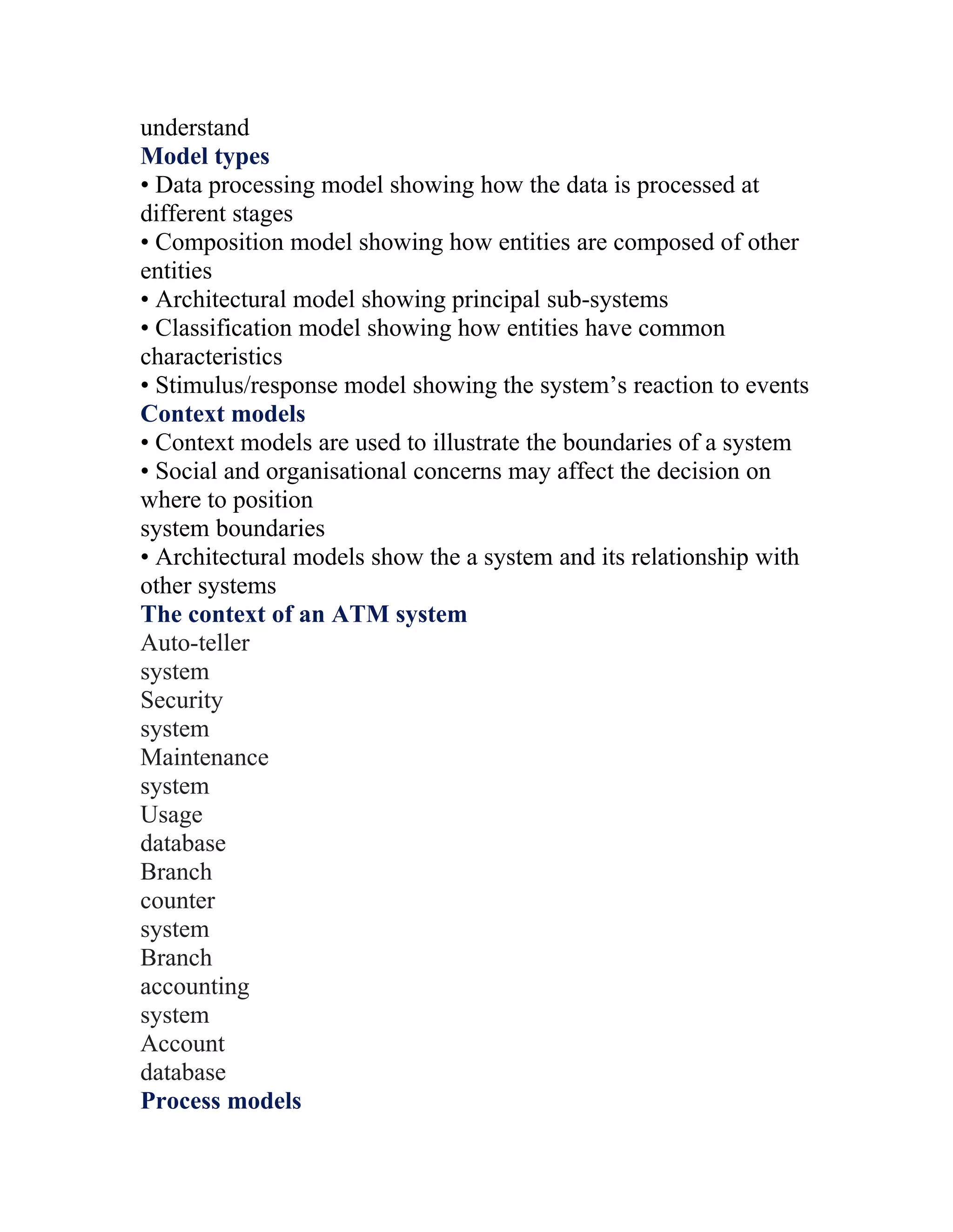
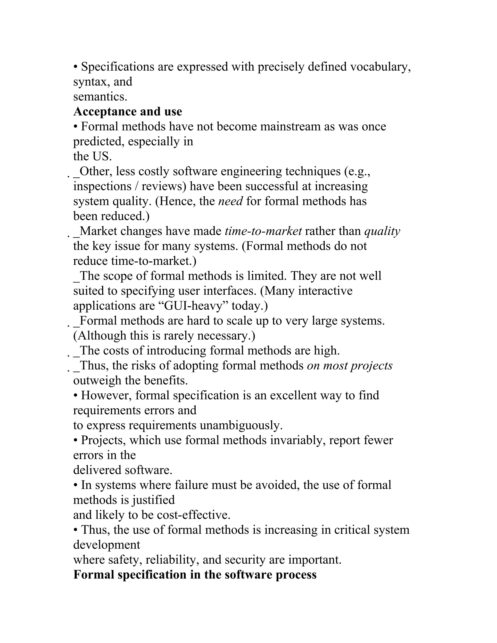
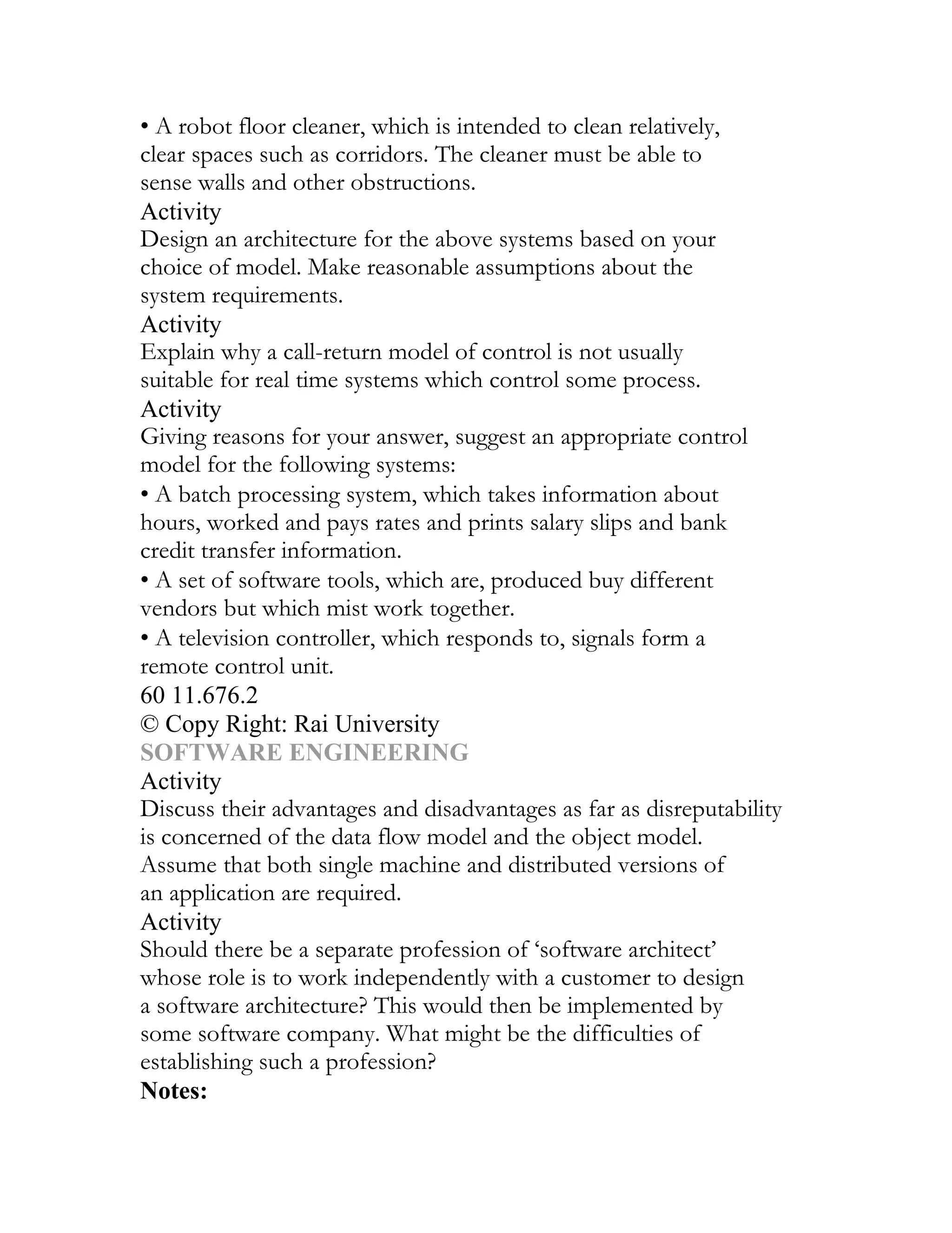
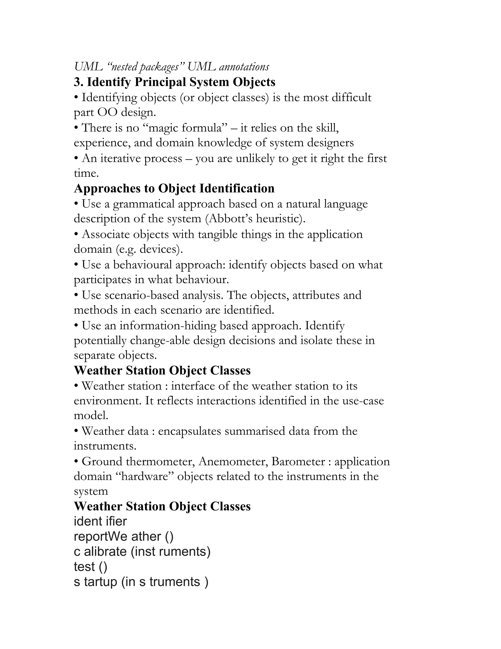
![requirements.
• Particularly useful in dealing with fragmentary, incomplete, or
conflicting
requirements.
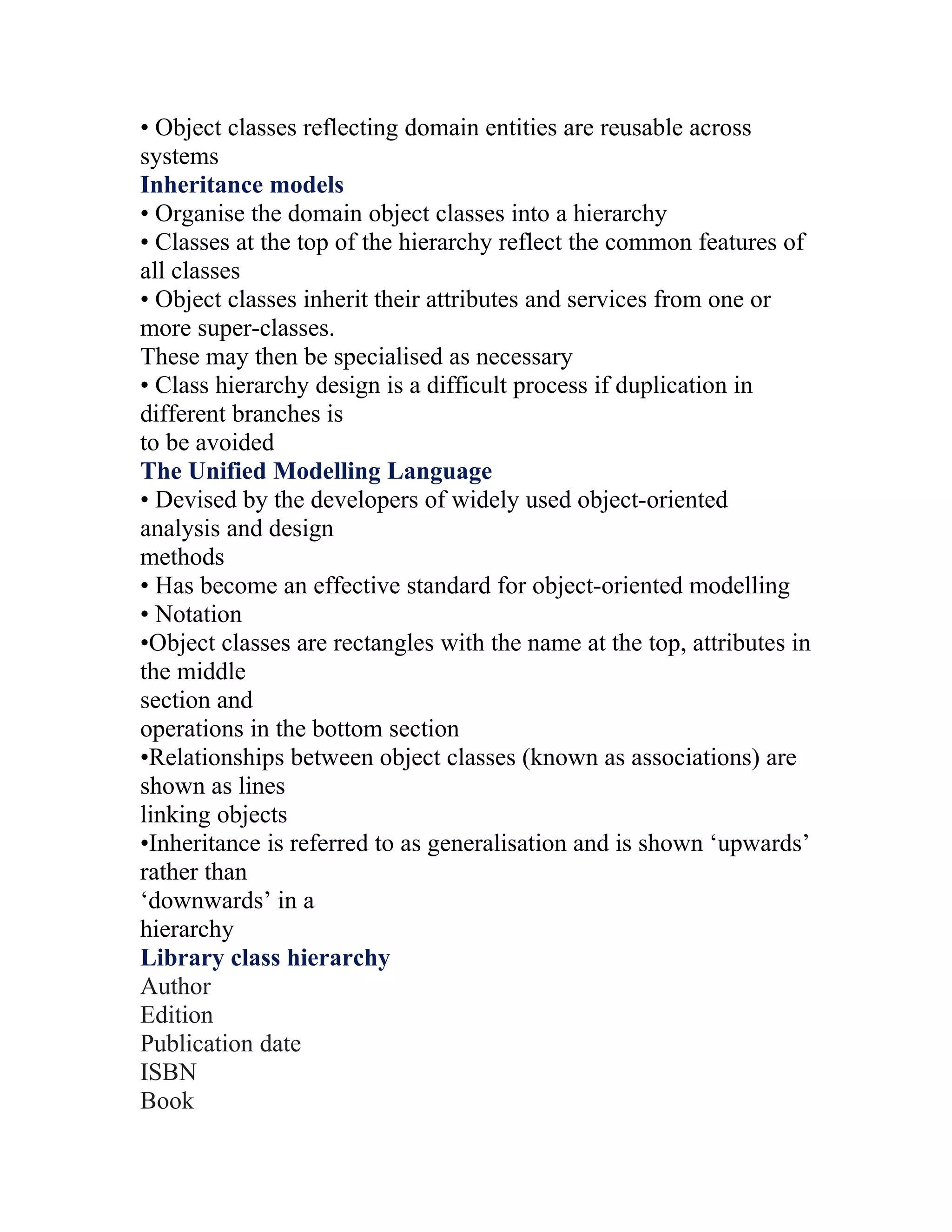
Scenario descriptions
• System state at the beginning of the scenario.
• Sequence of events for a specific case of some generic task the
system is required
to accomplish.
• Any relevant concurrent activities.
• System state at the completion of the scenario.
A simple scenario
• t0: The user enters values for input array A. The values are [1, 23,
-4, 7, 19]. The
value of output variable BIG remains ‘undefined’.
• t1: The user executes program MAX.
• t2: The value of variable BIG is 23 and the values of A are [1, 23,
-4, 7, 19].
Scenario-Based Requirements Engineering (SBRE)
• Marcel support environment allows rapid construction of an
operational
specification of the desired system and its environment.
• Based on a forward chaining rule-based language.
• An interpreter executes the specification to produce natural
language based
scenarios of system behavior.
SBRE rule template
SBRE scenario generation
Scenario representation in VORD
• VORD supports the graphical description of multi-threaded
“event scenarios” to
document system behaviour:
_Data provided and delivered
_Control information
_Exception processing](https://image.slidesharecdn.com/s1-120529084210-phpapp02/75/SOFTWARE-ENGINEERING-52-2048.jpg)

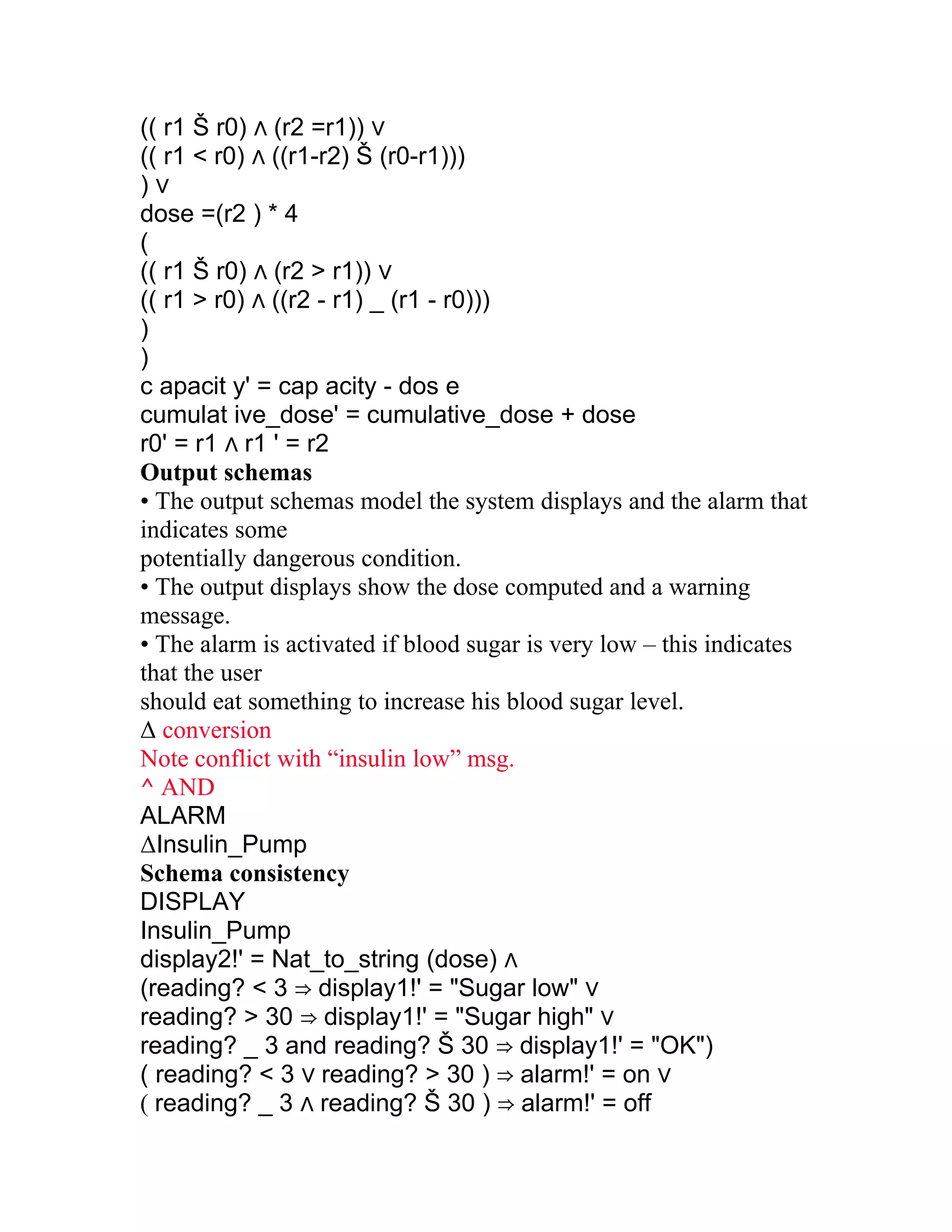
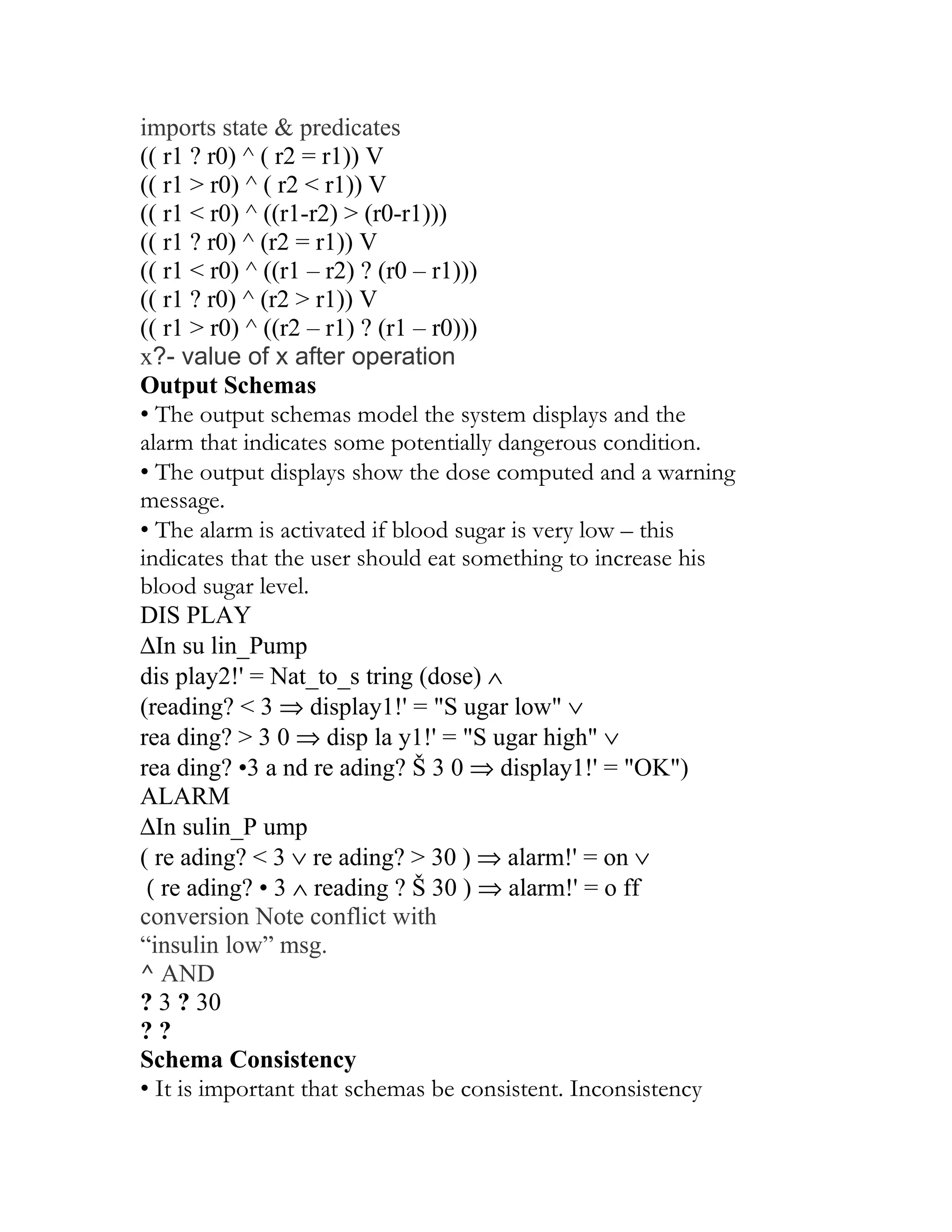
![• It is important that schemas be consistent. Inconsistency suggests
a problem with
system requirements.
• The INSULIN_PUMP schema and the DISPLAY are
inconsistent:
_display1! shows a warning message about the insulin reservoir
(INSULIN_PUMP)
_display1! Shows the state of the blood sugar (DISPLAY)
• This must be resolved before implementation of the system.
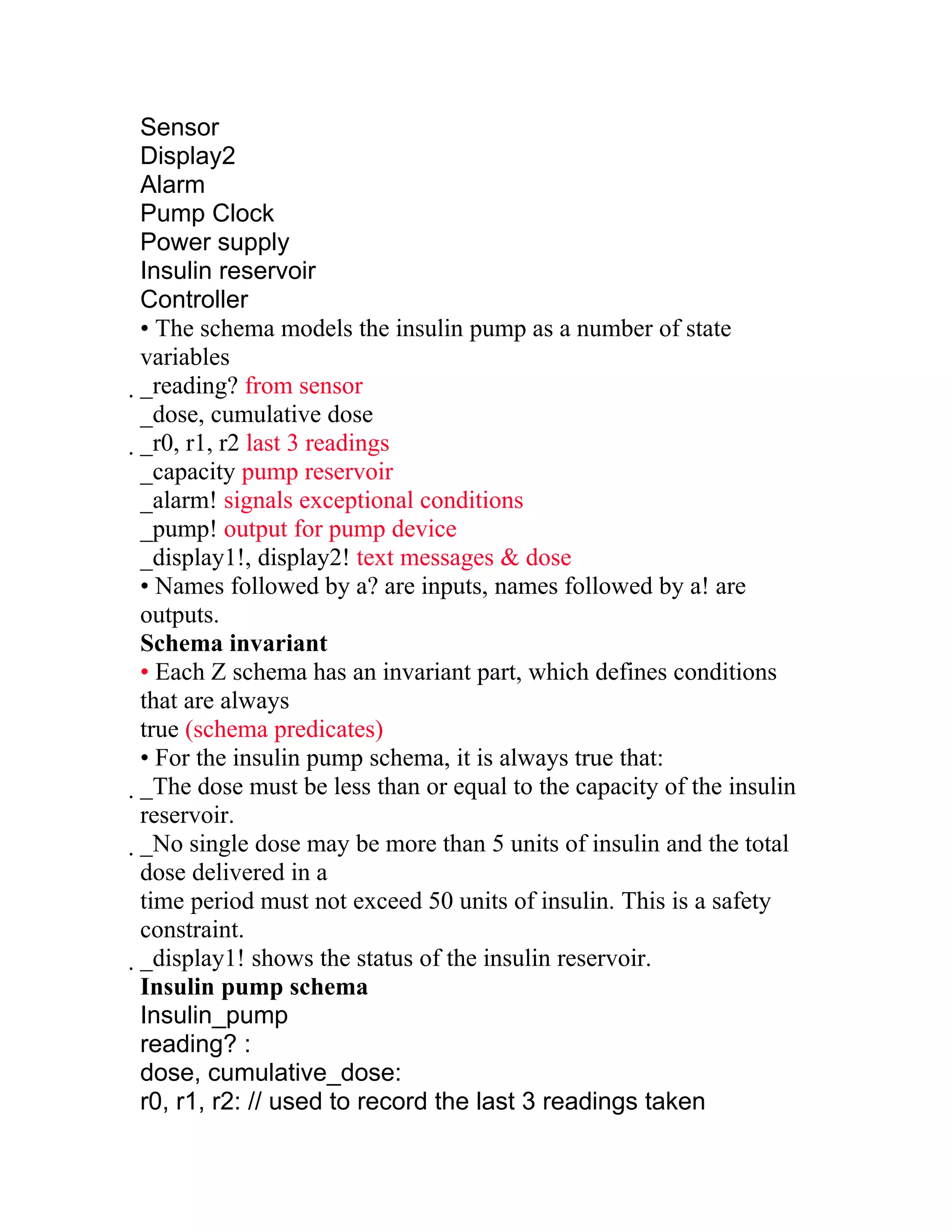
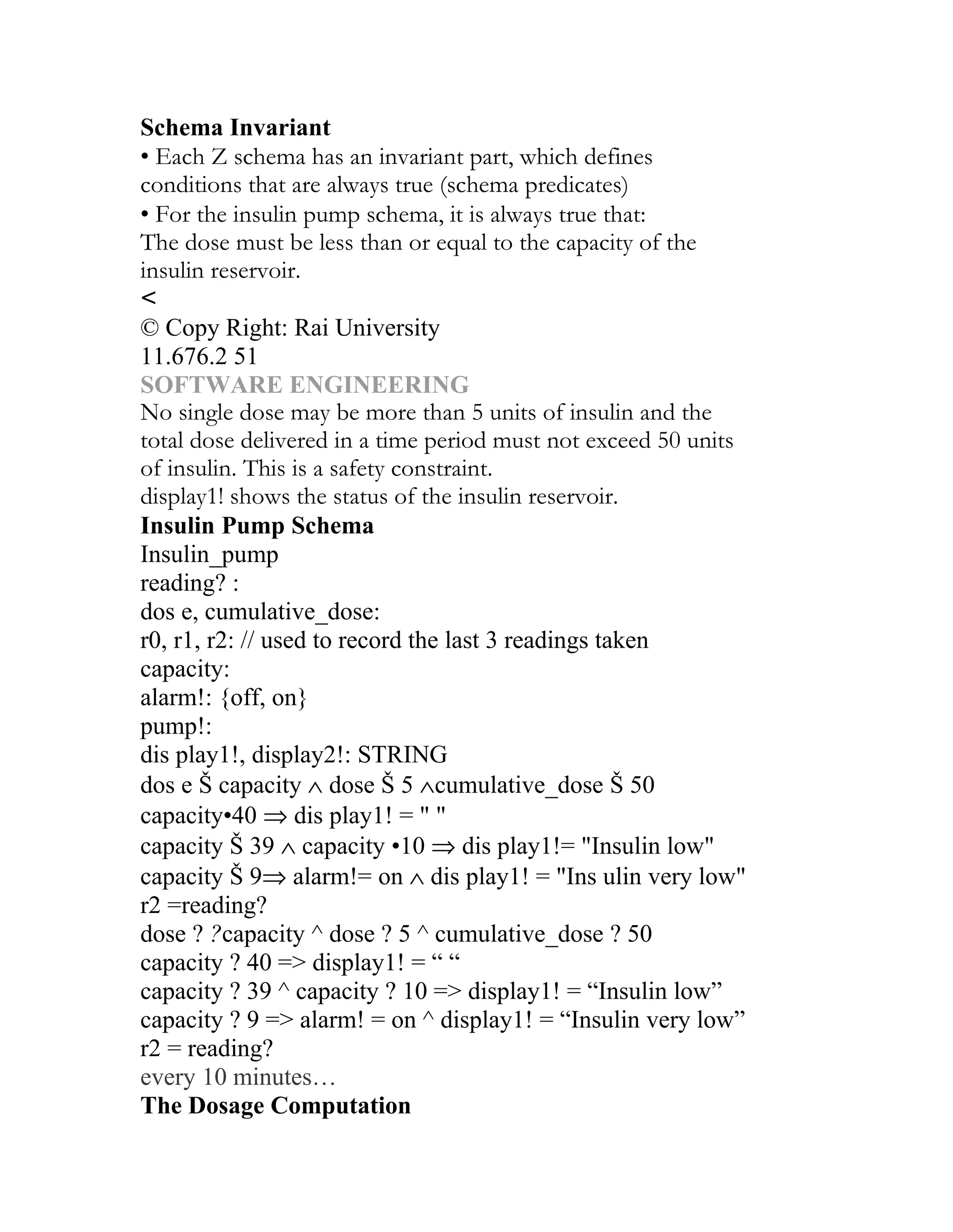
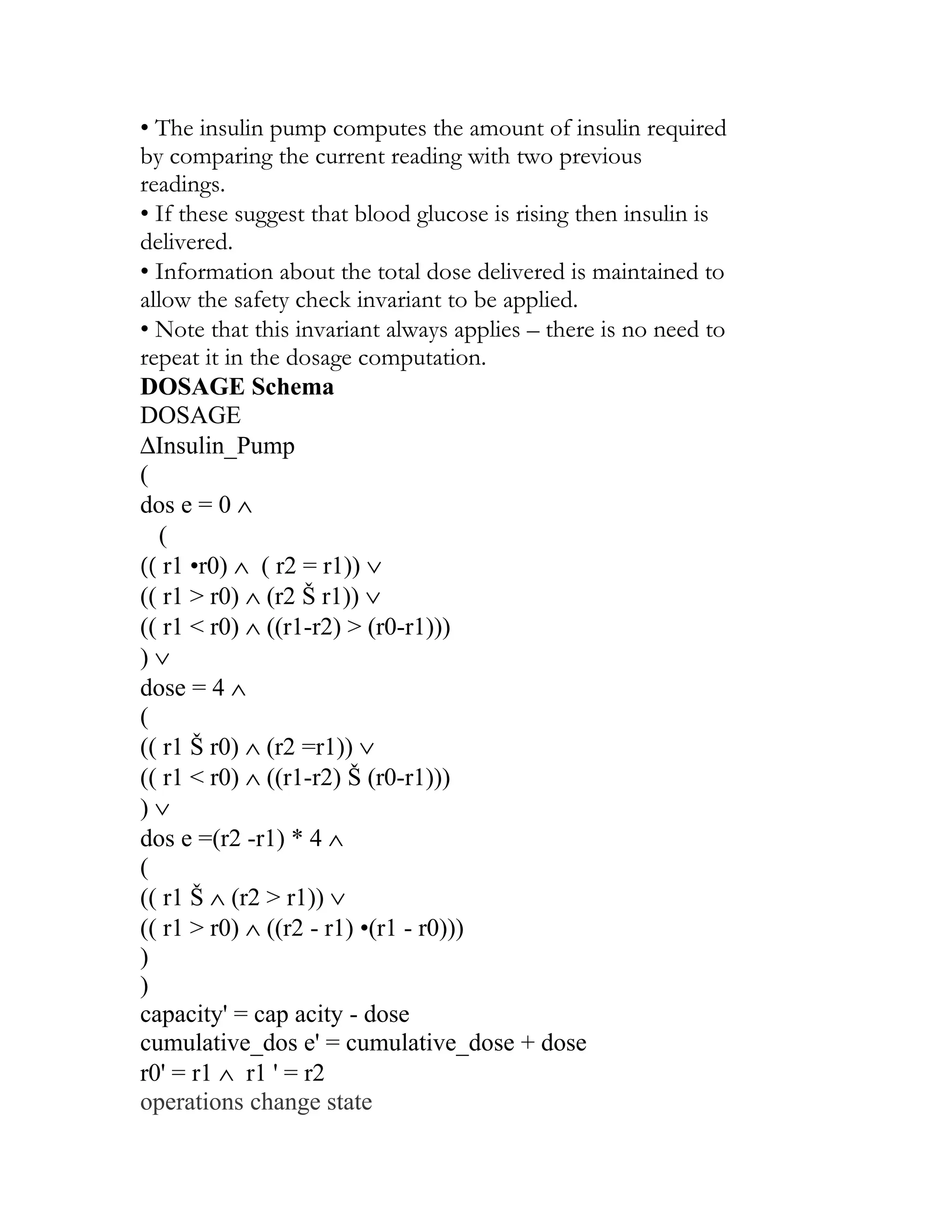
Specification via Pre- and Post-Conditions
• Predicates that (when considered together) reflect a program’s
intended functional
behavior are defined over its state variables.
• Pre-condition: expresses constraints on program variables before
program
execution. An implementer may assume these will hold BEFORE
program
execution.
• Post-condition: expresses conditions / relationships among
program variables
after execution. These capture any obligatory conditions AFTER
program
execution.
• Language: (first order) predicate calculus
_Predicates (X>4)
_Connectives (&, V, →, ó, NOT)
_Universal and existential quantifiers (for every, there exists…)
_Rules of inference (if A & (A → B) then B)
Example 1
• Sort a non-empty array LIST [1..N] into increasing order.
Pre-cond: N ≥ 1
Post-cond: For_Every i, 1 ≤ i ≤ N-1, LIST [i] ≤ LIST [i+1] &
PERM (LIST, LIST’)
Example 2](https://image.slidesharecdn.com/s1-120529084210-phpapp02/75/SOFTWARE-ENGINEERING-103-2048.jpg)
![• Search a non-empty, ordered array LIST [1..N] for the value
stored in KEY. If
present, set found to true and J to an index of LIST which
corresponds to KEY.
Otherwise, set FOUND to false.
Pre-cond: N ≥ 1 & [(“LIST is in increasing order”) V (“LIST is in
decreasing order”)]
(Exercise: express the “ordered” predicate above FORMALLY.)
Post-cond: [(FOUND & There Exists i, 1 ≤ i ≤ N | J=i & LIST
[J]=Key) V (NOT
FOUND & For_Every i, 1 ≤ i ≤ N, LIST [i] ≠KEY)] & UNCH
(LIST, KEY)
Key points
• Formal system specification complements informal specification
techniques.
• Formal specifications are precise and unambiguous. They remove
areas of doubt
in a specification.
• Formal specification forces an analysis of the system
requirements at an early
stage. Correcting errors at this stage is cheaper than modifying a
delivered system.
• Formal specification techniques are most applicable in the
development of critical
systems.
• Algebraic techniques are particularly suited to specifying
interfaces of objects and
abstract data types.
• In model-based specification, operations are defined in terms of
changes to system
state.
Activities
Activity 1:- Suggest why the architectural design of a system
should precede the
development of a formal specification.](https://image.slidesharecdn.com/s1-120529084210-phpapp02/75/SOFTWARE-ENGINEERING-104-2048.jpg)
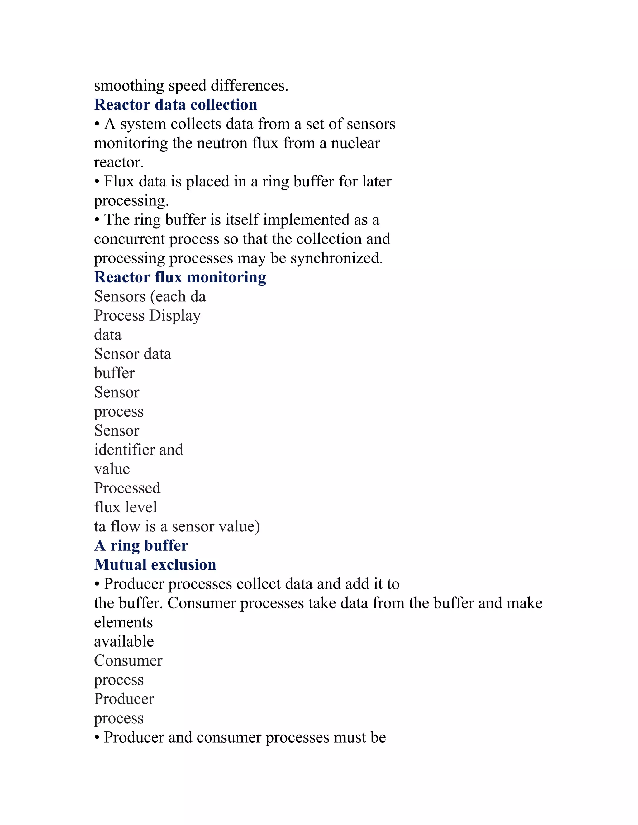
![mutually excluded from accessing the same
element.
• The buffer must stop producer processes
adding information to a full buffer and consumer processes trying
to take
information from an empty buffer.
Java implementation of a ring buffer 1
class CircularBuffer
{
int bufsize ;
SensorRecord [] store ;
int numberOfEntries = 0 ;
int front = 0, back = 0 ;
CircularBuffer (int n) {
bufsize = n ;
store = new SensorRecord [bufsize] ;
} // CircularBuffer
synchronized void put (SensorRecord rec ) throws
InterruptedException
{
if ( numberOfEntries == bufsize)
wait () ;
store [back] = new SensorRecord (rec.sensorId,
rec.sensorVal) ;
back = back + 1 ;
if (back == bufsize)
back = 0 ;
numberOfEntries = numberOfEntries + 1 ;
notify () ;
} // put
Java implementation of a ring buffer 2
synchronized SensorRecord get () throws
InterruptedException
{
SensorRecord result = new SensorRecord (-1, -1) ;](https://image.slidesharecdn.com/s1-120529084210-phpapp02/75/SOFTWARE-ENGINEERING-172-2048.jpg)
![if (numberOfEntries == 0)
wait () ;
result = store [front] ;
front = front + 1 ;
if (front == bufsize)
front = 0 ;
numberOfEntries = numberOfEntries - 1 ;
notify () ;
return result ;
} // get
} // CircularBuffer
Key points
• Real-time system correctness depends not just
on what the system does but also on how fast it
reacts
• A general RT system model involves associating processes with
sensors and
actuators
• Real-time systems architectures are usually designed as a number
of concurrent
processes
• Real-time executives are responsible for
process and resource management.
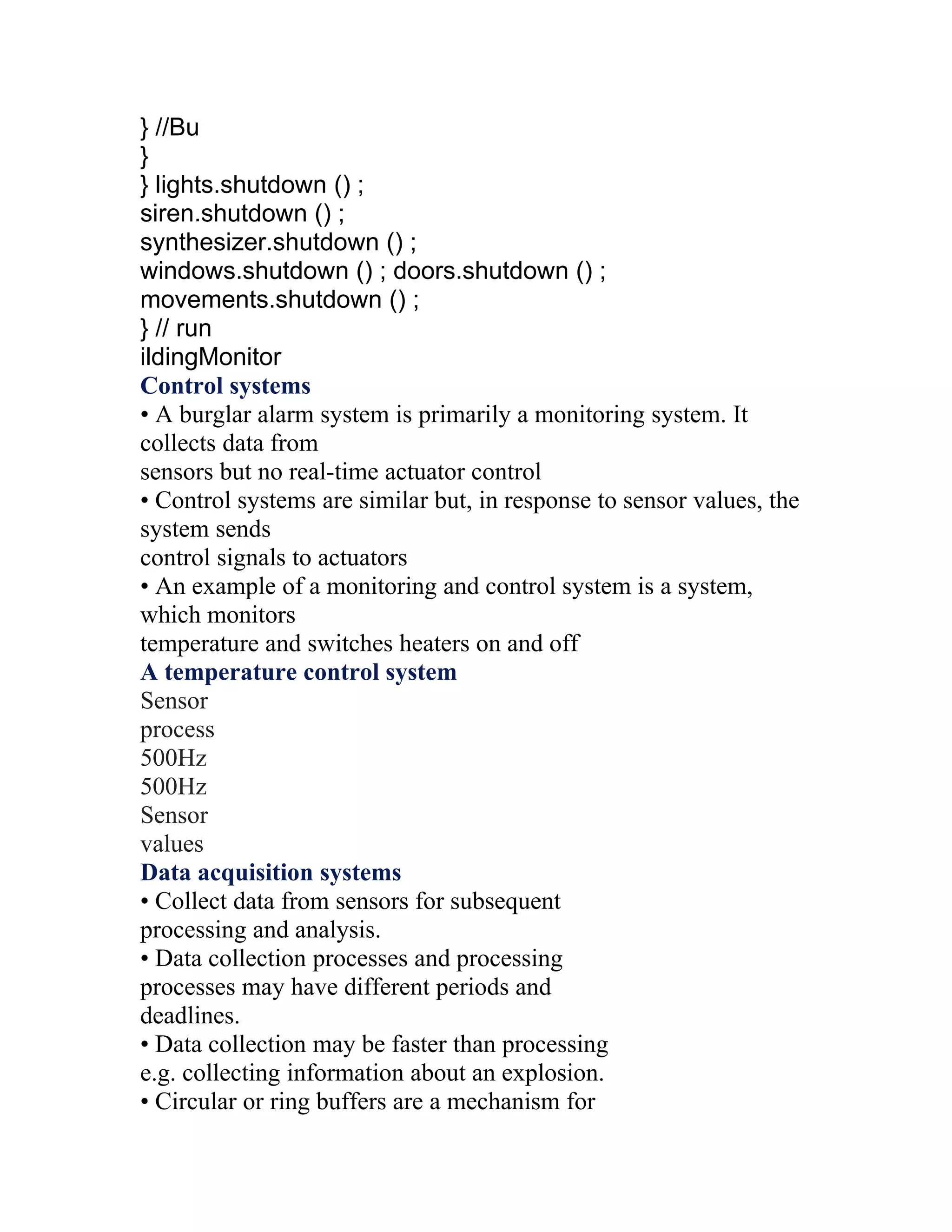
• Monitoring and control systems poll sensors and send control
signal to actuators
• Data acquisition systems are usually organised according to a
producer consumer
model
• Java has facilities for supporting concurrency but is not suitable
for the
development of time-critical systems
Activities
Activity 1:- Using examples, explain why real time systems
usually have to be
implemented using processes.](https://image.slidesharecdn.com/s1-120529084210-phpapp02/75/SOFTWARE-ENGINEERING-173-2048.jpg)

![suggests a problem with system requirements.
• The INSULIN_PUMP schema and the DISPLAY are
inconsistent:
display1! shows a warning message about the insulin reservoir
(INSULIN_PUMP)
display1! Shows the state of the blood sugar (DISPLAY)
• This must be resolved before implementation of the system.
Secification Via Pre-and Post-conditions
• Predicates that (when considered together) reflect a program’s
intended functional behavior are defined over its state
variables.
• Pre-condition: expresses constraints on program variables
before program execution. An implementer may assume
these will hold BEFORE program execution.
• Post-condition: expresses conditions / relationships among
program variables after execution. These capture any
obligatory conditions AFTER program execution.
• Language: (first order) predicate calculus
Predicates (X>4)
Connectives (&, V, →, ó, NOT)
Universal and existential quantifiers (for every, there exists…)
Rules of inference (if A & (A →B) then B)
Example 1
Sort a non-empty array LIST [1..N] into increasing order.
Pre-cond: N >1
Post-cond: For_Every i, 1 < i < N-1, LIST [i] < LIST [i+1] &
PERM (LIST, LIST’)
52 11.676.2
© Copy Right: Rai University
SOFTWARE ENGINEERING
Example 2
Search a non-empty, ordered array LIST [1..N] for the value
stored in KEY. If present, set found to true and J to an index
of LIST which corresponds to KEY. Otherwise, set FOUND to
false.](https://image.slidesharecdn.com/s1-120529084210-phpapp02/75/SOFTWARE-ENGINEERING-192-2048.jpg)
![Pre-cond: N > 1 & [(“LIST is in increasing order”) V (“LIST is
in decreasing order”)]
(Exercise: express the “ordered” predicate above FORMALLY.)
Post-cond: [(FOUND & There Exists i, 1 < i < N | J=i &
LIST [J]=Key) V (NOT FOUND & For_Every i, 1 < i < N,
LIST [i] ≠ KEY)] & UNCH (LIST, KEY)
Key Points
• Formal system specification complements informal
specification techniques.
• Formal specifications are precise and unambiguous. They
remove areas of doubt in a specification.
• Formal specification forces an analysis of the system
requirements at an early stage. Correcting errors at this stage
is cheaper than modifying a delivered system.
• Formal specification techniques are most applicable in the
development of critical systems.
• Algebraic techniques are particularly suited to specifying
interfaces of objects and abstract data types.
• In model-based specification, operations are defined in terms
of changes to system state.
Activity
Suggest why the architectural design of a system should precede
the development of a formal specification.
Activity
You have been given the task of selling formal specification
techniques to a software development organization. Outline
how you would go about explaining the advantages of formal
specifications to skeptical, practicing software engineers.
Activity
Explain why it is particularly important to define sub-system
interfaces in a precise way and why algebraic specification is
particularly appropriate for sub-system interface specification.
© Copy Right: Rai University
11.676.2 53
SOFTWARE ENGINEERING](https://image.slidesharecdn.com/s1-120529084210-phpapp02/75/SOFTWARE-ENGINEERING-193-2048.jpg)
![class CircularBuffer
{
int bufsize ;
SensorRecord [] store ;
int numberOfEntries = 0 ;
int front = 0, back = 0 ;
CircularBuffer (int n) {
bufsize = n ;
store = new SensorRecord [bufsize] ;
} // CircularBuffer
synchronized void put (SensorRecord rec ) throws
InterruptedException
{
if ( numberOfEntries == bufsize)
wait () ;
store [back] = new SensorRecord (rec.sensorId,
rec.sensorVal) ;
back = back + 1 ;
if (back == bufsize)
back = 0 ;
numberOfEntries = numberOfEntries + 1 ;
notify () ;
} // put
Java Implementation of a Ring Buffer 2
synchronized SensorRecord get () throws
InterruptedException
{
SensorRecord result = new SensorRecord (-1, -1) ;
if (numberOfEntries == 0)
wait () ;
result = store [front] ;
front = front + 1 ;
if (front == bufsize)
front = 0 ;
numberOfEntries = numberOfEntries - 1 ;](https://image.slidesharecdn.com/s1-120529084210-phpapp02/75/SOFTWARE-ENGINEERING-257-2048.jpg)

The document outlines the concepts of software and software engineering, emphasizing the differences between software engineering, computer science, and system engineering. It discusses the software process, including its activities like specification, development, validation, and evolution, as well as the financial aspects, methodologies, and ethical responsibilities of software engineers. Additionally, it stresses the importance of project management in delivering software on time and within budget, highlighting risk management and planning as essential components of successful software projects.
Definitions of software and software engineering, highlighting differences from computer science and system engineering.
Overview of software processes including specification, development, validation, and evolution, along with models like Waterfall and Agile.
Cost distribution in software engineering focused on development (60%) and testing (40%), outlining CASE tools and structured approaches.
Key challenges include managing legacy systems, meeting diverse requirements, and ensuring ethical practice in development.
Importance of ethical behavior in software engineering, covering ACM/IEEE Code of Ethics and professional responsibilities.
Detailed overview of the software process including specification, design, validation, and evolution.
Key activities including requirements elicitation, validation, and the design and implementation of software based on requirements.
Examines CASE tools' role in adhering to software processes and enhancing project management effectiveness.
Explains planning, scheduling, staffing, and common challenges in managing software projects.
Steps in effective project planning and scheduling, addressing common challenges and methods to optimize resource utilization.
Importance of risk management, processes involved in risk identification, analysis, and strategies for mitigation.
Focuses on the complex process of gathering, analyzing, and validating software requirements. Overview of re-engineering processes, including restructuring, reverse engineering, data recovery, and code translation. Explains the stages of software design, including system modeling, architectural design, and interface specifications.
Explains configuration management importance, activities, and managing system versions across development.