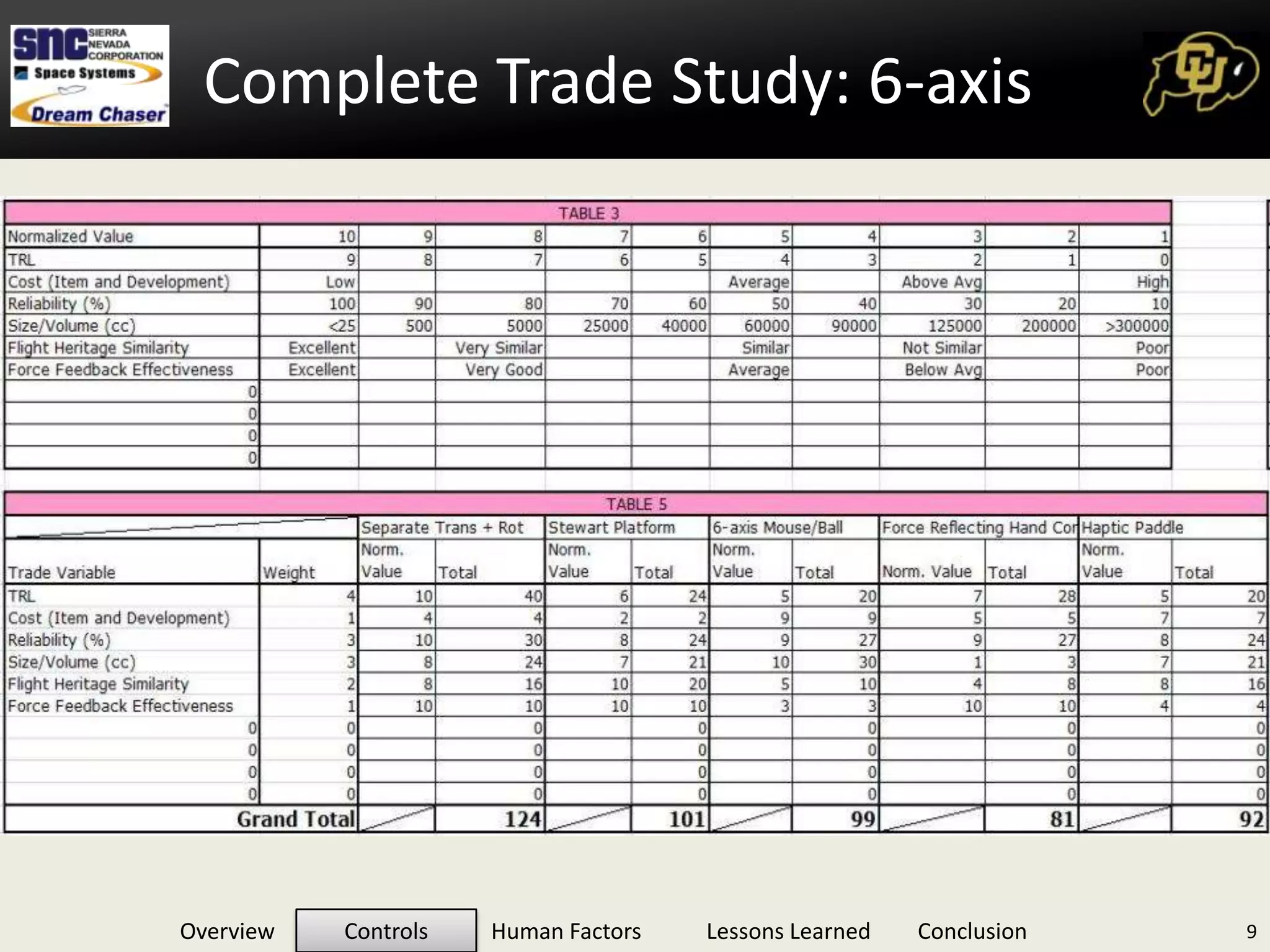
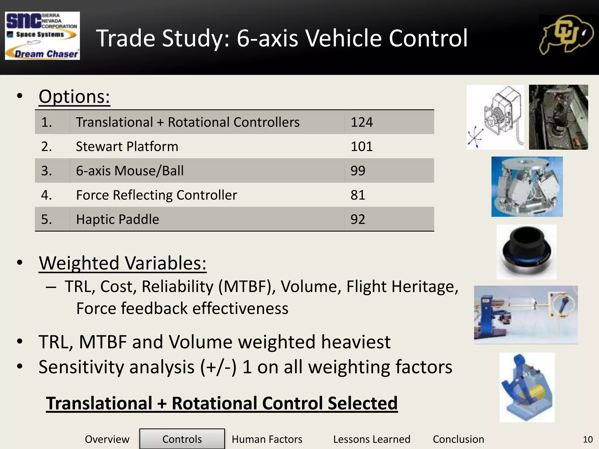
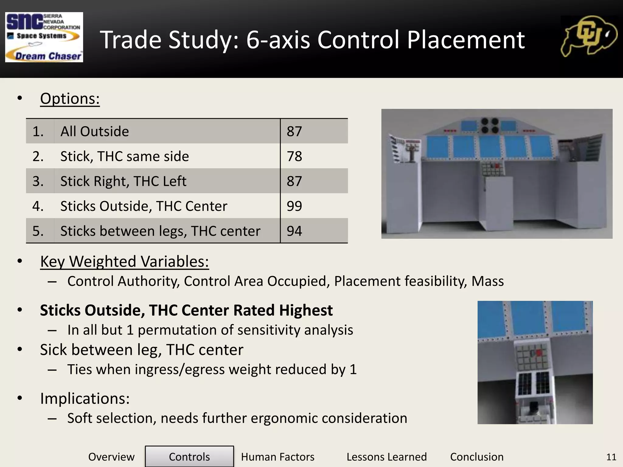
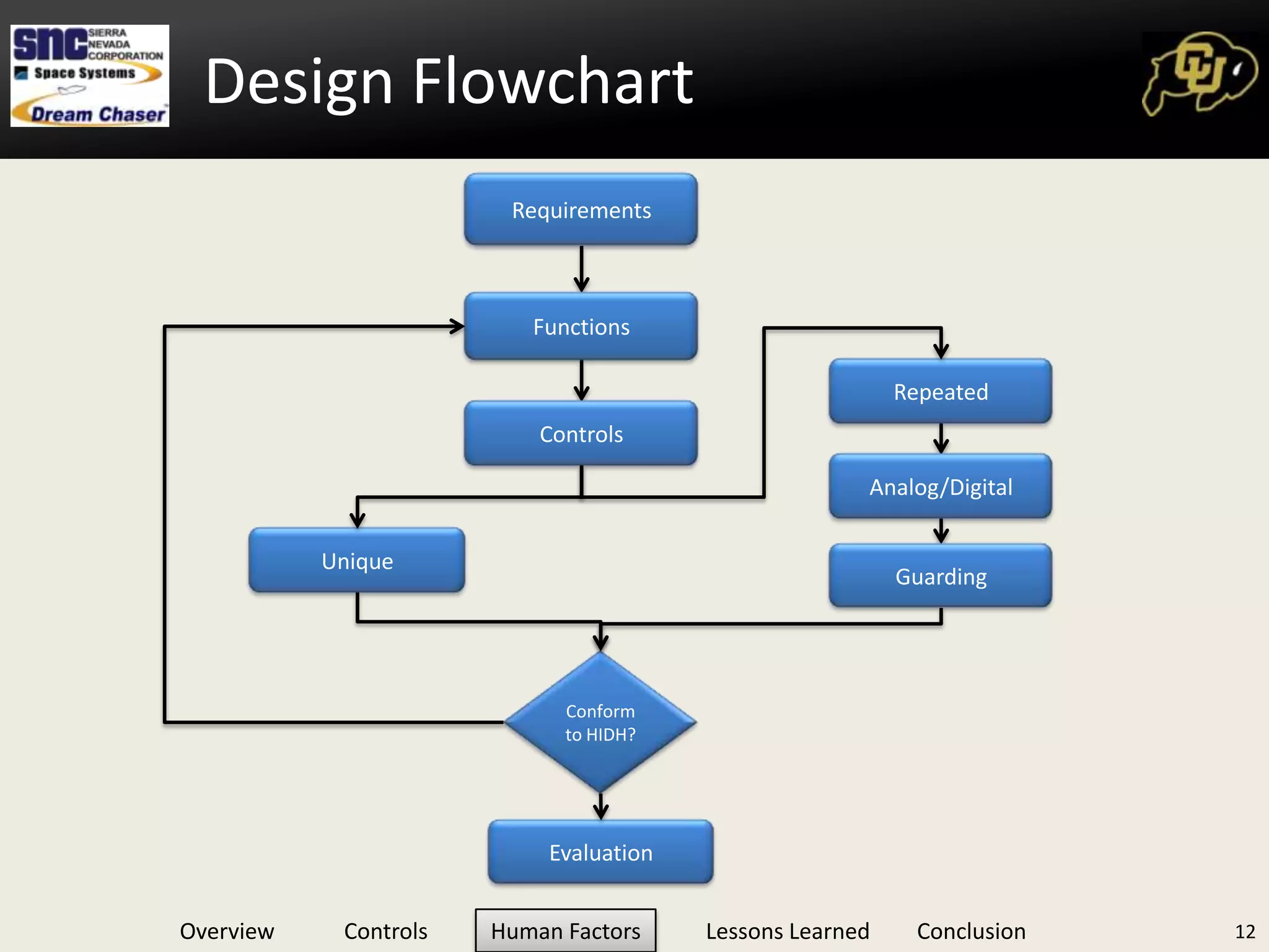
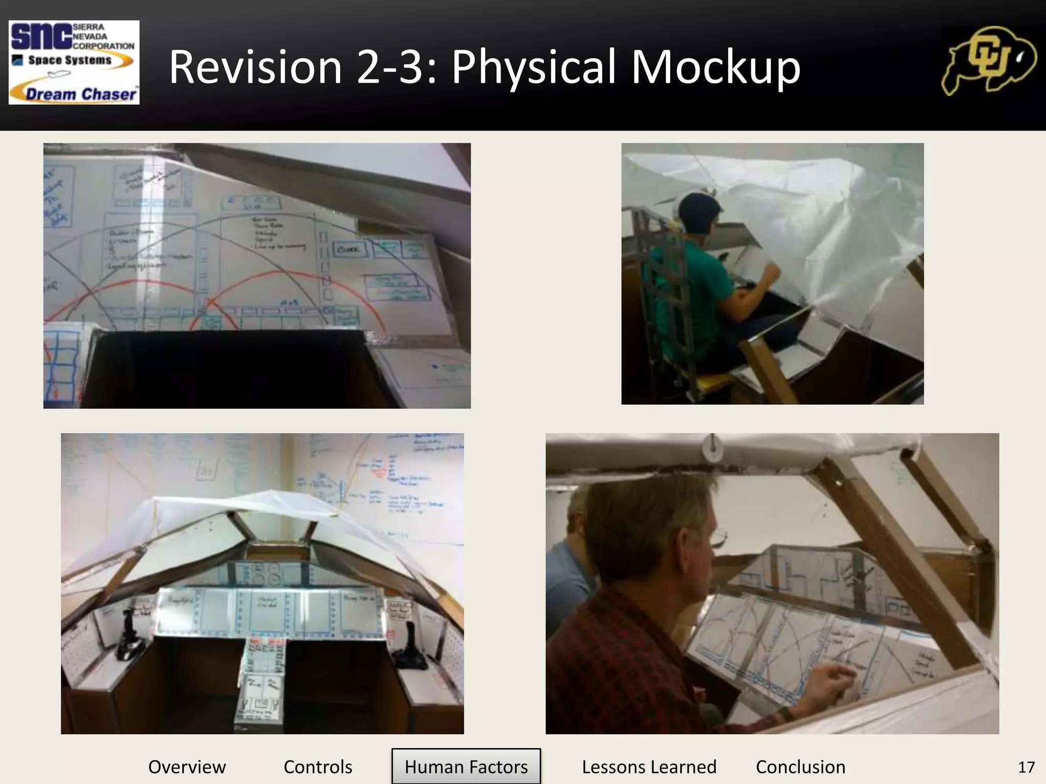
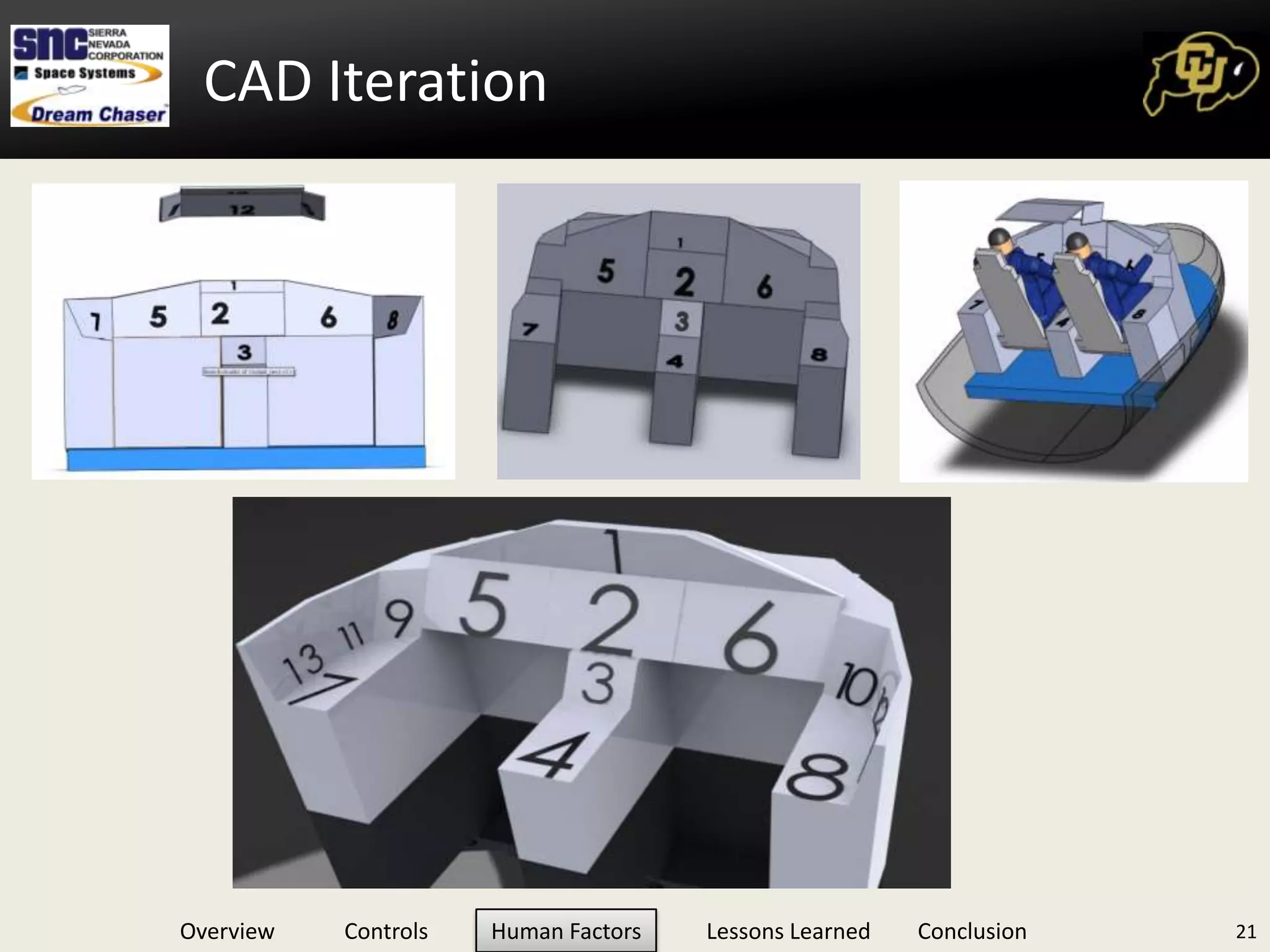
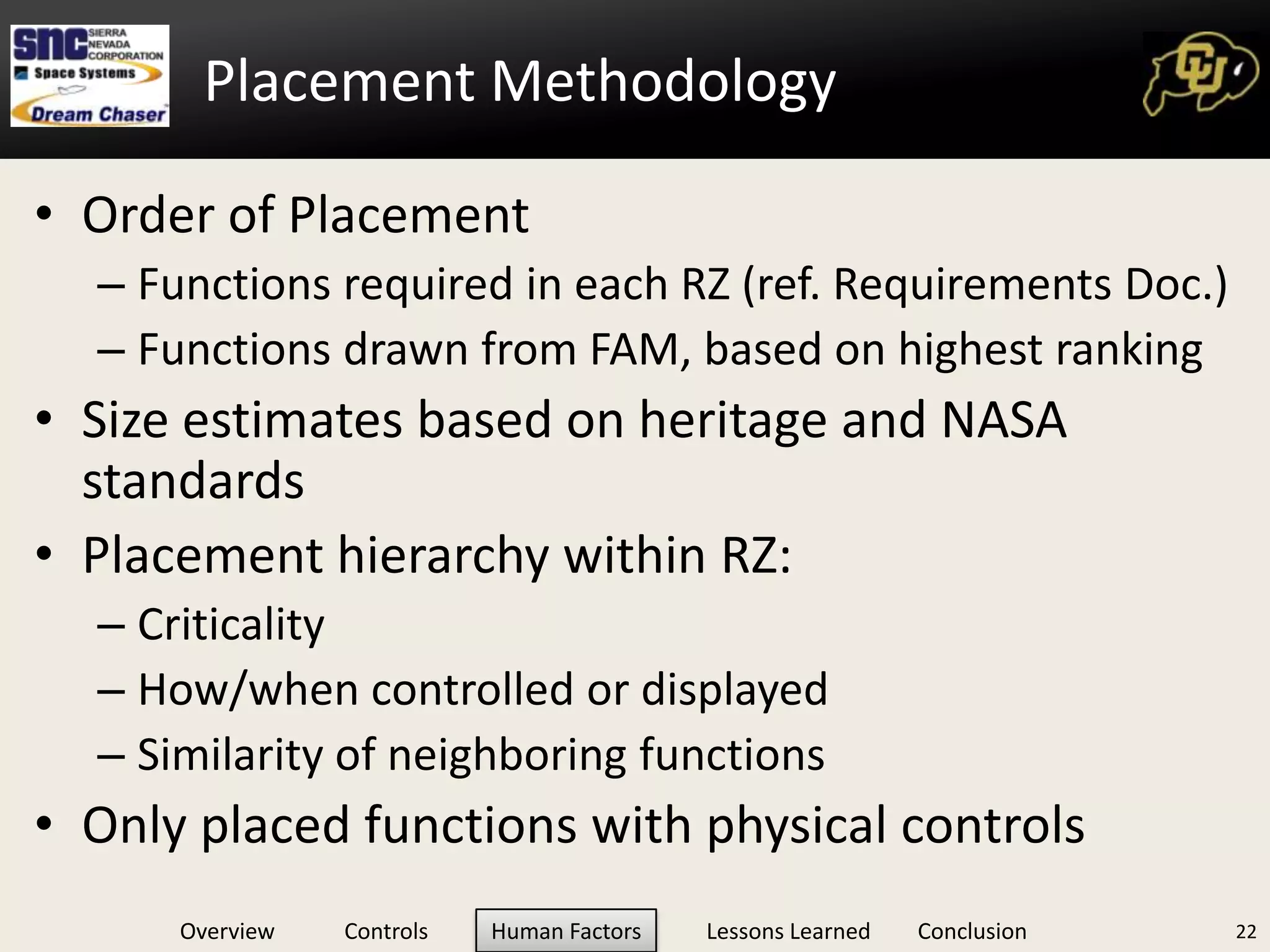
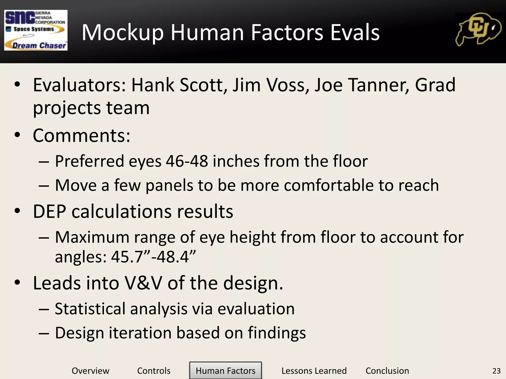
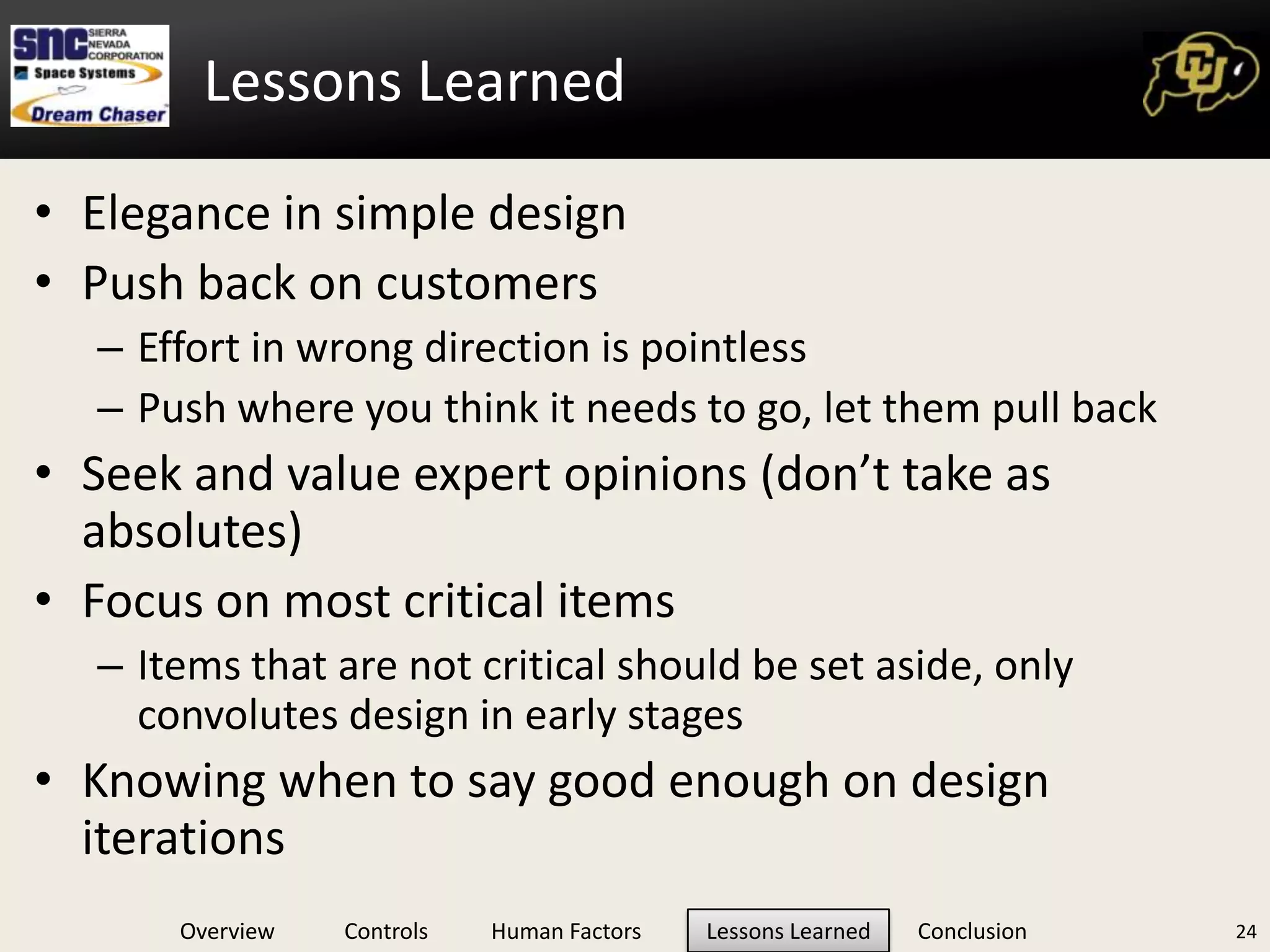
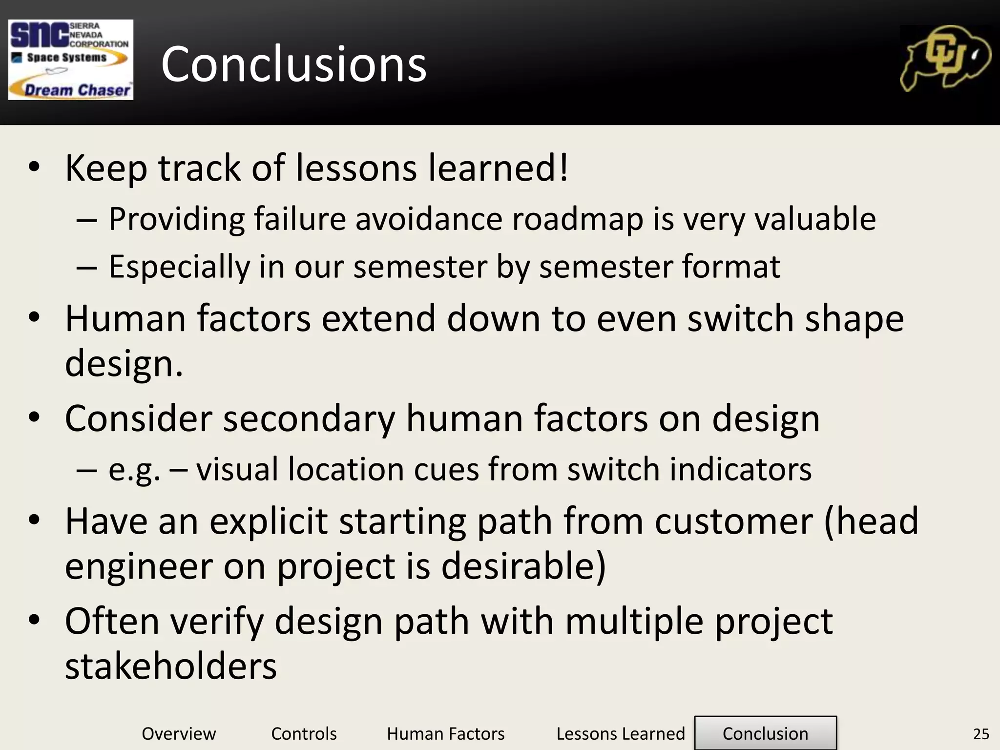
1. The Lessons Learned from Designing a Spacecraft Cockpit April 6th, 2011 :: Bioastronautics Seminar
2. Mission: “Safely transport crew/ cargo to/from the International Space Station and return them safely to Earth” (DRM, p.17) Funded by the CCDev Program Uses the OML of the HL-20 2 Dream Chaser Vehicle Overview
3. Provided Information from Customer Mission phases ROUGH Requirements Mission objective Inner Mold Lining in CAD General deliverables (Baseline Architecture, etc.) A few key milestones (TIM, Mid, Final Pres) Is this enough? 3 Team Starting Point
4. You are not a pilot You have design experience but only a Passenger-esque familiarity with cockpit layouts You have little spacecraft ops knowledge You have been tasked to design a spacecraft cockpit Where do you start? 4 Starting from Scratch
5. Differs from PhD Mass information collection Basics through advanced details Explore complete design space Think outside the box, do not exclude the fantastic! (Until you have to) Synthesis of best practices, customer provided guidelines, and NASA document requirements = Leading Considerations Drives philosophy of technology selection and design complexity Distil the information down to directly relevant 5 Literature Research, et al.
21. Trade Study: 6-axis Vehicle Control Options: Weighted Variables: TRL, Cost, Reliability (MTBF), Volume, Flight Heritage, Force feedback effectiveness TRL, MTBF and Volume weighted heaviest Sensitivity analysis (+/-) 1 on all weighting factors Translational + Rotational Control Selected 10
22. Trade Study: 6-axis Control Placement Options: Key Weighted Variables: Control Authority, Control Area Occupied, Placement feasibility, Mass Sticks Outside, THC Center Rated Highest In all but 1 permutation of sensitivity analysis Sick between leg, THC center Ties when ingress/egress weight reduced by 1 Implications: Soft selection, needs further ergonomic consideration 11
23. Design Flowchart 12 Requirements Functions Repeated Controls Analog/Digital Unique Guarding Conform to HIDH? Evaluation
24. Human Machine Integration Flowchart Human Integration Design Considerations: Operation and manipulation in expected G profiles, any suited conditions, deconditioned crew, and conform to ‘blind’ operation. Ease of identification via consistent labeling, color coding, shape, operation, tactility. Controls will be selected with consideration to sequence, grouping, efficiency, and so no one limb is over-burdened. Controls will be identified by level of criticality. This will drive chosen redundancy, robustness and will restrict location. Protected from inadvertent actuation or movement. Any control protection method should not preclude operation within the time required. Etc.. 13
25. Switches Overview All Switches: Meet NASA 50005, STD 3000 and HIDH standards Assumed to have barrier guarding or caging Map to only one function Switch Areas: Analog Types: Control Knob, Crank, Slide Switches, Lever Switch Digital Types: Rocker Switch, Toggle Switch, Push Buttons, Legend Buttons Custom: 6-axis Stick, Keyboards, Breakers 14
26. Switch Area Calculation Tool Σ(Number of switches * (Average switch area + Spacing area)) & +50% margin First Cut: 68 Individual Controls, 1.84 sq ft. Revision 1: 55 Hardware Controls, 1.5 sq ft. 22.6% Reduction in Area Tool Range:445 – 1108 cm2 ( 0.47 – 1.18 sq ft.) Compare to Mock-Up: 61 controls x 16 cm2/control = 976 cm2 15
27. DERP: The Human In The Loop Design Eye Reference Point (DERP) We need a build-to reference point. Build around human or adjust human to other constraints? 16
30. Placement Methodology Began with mapping reach zones onto mockup Used team member with approximately 50% American male arm span (68”) Team member position adjusted to required eye height (washer) Traced Reach Zone (RZ) semi-circles with marker tip and fingertip Estimated RZ 1 Person attached to seat by straps to simulate high g-loading Estimated RZ 2 Person told to keep back against seat, but able to move shoulders Semi-circles indicate what zones in the mockup available for placement 19
33. Placement Methodology Order of Placement Functions required in each RZ (ref. Requirements Doc.) Functions drawn from FAM, based on highest ranking Size estimates based on heritage and NASA standards Placement hierarchy within RZ: Criticality How/when controlled or displayed Similarity of neighboring functions Only placed functions with physical controls 22
34. Mockup Human Factors Evals Evaluators: Hank Scott, Jim Voss, Joe Tanner, Grad projects team Comments: Preferred eyes 46-48 inches from the floor Move a few panels to be more comfortable to reach DEP calculations results Maximum range of eye height from floor to account for angles: 45.7”-48.4” Leads into V&V of the design. Statistical analysis via evaluation Design iteration based on findings 23
35. Elegance in simple design Push back on customers Effort in wrong direction is pointless Push where you think it needs to go, let them pull back Seek and value expert opinions (don’t take as absolutes) Focus on most critical items Items that are not critical should be set aside, only convolutes design in early stages Knowing when to say good enough on design iterations 24 Lessons Learned
36. Conclusions Keep track of lessons learned! Providing failure avoidance roadmap is very valuable Especially in our semester by semester format Human factors extend down to even switch shape design. Consider secondary human factors on design e.g. – visual location cues from switch indicators Have an explicit starting path from customer (head engineer on project is desirable) Often verify design path with multiple project stakeholders 25
38. References “Characterizing Scan Patterns in a Spacecraft Cockpit Simulator: Expert vs. Novice Performance.” Huemer, Valerie A., Hayashi, Miwa. Proceedings of the Human Factors and Ergonomics Society, 49th Annual Meeting. 2005. “Cockpit and mission system modernization”, Don. Anttila, Kyle DeLong, Mike Skaggs and Scott White. Published in Aircraft Engineering and Aerospace Technology, Vol. 72, Iss.2 pg 143-155. 2003. “Cognitive Engineering: Issues in User-Centered System Design”, Emilie M. Roth, Emily S. Patterson and Randall J. Mumaw. Published in Encyclopedia of Software Engineering, 2nd Edition. New York: Wiley Interscience, John Wiley & Sons. “Crew and Display Concepts Evaluation for Synthetic/Enhanced Vision Systems”, Randall E. Bailey, Lynda J. Kramer and Lawrence J. Prinzel III. NASA Langley Research Center, VA. Published in SPIE Proceedings Vol. 6226 – Enhanced and Synthetic Vision 2006, May 20 2006. FAA Human Factors Design Standards, Federal Aviation Administration. http://hf.tc.faa.gov/hfds/download_received.htm, 2003 edition with October 2009 updates. Chapters 2, 5 and 6. Federal Standard, FED-STD-595, “Colors Used in Government Procurement.” Revision C, January 2008. Handbook for Human Engineering Design Guidelines, Department of Defense. Mil-Hdbk-759C. July 31, 1995. “Heads Up Display”. http://www.skybrary.aero/index.php/Head_Up_Display. Last modified July 20, 2010. “High Altitude Reconnaissance Aircraft Design.” California State Polytechnic University, Pomona. July 1990. “Human Factors Design Guidelines for Multifunction Displays.” S. Mejdal, Michael E. McCauley and Dennis B. Beringer. Office of Aerospace Medicine, Washington D.C. and the USDT and the FAA. DOT/FAA/AM-01/17. October 2001. “Human Factors in the Design of Spacecraft.” Wichman, Harvey. Aerospace Psychology Laboratory. New York, NY. 1992. “Human Performance in Six Degree of Freedom Input Control.” Zhai, Sumhim. University of Toronto. 1995. “Integrated Large Cockpit Display System”, Teshome G. Diriba. University of Maryland Eastern Shore Aviation Sciences Program. May 12, 2009. JSC-28607, CRV Displays and Controls Requirements, Rev A. National Aeronautics and Space Administration, Lyndon B. Johnson Space Center, Houston, TX 77058, June 2002. Man-System Integration Standard, NASA STD-3000, Volume I, Revision B, July 1995. Military Standard, MIL-STD-1472. “Human engineering design criteria for military systems, equipment and facilities. 1999 “Multi-Model Cockpit Interface for Improved Airport Surface Operations.” Arthur, Jarvis J., Randall E. Bailey, Lawerence J. Prinzel, III, Lynda J. Kramer, and Steven P. Williams. The United States of America, assignee. Patent US 7,737,867 B2. 15 June 2010. “NASA Comparison of Pilot Effective Time Delay for Cockpit Controllers Used on Space Shuttle and Conventional Aircraft”, 1986 “NASA Orion Crew Vehicle will use voice controls in Boeing 787-style Honeywell smart cockpit.” Flightglobal, 2006. Product Focus: Cockpit Displays: LCDs vs. CRTs, Charlotee Adams. http://www.aviationtoday.com/av/categories/commercial/665.html. January 1, 2003. “Steam Gauges or Glass, What’s Your Choice?”, Dan Farnsworth. http://www.danfarnsworth.com/?p=158. August 4 2010. “Synthetic Vision System”. http://en.wikipedia.org/wiki/Synthetic_vision_system. Last modified August 19, 2010. Virtual Environment Display System, S.S. Fisher, M. McGreevy, J. Humphries and W. Robinett. NASA Ames Research Center. Published in Symposium on Interactive 3D Graphics: Proceedings of the 1986 workshop on Interactive 3D graphics. Pg. 77-87, 1987. 27
39. Issues: Limited ergonomic reach Suited operation restrictions TRL of selected hardware 28 Risks and Issues
Editor's Notes
Point….need to push back on customer to get a clear picture in the beginning.
Put these into the backup slides
Describe locations on picture
Map to one function - multi-function controls are considered separately.