Download to read offline
![International Research Journal of Engineering and Technology (IRJET) e-ISSN: 2395-0056
Volume: 04 Issue: 10 | Oct -2017 www.irjet.net p-ISSN: 2395-0072
© 2017, IRJET | Impact Factor value: 6.171 | ISO 9001:2008 Certified Journal | Page 1108
6. CONCLUSION
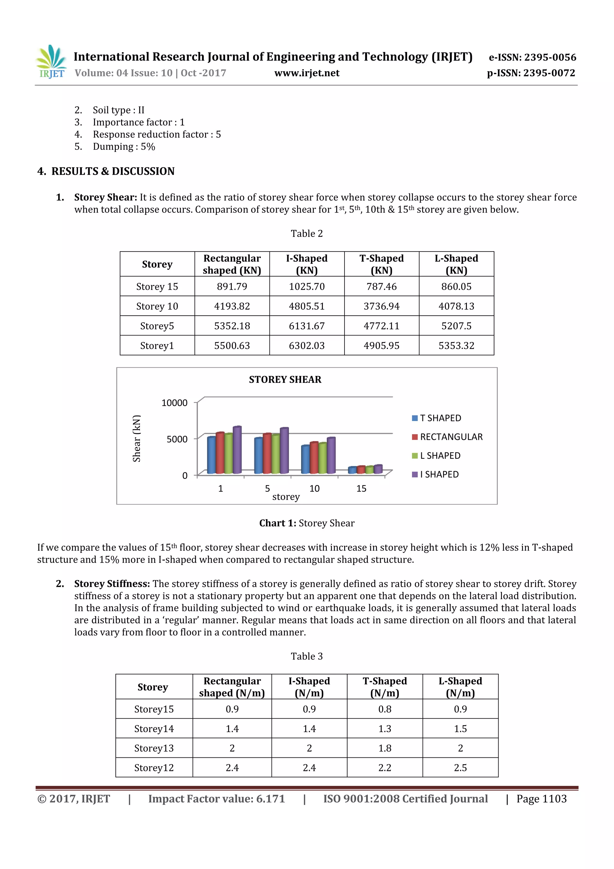
1. Storey shear inversely varies with respect to number of storeys.
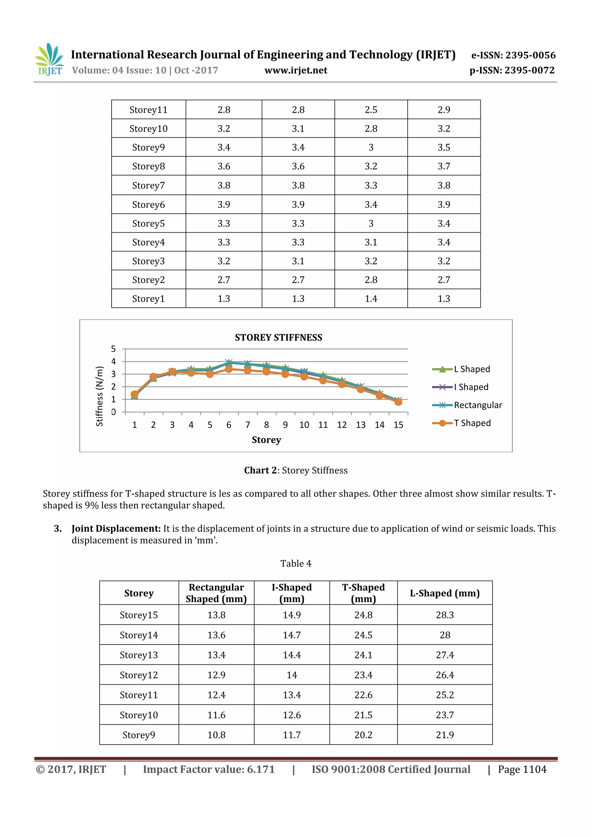
2. Storey stiffness increases with increase in storey height. But this case is satisfied only till 6th storey level. The
value of shear stiffness is maximum for all the shape. But after 6th storey, the stiffness goes on decreasing.
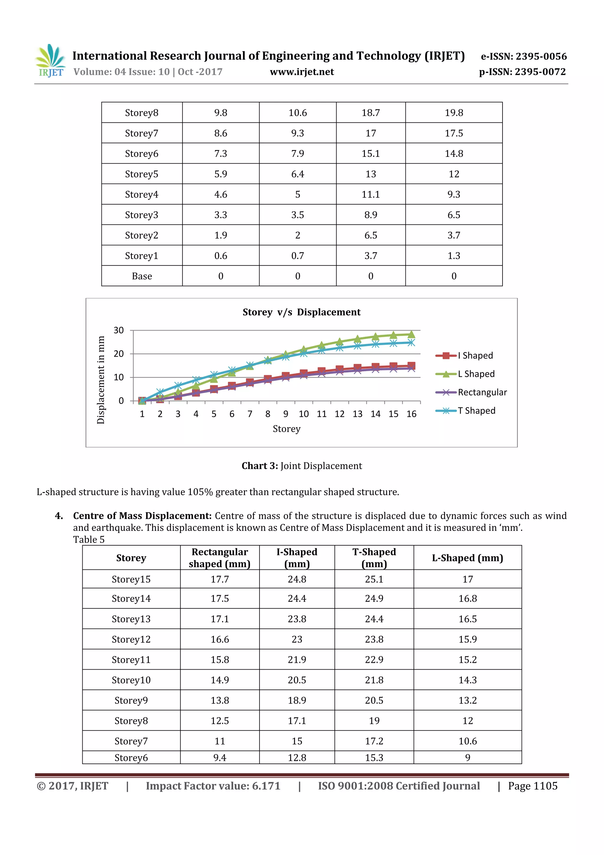
3. Joint displacement is directly proportional to the storey levels or no of storey. The values are maximum for L-
shaped structure suggesting maximum deformation in that particular shape. It is lowest in rectangular shaped
structure due to similarity of the structure.
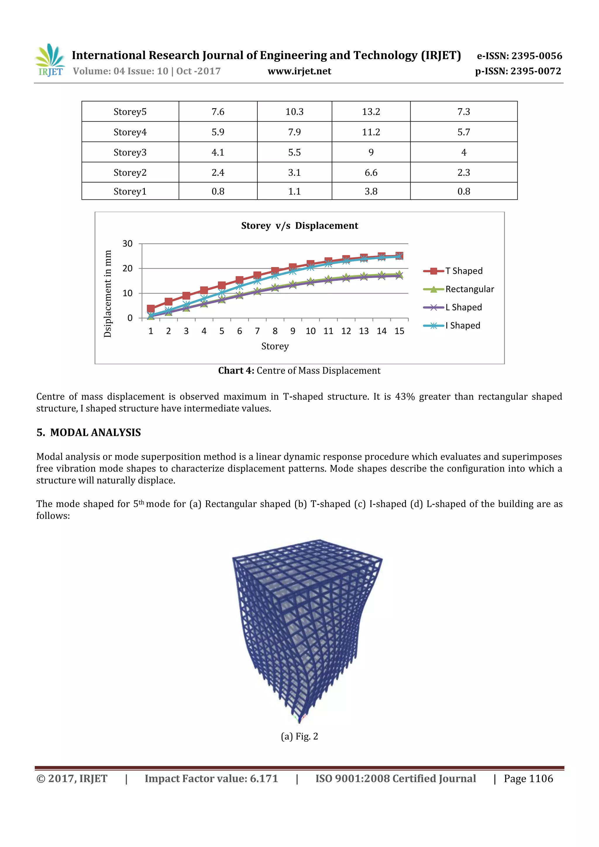
4. Centre of mass displacement is directly proportional to number of storeys. It is observed that maximum value of
Centre of mass displacement is in T-shaped structure followed by I-shaped structure. L-shaped structure has the
lowest value amongst the 4 shapes.
5. It is observed that asymmetrical plans undergo more deformation than symmetrical plans and therefore while
constructing a new structure in high seismic zone, it is most likely to construct a structure which is symmetric in
shape so as to provide better stability.
REFERENCES
1. ETABS – 02 Introductory Tutorial Steel: Watch & Learn from YouTube published on 23rd April 2013.
2. Illustrated Design of Reinforced Concrete Buildings by Dr. V.L. Shah and S.R. Karve.
3. IS 1893-1 (2002): Criteria for Earthquake Resistant Design of Structure, Part 1: General Provisions and Buildings
[CED 39: Earthquake Engineering].
4. IS 456 (2000): Plain and Reinforced Concrete - Code of Practice [CED 2: Cement and Concrete]
5. Milind V. Mohod, “Effect of shaped and plan configuration on seismic response of structure,”International Journal
of Scientific & Technology Research, Volume 4, Issue on 09 September 2015.
6. Mohammed Rizwan Sultan, “Dynamic analysis of multi-storey building for different shapes,” International Journal
of Innovative Research in Advanced Engineering (IJIRAE), Volume 2, Issue on August 2015.
7. Sameer Pardeshi, “Study of seismic analysis and design of multi storey symmetrical and asymmetrical building,”
International Research Journal of Engineering and Technology (IRJET), Volume 3, Issue on 01 January 2016.](https://image.slidesharecdn.com/irjet-v4i10201-171129093552/75/Seismic-Analysis-of-Multistoried-Building-for-Different-Plans-using-ETABS-2015-8-2048.jpg)

This document presents the results of a seismic analysis of a 15-story building with 4 different plan configurations (rectangular, I-shaped, T-shaped, and L-shaped) using ETABS software. Key results include: 1) Storey shear and joint displacement were highest for T-shaped and L-shaped plans and lowest for rectangular plans. 2) Storey stiffness was lowest for T-shaped plans. 3) Centre of mass displacement was highest for T-shaped plans at 43% greater than rectangular plans. 4) Modal analysis showed that asymmetrical floor plans experienced more deformation than symmetrical plans. The study concludes that symmetrical plans provide better stability for structures in high seismic zones.


