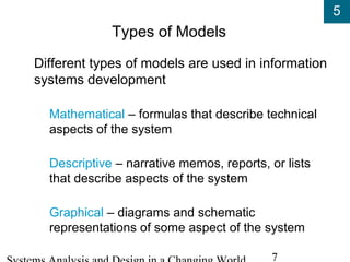
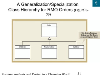
The document discusses models and modeling techniques used in systems analysis and design. It describes three types of models - mathematical, descriptive, and graphical. Key steps in analysis include identifying events that trigger use cases and important "things" in the problem domain. Events are categorized as external, temporal, or state events. Use cases and an event table are used to define system requirements. Traditional approaches use entity-relationship diagrams to model data entities and relationships, while object-oriented approaches use UML class diagrams to model classes, attributes, and associations.
2. 5
2
Learning Objectives
Explain the many reasons for creating information
system models
Describe three types of models and list some
specific models used for analysis and design
Explain how events can be used to define
activities and use cases
Identify and analyze events to which a system
responds
3. 5
3
Learning Objectives (continued)
Explain how the concept of “things” in the
problem domain also defines requirements
Explain the similarities and the differences
between data entities and objects
Identify and analyze data entities and domain
classes needed in the system
Read, interpret, and create an entity-relationship
diagram
Read, interpret, and create a class diagram
4. 5
4
Overview
Document functional requirements by creating
models
Models created during analysis phase activity –
Define system requirements
Two concepts help identify functional
requirements in the traditional approach and
object-oriented approach
Events that trigger use cases
Things in the users’ work domain
5. 5
5
Models and Modeling
Analyst describes information system
requirements using a collection of models
Complex systems require more than one type of
model
Models represent some aspect of the system
being built
Process of creating models helps analyst clarify
and refine design
Models assist communication with system users
7. 5
7
Types of Models
Different types of models are used in information
systems development
Mathematical – formulas that describe technical
aspects of the system
Descriptive – narrative memos, reports, or lists
that describe aspects of the system
Graphical – diagrams and schematic
representations of some aspect of the system
9. 5
9
Overview of Models Used
in Analysis and Design
Analysis phase activity named “define system
requirements”
Logical models
Provide detail without regard to specific technology
Design phase
Physical models
Provide technical details
Extend logical models
12. 5
12
Events, Activities, and Use Cases
Use Case
An activity the system performs in response to a user request
A “case” where the system is used by actor
Techniques for identifying use cases
Identify user goals
Each goal at the elementary business process (EBP) level is a use
case
EBP – a task performed by one user, in one place in response to a
business event, that adds measurable business value, and leaves
system and data in consistent state
Event decomposition technique
CRUD analysis technique (create, read, update, delete)
14. 5
14
Event Decomposition
Business events trigger elementary business
processes (EBPs)
EBPs are at correct level of analysis for use
cases
Identify business events to decompose system
into activities/use cases
Event decomposition is, therefore, used by
Traditional approach to identify activities
OO approach to identify use cases
15. 5
15
Types of Events
External
Outside system
Initiated by external agent or actor
Temporal
Occur as result of reaching a point in time
Based on system deadlines
State
Something inside system triggers processing need
16. 5
16
Events Affecting a Charge Account Processing
System that Lead to Use Cases (Figure 5-7)
19. 5
19
Identifying Events
Can be difficult to determine
Often confused with conditions and responses
May be useful to trace a transaction’s life cycle
Certain events left to design phase
System controls to protect system integrity
Perfect technology assumption defers events
23. 5
23
Events in the RMO case
Important external events involve customers
Customer checks item availability, customer
places order, customer changes or cancels order
Other external events involve departments
Shipping fulfills order, marketing sends promotion
to customer, merchandising updates catalog
Temporal events include periodic reports
Time to produce order summary reports, Time to
produce fulfillment summary reports
24. 5
24
Information about Each Event
in an Event Table:
Catalog of Information about Each Use Case (Figure 5-15)
26. 5
26
“Things” in the Problem Domain
Define system requirements by understanding
system information that needs to be stored
Store information about things in the problem
domain that people deal with when they do their
work
Analysts identify these types of things by
considering each use case in the event table
What things does the system need to know about
and store information about?
28. 5
28
Procedure for Developing an
Initial List of Things
Step 1: Using the event table and information about each
use case, identify all nouns
Step 2: Using other information from existing systems,
current procedures, and current reports or forms, add
items or categories of information needed
Step 3: Refine list and record assumptions or issues to
explore
See Figure 5-18 for RMO example
29. 5
29
Characteristics of Things
Relationship
Naturally occurring association among specific
things
Occur in two directions
Number of associations is cardinality or multiplicity
Binary, unary, ternary, n-ary
Attribute
One specific piece of information about a thing
33. 5
33
Data Entities
Things system needs to store data about in
traditional IS approach
Modeled with entity-relationship diagram (ERD)
Requirements model used to create the database
design model for relational database
34. 5
34
Objects
Objects do the work in a system and store
information in the object-oriented approach
Objects have behaviors and attributes
Class – type of thing
Object – each specific thing
Methods – behaviors of objects of the class
Objects contain values for attributes and methods
for operating on those attributes
An object is encapsulated – a self-contained unit
43. 5
43
The Class Diagram
Unified Modeling Language (UML) diagram
Domain model class diagram
Models things in the users’ work domain
Used to define requirements for OO (very similar
to entities in ERD)
Design class diagram
Models software classes
Adds methods as behaviors
Used in the design activity
45. 5
45
Simple Domain Model Class Diagram
(Figure 5-31)
No methods shown in domain model
Domain classes are not software classes
Very similar to ERD in Figure 5-25
UML and domain model can be used in place of ERD in traditional approach
49. 5
49
More Complex Class Concepts
Generalization/specialization hierarchies
General superclasses to specialized subclasses
Inheritance allows subclasses to share
characteristics of their superclasses
Whole-part hierarchies (object and its parts)
Aggregation – parts can exist separately
Composition – parts can’t exist separately
Hand has fingers and thumb
58. 5
58
Summary
Analysis phase – defines system requirements
Models created to further learning process,
reduce complexity, communicate with team
members, and document requirements
Many types of models used
Mathematical, descriptive, graphical
Key early step in modeling is to identify and list
Events that require a use case in the system
Things users deal with in work environment
59. 5
59
Summary (continued)
Use cases (activities) are identified from user
goals and business events that trigger
elementary business processes
Business events are memorable, can be
described, and occur at a specific time and place
External events, temporal events, and state events
Event table records event, trigger, source, use
case, response, and destination
A catalog of information about each use case
60. 5
60
Summary (continued)
“Things” are what user deals with and system
remembers, such as customer placing an order
Traditional approach uses entity-relationship
diagrams (ERD) for data entities, attributes of
data entities, and relationships between entities
Object-oriented approach uses UML class
diagrams for classes, attributes, methods of
class, and associations among classes
Domain model class diagram (requirements activity)
Design class diagram (design activity)