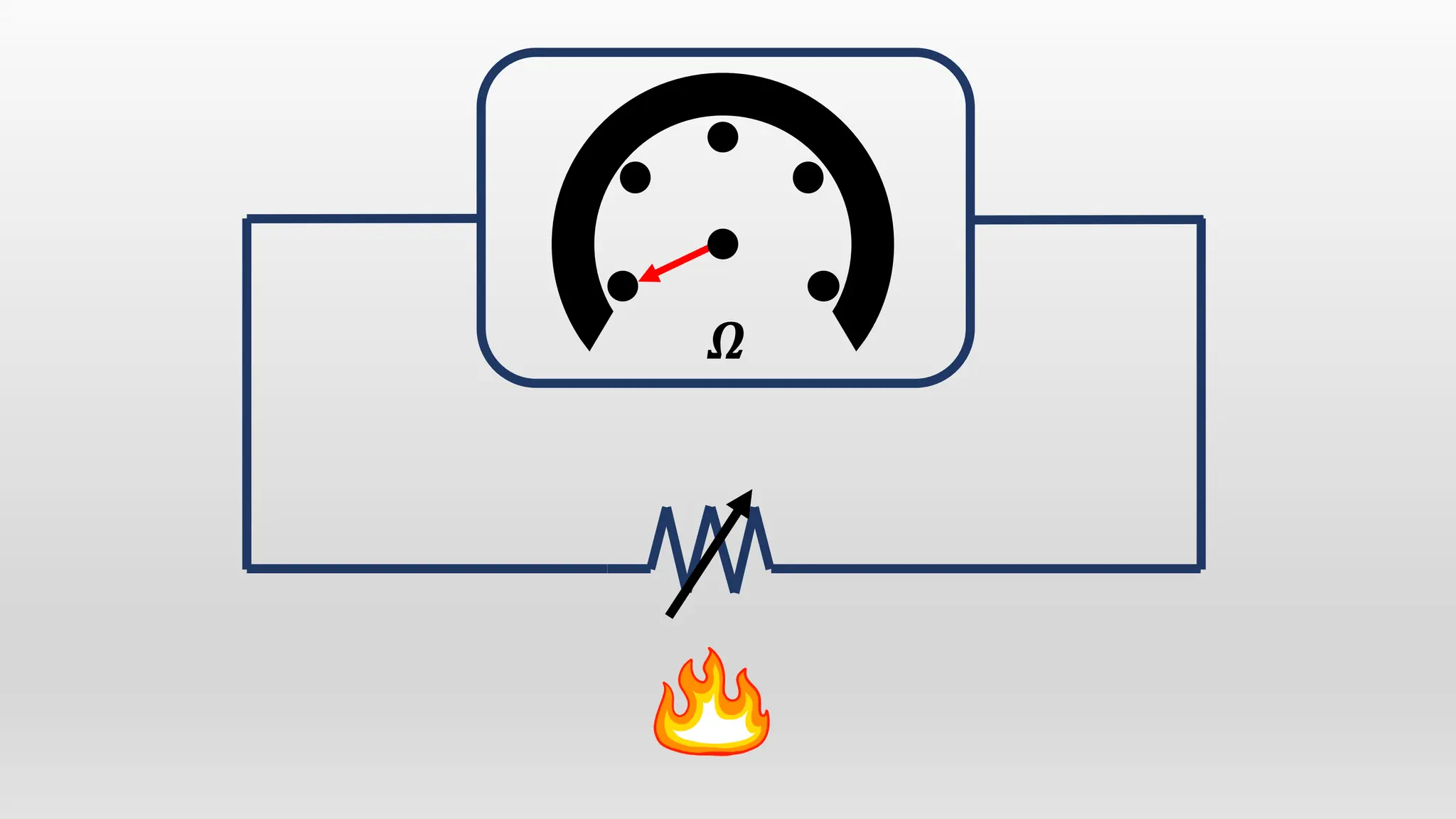
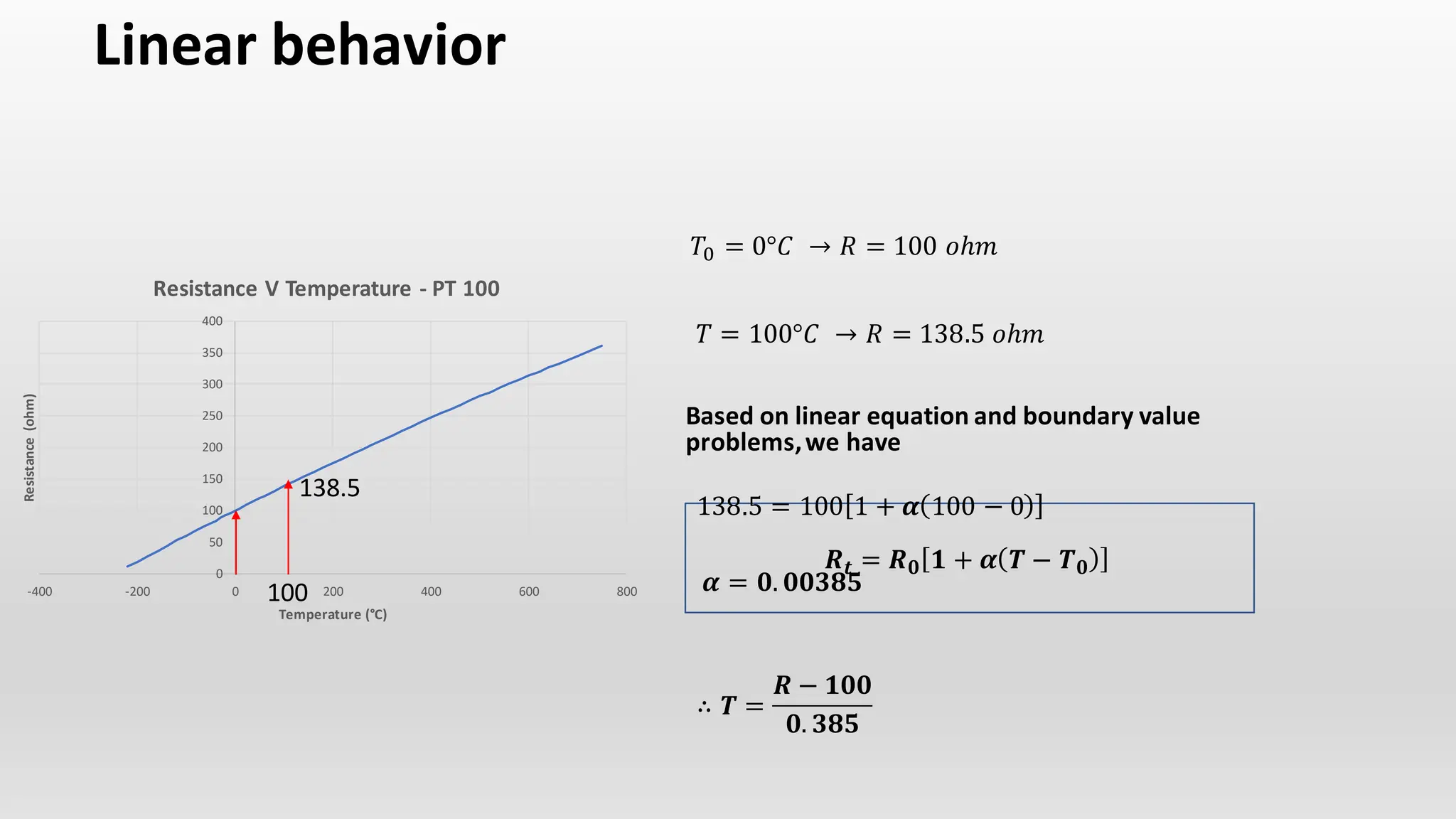
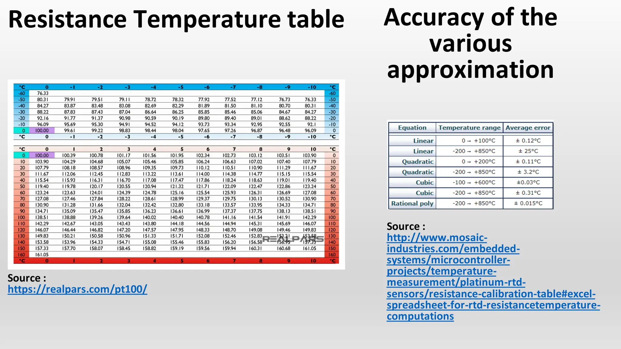
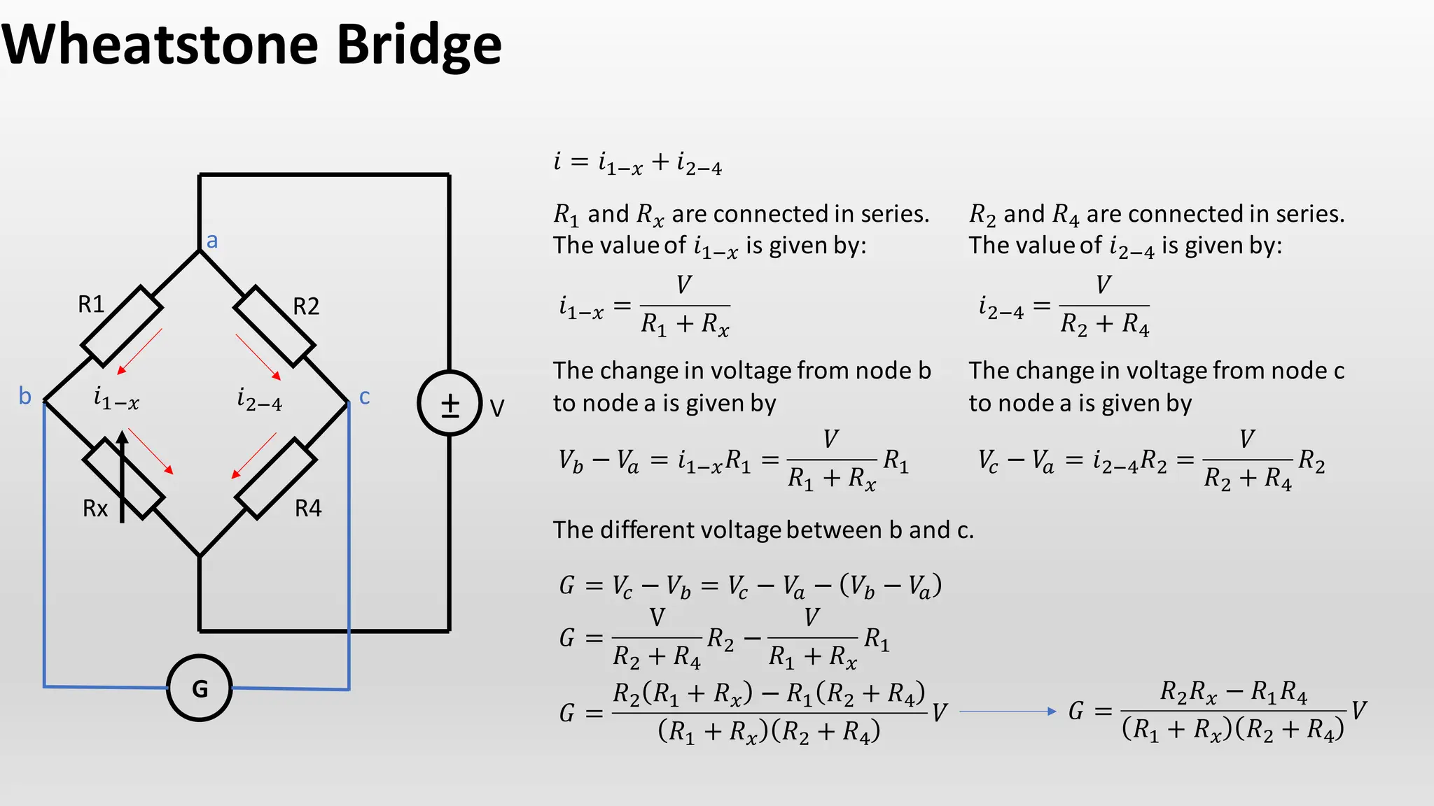
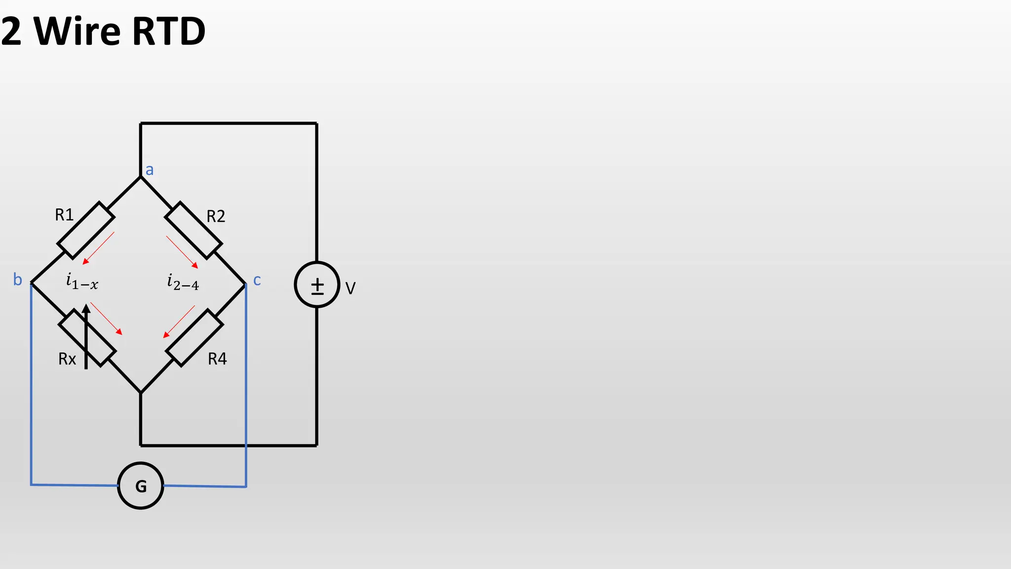
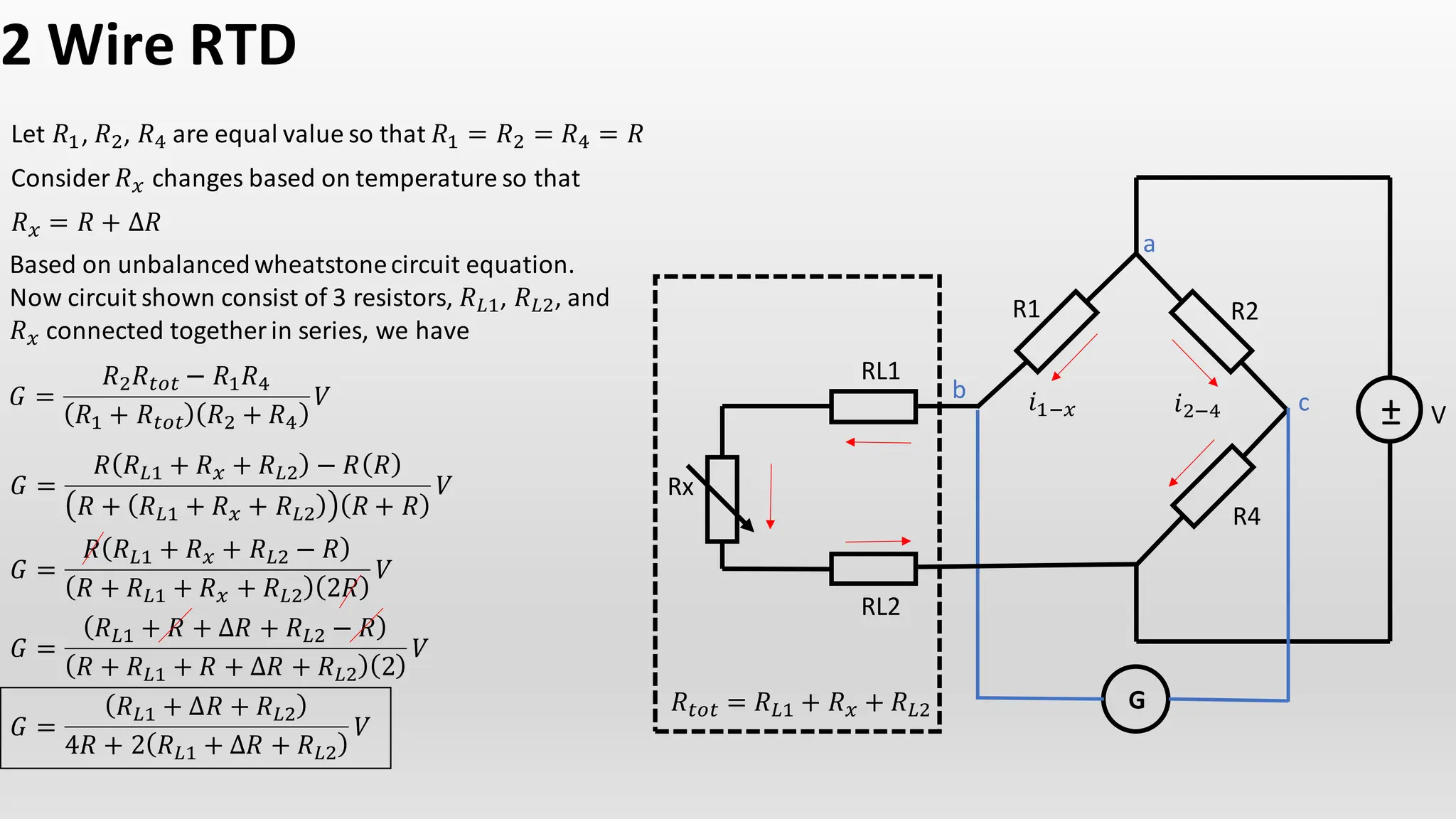
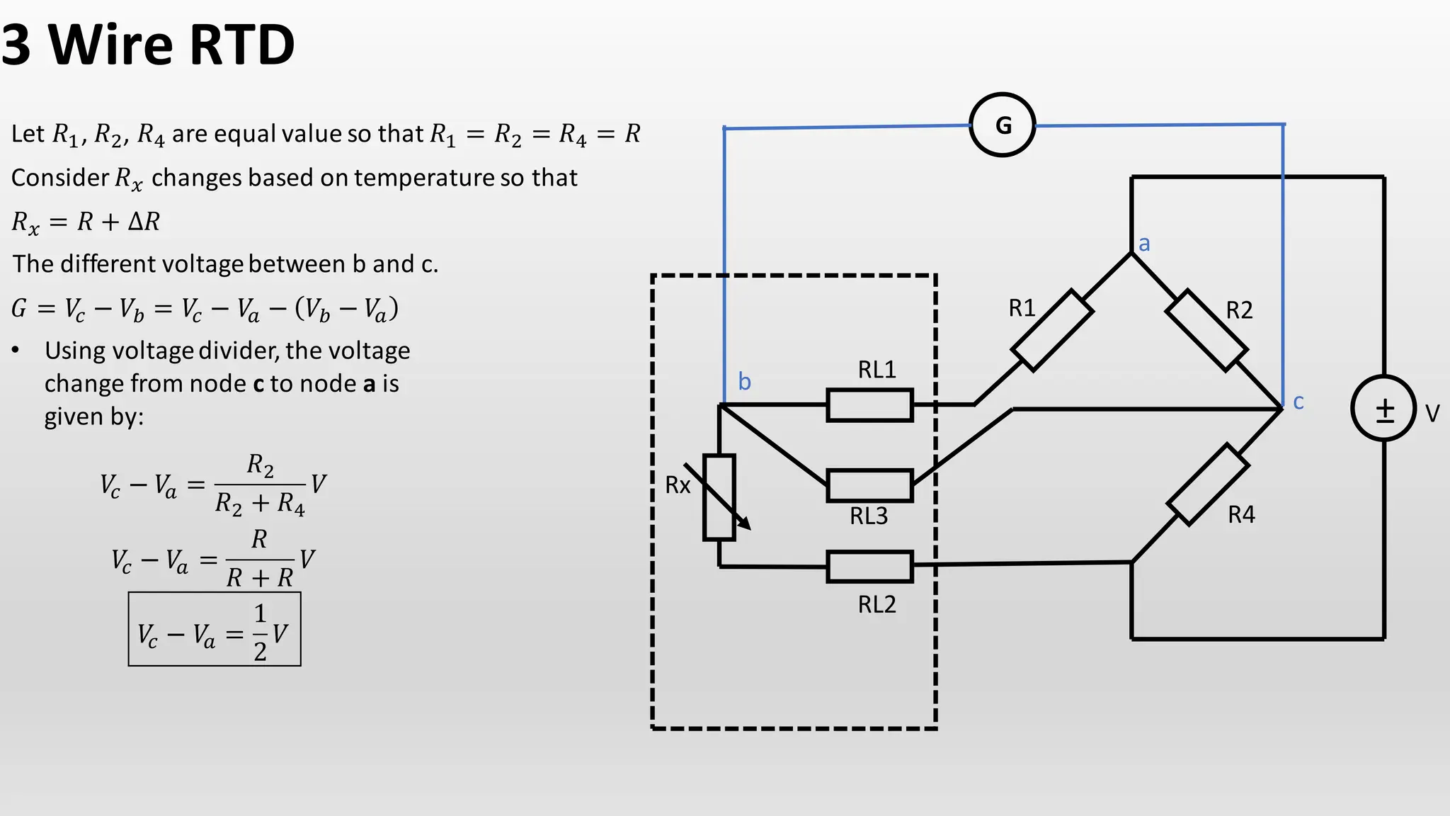
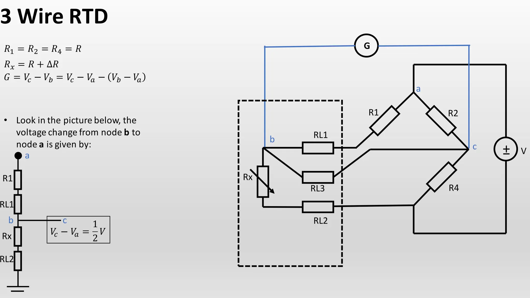
Created by:
M.Dije
RTD (Resitance
Temperature
Detector)
𝜴
RTD Characteristic
𝑅𝑡 = 𝑅0 1 + 𝛼 𝑇 − 𝑇0 + 𝛽 𝑇 − 𝑇0 + …
𝑹𝒕 = 𝑹𝟎 𝟏 + 𝜶 𝑻 − 𝑻𝟎
0
50
100
150
200
250
300
350
400
-400 -200 0 200 400 600 800
Resistance
(ohm)
Temperature (°C)
Resistance V Temperature - PT 100
𝑇0 = 0°𝐶 → 𝑅 = 100 𝑜ℎ𝑚
100
138.5
𝑇 = 100°𝐶 → 𝑅 = 138.5 𝑜ℎ𝑚
Based on linear equation and boundary value
problems,we have
138.5 = 100 1 + 𝜶 100 − 0
𝜶 = 𝟎. 𝟎𝟎𝟑𝟖𝟓
Linear behavior
∴ 𝑻 =
𝑹 − 𝟏𝟎𝟎
𝟎. 𝟑𝟖𝟓
Resistance Temperature table Accuracy of the
various
approximation
Source :
https://realpars.com/pt100/
Source :
http://www.mosaic-
industries.com/embedded-
systems/microcontroller-
projects/temperature-
measurement/platinum-rtd-
sensors/resistance-calibration-table#excel-
spreadsheet-for-rtd-resistancetemperature-
computations
Construction of a RTD
Wheatstone Bridge
G
±
R1 R2
Rx R4
a
b c
𝑖1−𝑥 𝑖2−4
𝑖 = 𝑖1−𝑥 + 𝑖2−4
𝑅1 and 𝑅𝑥 are connected in series.
The valueof 𝑖1−𝑥 is given by:
𝑅2 and 𝑅4 are connected in series.
The valueof 𝑖2−4 is given by:
𝑖1−𝑥 =
𝑉
𝑅1 + 𝑅𝑥
V
𝑖2−4 =
𝑉
𝑅2 + 𝑅4
The change in voltage from node b
to node a is given by
𝑉𝑏 − 𝑉
𝑎 = 𝑖1−𝑥𝑅1 =
𝑉
𝑅1 + 𝑅𝑥
𝑅1 𝑉
𝑐 − 𝑉
𝑎 = 𝑖2−4𝑅2 =
𝑉
𝑅2 + 𝑅4
𝑅2
The different voltagebetween b and c.
𝐺 = 𝑉
𝑐 − 𝑉𝑏 = 𝑉
𝑐 − 𝑉
𝑎 − 𝑉𝑏 − 𝑉
𝑎
The change in voltage from node c
to node a is given by
𝐺 =
V
𝑅2 + 𝑅4
𝑅2 −
𝑉
𝑅1 + 𝑅𝑥
𝑅1
𝐺 =
𝑅2 𝑅1 + 𝑅𝑥 − 𝑅1 𝑅2 + 𝑅4
𝑅1 + 𝑅𝑥 𝑅2 + 𝑅4
𝑉 𝐺 =
𝑅2𝑅𝑥 − 𝑅1𝑅4
𝑅1 + 𝑅𝑥 𝑅2 + 𝑅4
𝑉
Wheatstone Bridge
G
±
R1 R2
Rx R4
a
b c
𝑖1−𝑥 𝑖2−4 V
𝐺 =
𝑅2𝑅𝑥 − 𝑅1𝑅4
𝑅1 + 𝑅𝑥 𝑅2 + 𝑅4
𝑉
When this happen the parallelnetwork is said to be unbalanced as the
voltage at point b is at different value to the voltageat point c.
Something else equally as important is that the voltage difference between
point b and point c will be zerovolts as both points are at the same value.
When this happens, both sides of the parallelbridge network are said to
be balanced.
In balanced conditionthe numerator of the function equal to zero.
𝑅2𝑅𝑥 − 𝑅1𝑅4 = 0
𝑅2𝑅𝑥 = 𝑅1𝑅4
𝑅1
𝑅3
=
𝑅2
𝑅4
2 Wire RTD
G
±
R1 R2
Rx R4
a
b c
𝑖1−𝑥 𝑖2−4 V
2 Wire RTD
G
±
R1 R2
Rx R4
a
b c
𝑖1−𝑥 𝑖2−4 V
2 Wire RTD
G
±
R1 R2
R4
a
b c
𝑖1−𝑥 𝑖2−4 V
Rx
RL1
RL2
𝑅𝑡𝑜𝑡 = 𝑅𝐿1 + 𝑅𝑥 + 𝑅𝐿2
Let 𝑅1, 𝑅2, 𝑅4 are equal value so that 𝑅1 = 𝑅2 = 𝑅4 = 𝑅
Consider 𝑅𝑥 changes based on temperature so that
𝑅𝑥 = 𝑅 + ∆𝑅
Based on unbalanced wheatstonecircuit equation.
Now circuit shown consist of 3 resistors, 𝑅𝐿1, 𝑅𝐿2, and
𝑅𝑥 connected together in series, we have
𝐺 =
𝑅2𝑅𝑡𝑜𝑡 − 𝑅1𝑅4
𝑅1 + 𝑅𝑡𝑜𝑡 𝑅2 + 𝑅4
𝑉
𝐺 =
𝑅 𝑅𝐿1 + 𝑅𝑥 + 𝑅𝐿2 − 𝑅 𝑅
𝑅 + 𝑅𝐿1 + 𝑅𝑥 + 𝑅𝐿2 𝑅 + 𝑅
𝑉
𝐺 =
𝑅 𝑅𝐿1 + 𝑅𝑥 + 𝑅𝐿2 − 𝑅
𝑅 + 𝑅𝐿1 + 𝑅𝑥 + 𝑅𝐿2 2𝑅
𝑉
𝐺 =
𝑅𝐿1 + 𝑅 + ∆𝑅 + 𝑅𝐿2 − 𝑅
𝑅 + 𝑅𝐿1 + 𝑅 + ∆𝑅 + 𝑅𝐿2 2
𝑉
𝐺 =
𝑅𝐿1 + ∆𝑅 + 𝑅𝐿2
4𝑅 + 2 𝑅𝐿1 + ∆𝑅 + 𝑅𝐿2
𝑉
2 Wire RTD
G
±
R1 R2
R4
a
b c
𝑖1−𝑥 𝑖2−4 V
Rx
RL1
RL2
𝑅𝑡𝑜𝑡 = 𝑅𝐿1 + 𝑅𝑥 + 𝑅𝐿2
𝐺 =
𝑅𝐿1 + ∆𝑅 + 𝑅𝐿2
4𝑅 + 2 𝑅𝐿1 + ∆𝑅 + 𝑅𝐿2
𝑉
Suppose that 𝑅𝐿1 = 𝑅𝐿2 = 𝑅𝐿
𝐺 =
∆𝑅 + 2𝑅𝐿
4𝑅 + 2 2𝑅𝐿 + ∆𝑅
𝑉
3 Wire RTD
±
G
R1 R2
R4
a
b
c V
Rx
RL1
RL2
RL3
Let 𝑅1, 𝑅2, 𝑅4 are equal value so that 𝑅1 = 𝑅2 = 𝑅4 = 𝑅
Consider 𝑅𝑥 changes based on temperature so that
𝑅𝑥 = 𝑅 + ∆𝑅
The different voltagebetween b and c.
𝐺 = 𝑉
𝑐 − 𝑉𝑏 = 𝑉
𝑐 − 𝑉
𝑎 − 𝑉𝑏 − 𝑉
𝑎
• Using voltagedivider, the voltage
change from node c to node a is
given by:
𝑉
𝑐 − 𝑉
𝑎 =
𝑅2
𝑅2 + 𝑅4
𝑉
𝑉
𝑐 − 𝑉
𝑎 =
𝑅
𝑅 + 𝑅
𝑉
𝑉
𝑐 − 𝑉
𝑎 =
1
2
𝑉
3 Wire RTD
±
G
R1 R2
R4
a
b
c V
Rx
RL1
RL2
RL3
𝑅1 = 𝑅2 = 𝑅4 = 𝑅
𝑅𝑥 = 𝑅 + ∆𝑅
𝐺 = 𝑉
𝑐 − 𝑉𝑏 = 𝑉
𝑐 − 𝑉
𝑎 − 𝑉𝑏 − 𝑉
𝑎
𝑉
𝑐 − 𝑉
𝑎 =
1
2
𝑉
• Look in the picture below, the
voltage change from node b to
node a is given by:
a
b c
R1
RL1
Rx
RL2
THANKS

RTD basic concept for Instrumentation and Electrical

  • 1.
  • 2.
  • 3.
    RTD Characteristic 𝑅𝑡 =𝑅0 1 + 𝛼 𝑇 − 𝑇0 + 𝛽 𝑇 − 𝑇0 + … 𝑹𝒕 = 𝑹𝟎 𝟏 + 𝜶 𝑻 − 𝑻𝟎
  • 4.
    𝑹𝒕 = 𝑹𝟎𝟏 + 𝜶 𝑻 − 𝑻𝟎 0 50 100 150 200 250 300 350 400 -400 -200 0 200 400 600 800 Resistance (ohm) Temperature (°C) Resistance V Temperature - PT 100 𝑇0 = 0°𝐶 → 𝑅 = 100 𝑜ℎ𝑚 100 138.5 𝑇 = 100°𝐶 → 𝑅 = 138.5 𝑜ℎ𝑚 Based on linear equation and boundary value problems,we have 138.5 = 100 1 + 𝜶 100 − 0 𝜶 = 𝟎. 𝟎𝟎𝟑𝟖𝟓 Linear behavior ∴ 𝑻 = 𝑹 − 𝟏𝟎𝟎 𝟎. 𝟑𝟖𝟓
  • 5.
    Resistance Temperature tableAccuracy of the various approximation Source : https://realpars.com/pt100/ Source : http://www.mosaic- industries.com/embedded- systems/microcontroller- projects/temperature- measurement/platinum-rtd- sensors/resistance-calibration-table#excel- spreadsheet-for-rtd-resistancetemperature- computations
  • 6.
  • 7.
    Wheatstone Bridge G ± R1 R2 RxR4 a b c 𝑖1−𝑥 𝑖2−4 𝑖 = 𝑖1−𝑥 + 𝑖2−4 𝑅1 and 𝑅𝑥 are connected in series. The valueof 𝑖1−𝑥 is given by: 𝑅2 and 𝑅4 are connected in series. The valueof 𝑖2−4 is given by: 𝑖1−𝑥 = 𝑉 𝑅1 + 𝑅𝑥 V 𝑖2−4 = 𝑉 𝑅2 + 𝑅4 The change in voltage from node b to node a is given by 𝑉𝑏 − 𝑉 𝑎 = 𝑖1−𝑥𝑅1 = 𝑉 𝑅1 + 𝑅𝑥 𝑅1 𝑉 𝑐 − 𝑉 𝑎 = 𝑖2−4𝑅2 = 𝑉 𝑅2 + 𝑅4 𝑅2 The different voltagebetween b and c. 𝐺 = 𝑉 𝑐 − 𝑉𝑏 = 𝑉 𝑐 − 𝑉 𝑎 − 𝑉𝑏 − 𝑉 𝑎 The change in voltage from node c to node a is given by 𝐺 = V 𝑅2 + 𝑅4 𝑅2 − 𝑉 𝑅1 + 𝑅𝑥 𝑅1 𝐺 = 𝑅2 𝑅1 + 𝑅𝑥 − 𝑅1 𝑅2 + 𝑅4 𝑅1 + 𝑅𝑥 𝑅2 + 𝑅4 𝑉 𝐺 = 𝑅2𝑅𝑥 − 𝑅1𝑅4 𝑅1 + 𝑅𝑥 𝑅2 + 𝑅4 𝑉
  • 8.
    Wheatstone Bridge G ± R1 R2 RxR4 a b c 𝑖1−𝑥 𝑖2−4 V 𝐺 = 𝑅2𝑅𝑥 − 𝑅1𝑅4 𝑅1 + 𝑅𝑥 𝑅2 + 𝑅4 𝑉 When this happen the parallelnetwork is said to be unbalanced as the voltage at point b is at different value to the voltageat point c. Something else equally as important is that the voltage difference between point b and point c will be zerovolts as both points are at the same value. When this happens, both sides of the parallelbridge network are said to be balanced. In balanced conditionthe numerator of the function equal to zero. 𝑅2𝑅𝑥 − 𝑅1𝑅4 = 0 𝑅2𝑅𝑥 = 𝑅1𝑅4 𝑅1 𝑅3 = 𝑅2 𝑅4
  • 9.
    2 Wire RTD G ± R1R2 Rx R4 a b c 𝑖1−𝑥 𝑖2−4 V
  • 10.
    2 Wire RTD G ± R1R2 Rx R4 a b c 𝑖1−𝑥 𝑖2−4 V
  • 11.
    2 Wire RTD G ± R1R2 R4 a b c 𝑖1−𝑥 𝑖2−4 V Rx RL1 RL2 𝑅𝑡𝑜𝑡 = 𝑅𝐿1 + 𝑅𝑥 + 𝑅𝐿2 Let 𝑅1, 𝑅2, 𝑅4 are equal value so that 𝑅1 = 𝑅2 = 𝑅4 = 𝑅 Consider 𝑅𝑥 changes based on temperature so that 𝑅𝑥 = 𝑅 + ∆𝑅 Based on unbalanced wheatstonecircuit equation. Now circuit shown consist of 3 resistors, 𝑅𝐿1, 𝑅𝐿2, and 𝑅𝑥 connected together in series, we have 𝐺 = 𝑅2𝑅𝑡𝑜𝑡 − 𝑅1𝑅4 𝑅1 + 𝑅𝑡𝑜𝑡 𝑅2 + 𝑅4 𝑉 𝐺 = 𝑅 𝑅𝐿1 + 𝑅𝑥 + 𝑅𝐿2 − 𝑅 𝑅 𝑅 + 𝑅𝐿1 + 𝑅𝑥 + 𝑅𝐿2 𝑅 + 𝑅 𝑉 𝐺 = 𝑅 𝑅𝐿1 + 𝑅𝑥 + 𝑅𝐿2 − 𝑅 𝑅 + 𝑅𝐿1 + 𝑅𝑥 + 𝑅𝐿2 2𝑅 𝑉 𝐺 = 𝑅𝐿1 + 𝑅 + ∆𝑅 + 𝑅𝐿2 − 𝑅 𝑅 + 𝑅𝐿1 + 𝑅 + ∆𝑅 + 𝑅𝐿2 2 𝑉 𝐺 = 𝑅𝐿1 + ∆𝑅 + 𝑅𝐿2 4𝑅 + 2 𝑅𝐿1 + ∆𝑅 + 𝑅𝐿2 𝑉
  • 12.
    2 Wire RTD G ± R1R2 R4 a b c 𝑖1−𝑥 𝑖2−4 V Rx RL1 RL2 𝑅𝑡𝑜𝑡 = 𝑅𝐿1 + 𝑅𝑥 + 𝑅𝐿2 𝐺 = 𝑅𝐿1 + ∆𝑅 + 𝑅𝐿2 4𝑅 + 2 𝑅𝐿1 + ∆𝑅 + 𝑅𝐿2 𝑉 Suppose that 𝑅𝐿1 = 𝑅𝐿2 = 𝑅𝐿 𝐺 = ∆𝑅 + 2𝑅𝐿 4𝑅 + 2 2𝑅𝐿 + ∆𝑅 𝑉
  • 13.
    3 Wire RTD ± G R1R2 R4 a b c V Rx RL1 RL2 RL3 Let 𝑅1, 𝑅2, 𝑅4 are equal value so that 𝑅1 = 𝑅2 = 𝑅4 = 𝑅 Consider 𝑅𝑥 changes based on temperature so that 𝑅𝑥 = 𝑅 + ∆𝑅 The different voltagebetween b and c. 𝐺 = 𝑉 𝑐 − 𝑉𝑏 = 𝑉 𝑐 − 𝑉 𝑎 − 𝑉𝑏 − 𝑉 𝑎 • Using voltagedivider, the voltage change from node c to node a is given by: 𝑉 𝑐 − 𝑉 𝑎 = 𝑅2 𝑅2 + 𝑅4 𝑉 𝑉 𝑐 − 𝑉 𝑎 = 𝑅 𝑅 + 𝑅 𝑉 𝑉 𝑐 − 𝑉 𝑎 = 1 2 𝑉
  • 14.
    3 Wire RTD ± G R1R2 R4 a b c V Rx RL1 RL2 RL3 𝑅1 = 𝑅2 = 𝑅4 = 𝑅 𝑅𝑥 = 𝑅 + ∆𝑅 𝐺 = 𝑉 𝑐 − 𝑉𝑏 = 𝑉 𝑐 − 𝑉 𝑎 − 𝑉𝑏 − 𝑉 𝑎 𝑉 𝑐 − 𝑉 𝑎 = 1 2 𝑉 • Look in the picture below, the voltage change from node b to node a is given by: a b c R1 RL1 Rx RL2
  • 15.