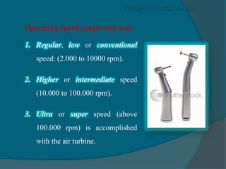
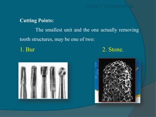
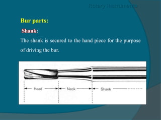
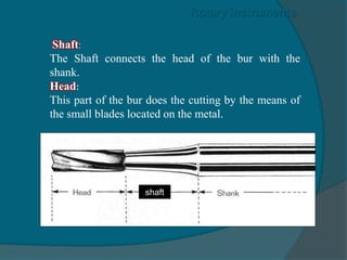
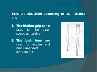
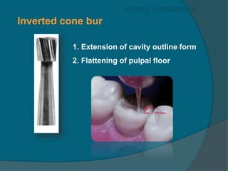
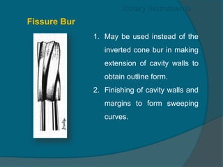
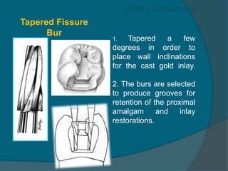
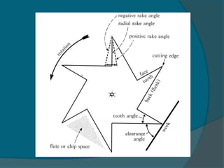
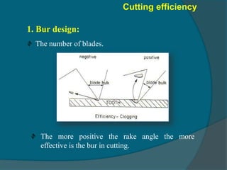
Rotary
instruments
Operating Speed ranges and uses:
1. Regular, low or conventional
speed: (2.000 to 10000 rpm).
2. Higher or intermediate speed
(10.000 to 100.000 rpm).
3. Ultra or super speed (above
100.000 rpm) is accomplished
with the air turbine.
Rotary instruments
Cutting Points:
The smallest unit and the one actually removing
tooth structures, may be one of two:
1. Bur 2. Stone.
Rotary instruments
Bur parts:
Shank:
The shank is secured to the hand piece for the purpose
of driving the bur.
Rotary instruments
Shaft:
The Shaft connects the head of the bur with the
shank.
Head:
This part of the bur does the cutting by the means of
the small blades located on the metal.
Rotary instruments
shaft
Burs are classified according to their shanks
into:
Rotary instruments
1. The friction-grip bur is
used for the ultra-
speed air turbine.
2. The latch type: are
used for regular and
medium-speed
instruments.
Round bur
1.Gainig access.
2.Excavation of caries.
Rotary instruments
Inverted cone bur
1. Extension of cavity outline form
2. Flattening of pulpal floor
Rotary instruments
1. May be used instead of the
inverted cone bur in making
extension of cavity walls to
obtain outline form.
2. Finishing of cavity walls and
margins to form sweeping
curves.
Fissure Bur
Rotary instruments
1. Tapered a few
degrees in order to
place wall inclinations
for the cast gold inlay.
2. The burs are selected
to produce grooves for
retention of the proximal
amalgam and inlay
restorations.
Rotary instruments
Tapered Fissure
Bur
The blades are shorter and closer
together than in other burs.
They are used for finishing and
polishing of metallic restorations.
Rotary instruments
Finishing bur
Design of dental bur:
The bur head may be
divided into 6 or 8 blades
(also called teeth, flutes).
Each flute or blade has a
leading side “Face”, and a
trailing side “Back” with
an angle in between, called
the “flute Angle” or blade
angle.
Bur Design
Clearance
angle
Clearance Angle:
It is the angle between the
back of the blade and the
“work”
It acts to decrease the
friction between the back
of bur blade and the work
or tooth tissues during
cutting, and therefore,
decrease heat generation.
Bur Design
Clearance
angle
Clearance or Chip Space:.
The space between each two
successive blades
A space where the chips
formed during the cutting
procedures collect and get
eliminated.
Too small, the formed chips
will remain in-between the
bur blades, causing its
clogging generation of more
heat and loss of
effectiveness.
Bur Design
Clearance
angle
Bur Design
Rake Angle:
An angle created between the face of the blade with the
radius of the bur .
The rake angle may be positive, Zero (radial), and
negative, depending on whether the radial line is ahead,
over-lying. Or tailing the face of the blade respectively.
Bur Design
Radius
where the radial line is ahead to the
face of the blade.
A positive rake angle enables the blade
to cut more effectively.
making the rake angle more positive
can only be attained by thinning out the
blade.
This will cause the blade to become
weak and to turn and lose its
effectiveness quite more rapidly.
Bur Design
Bur Design
Zero Rake Angle: where the
radial line is over-lying the face
of the blade.
A positive rake angle enables
the blade to cut more effectively
than a zero one.
Bur Design
Radius
Negative rake angle: where the
radial line is tailing the face of
the blade.
A positive rake angle enables
the blade to cut more effectively
than a negative one.
Cutting efficiency:
It is the ability of the instrument to remove a
maximum amount of tooth tissues with a minimum of
effort and time involved.
Cutting efficiency
Factors influencing the cutting efficiency of burs:
1. Bur design.
2. Composition of the bur.
3. Tissues to be cut.
1. Bur design:
The number of blades.
Cutting efficiency
The more positive the rake angle the more
effective is the bur in cutting.

Rotary instruments for dentistry students

  • 1.
  • 2.
    Operating Speed rangesand uses: 1. Regular, low or conventional speed: (2.000 to 10000 rpm). 2. Higher or intermediate speed (10.000 to 100.000 rpm). 3. Ultra or super speed (above 100.000 rpm) is accomplished with the air turbine. Rotary instruments
  • 3.
    Cutting Points: The smallestunit and the one actually removing tooth structures, may be one of two: 1. Bur 2. Stone. Rotary instruments
  • 4.
    Bur parts: Shank: The shankis secured to the hand piece for the purpose of driving the bur. Rotary instruments
  • 5.
    Shaft: The Shaft connectsthe head of the bur with the shank. Head: This part of the bur does the cutting by the means of the small blades located on the metal. Rotary instruments shaft
  • 6.
    Burs are classifiedaccording to their shanks into: Rotary instruments 1. The friction-grip bur is used for the ultra- speed air turbine. 2. The latch type: are used for regular and medium-speed instruments.
  • 7.
    Round bur 1.Gainig access. 2.Excavationof caries. Rotary instruments
  • 8.
    Inverted cone bur 1.Extension of cavity outline form 2. Flattening of pulpal floor Rotary instruments
  • 9.
    1. May beused instead of the inverted cone bur in making extension of cavity walls to obtain outline form. 2. Finishing of cavity walls and margins to form sweeping curves. Fissure Bur Rotary instruments
  • 10.
    1. Tapered afew degrees in order to place wall inclinations for the cast gold inlay. 2. The burs are selected to produce grooves for retention of the proximal amalgam and inlay restorations. Rotary instruments Tapered Fissure Bur
  • 11.
    The blades areshorter and closer together than in other burs. They are used for finishing and polishing of metallic restorations. Rotary instruments Finishing bur
  • 12.
    Design of dentalbur: The bur head may be divided into 6 or 8 blades (also called teeth, flutes). Each flute or blade has a leading side “Face”, and a trailing side “Back” with an angle in between, called the “flute Angle” or blade angle. Bur Design Clearance angle
  • 13.
    Clearance Angle: It isthe angle between the back of the blade and the “work” It acts to decrease the friction between the back of bur blade and the work or tooth tissues during cutting, and therefore, decrease heat generation. Bur Design Clearance angle
  • 14.
    Clearance or ChipSpace:. The space between each two successive blades A space where the chips formed during the cutting procedures collect and get eliminated. Too small, the formed chips will remain in-between the bur blades, causing its clogging generation of more heat and loss of effectiveness. Bur Design Clearance angle
  • 15.
  • 16.
    Rake Angle: An anglecreated between the face of the blade with the radius of the bur . The rake angle may be positive, Zero (radial), and negative, depending on whether the radial line is ahead, over-lying. Or tailing the face of the blade respectively. Bur Design
  • 17.
    Radius where the radialline is ahead to the face of the blade. A positive rake angle enables the blade to cut more effectively. making the rake angle more positive can only be attained by thinning out the blade. This will cause the blade to become weak and to turn and lose its effectiveness quite more rapidly. Bur Design
  • 18.
    Bur Design Zero RakeAngle: where the radial line is over-lying the face of the blade. A positive rake angle enables the blade to cut more effectively than a zero one.
  • 19.
    Bur Design Radius Negative rakeangle: where the radial line is tailing the face of the blade. A positive rake angle enables the blade to cut more effectively than a negative one.
  • 21.
    Cutting efficiency: It isthe ability of the instrument to remove a maximum amount of tooth tissues with a minimum of effort and time involved. Cutting efficiency Factors influencing the cutting efficiency of burs: 1. Bur design. 2. Composition of the bur. 3. Tissues to be cut.
  • 22.
    1. Bur design: Thenumber of blades. Cutting efficiency The more positive the rake angle the more effective is the bur in cutting.