SlideShare a Scribd company logo
1 of 9
Download to read offline
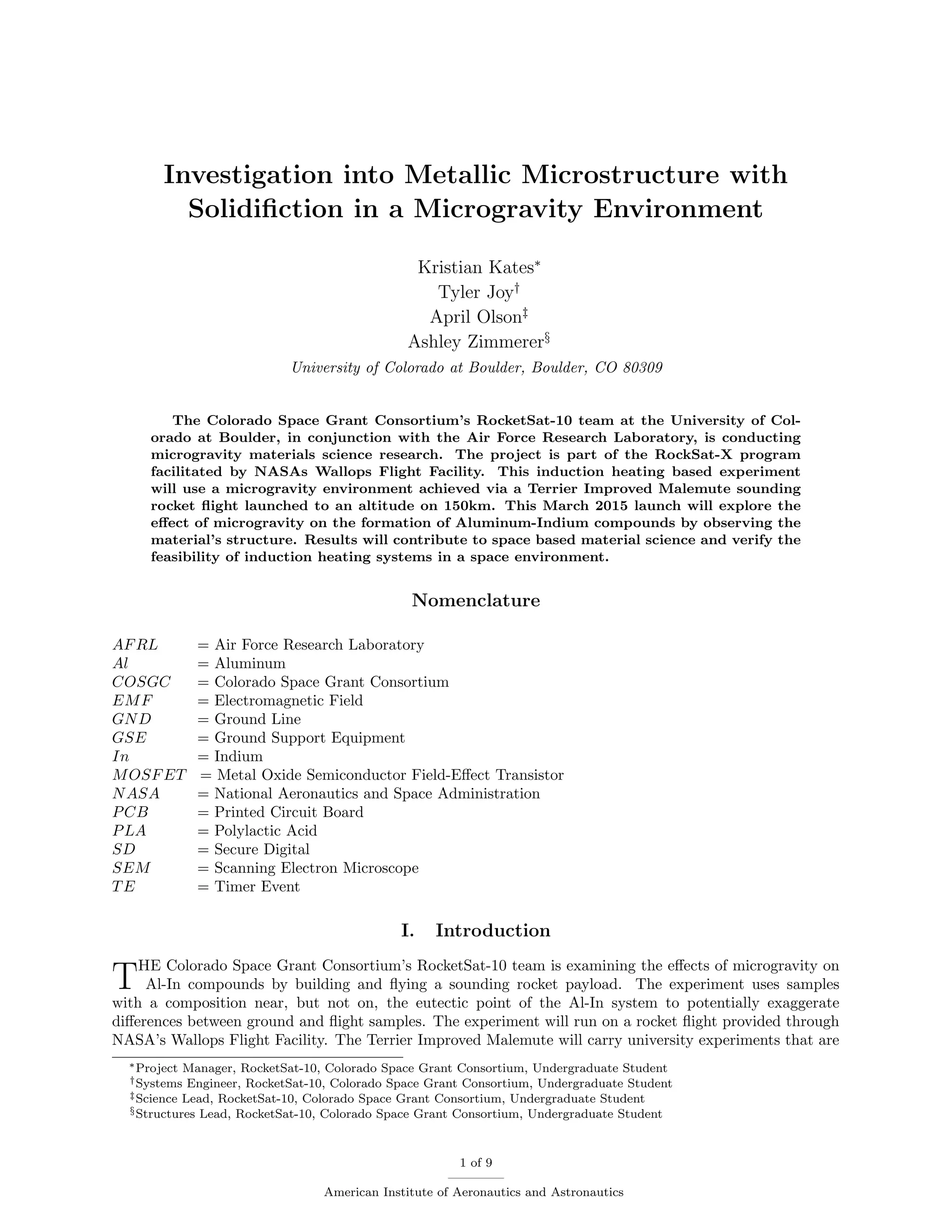
Investigation into Metallic Microstructure with
Solidifiction in a Microgravity Environment
Kristian Kates∗
Tyler Joy†
April Olson‡
Ashley Zimmerer§
University of Colorado at Boulder, Boulder, CO 80309
The Colorado Space Grant Consortium’s RocketSat-10 team at the University of Col-
orado at Boulder, in conjunction with the Air Force Research Laboratory, is conducting
microgravity materials science research. The project is part of the RockSat-X program
facilitated by NASAs Wallops Flight Facility. This induction heating based experiment
will use a microgravity environment achieved via a Terrier Improved Malemute sounding
rocket flight launched to an altitude on 150km. This March 2015 launch will explore the
effect of microgravity on the formation of Aluminum-Indium compounds by observing the
material’s structure. Results will contribute to space based material science and verify the
feasibility of induction heating systems in a space environment.
Nomenclature
AFRL = Air Force Research Laboratory
Al = Aluminum
COSGC = Colorado Space Grant Consortium
EMF = Electromagnetic Field
GND = Ground Line
GSE = Ground Support Equipment
In = Indium
MOSFET = Metal Oxide Semiconductor Field-Effect Transistor
NASA = National Aeronautics and Space Administration
PCB = Printed Circuit Board
PLA = Polylactic Acid
SD = Secure Digital
SEM = Scanning Electron Microscope
TE = Timer Event
I. Introduction
THE Colorado Space Grant Consortium’s RocketSat-10 team is examining the effects of microgravity on
Al-In compounds by building and flying a sounding rocket payload. The experiment uses samples
with a composition near, but not on, the eutectic point of the Al-In system to potentially exaggerate
differences between ground and flight samples. The experiment will run on a rocket flight provided through
NASA’s Wallops Flight Facility. The Terrier Improved Malemute will carry university experiments that are
∗Project Manager, RocketSat-10, Colorado Space Grant Consortium, Undergraduate Student
†Systems Engineer, RocketSat-10, Colorado Space Grant Consortium, Undergraduate Student
‡Science Lead, RocketSat-10, Colorado Space Grant Consortium, Undergraduate Student
§Structures Lead, RocketSat-10, Colorado Space Grant Consortium, Undergraduate Student
1 of 9
American Institute of Aeronautics and Astronautics
participating in the RockSat-X program. Upon reaching space, the rocket will provide limited power to the
payload for 512 seconds from launch through an apogee of 150 kilometers.1
Within this time frame, the
RocketSat-10 payload will run its isolated induction heating system and sensor array; creating and collecting
data on a sample generated in microgravity.
The payload is designed to autonomously run the experiment when given power and timing signals from
the rocket. The control system receives power and begins data collection, then runs the induction system
when given timed signals. The payload protects the system from radiation, out-gassing, vacuum, water,
re-entry heating, and many other aspects of the flight which may harm the system and contaminate the
sample. The system is also supported by the structure for the severe forces of launch and re-entry.
Micro-structures in the sample will be examined for differences between ground and flight samples. SEM
analysis will reveal the chemical makeup of the samples across a plane as well as the micro-structures of the
sample. Multiple data points are necessary to create a large enough data set for conclusive results, therefore
multiple flights may be necessary. However, no future flights are currently scheduled.
II. System Design
Figure 1: Complete system.
This experiment requires a microgravity environment to operate which will be achieved via a stabilized
sounding rocket flight. The flight will have three main stages: launch, flight, and ocean recovery. The payload
is subject to constraints including mass, volume, and power usage limitations. In addition the design must
seal against the vacuum of space and sea water, survive re-entry heating, and intense vibrational loading.
These concerns are addressed in the electrical and mechanical design.
A. Electrical
Electrical, telemetry and time restrictions drove much of the electrical subsystem design and implementation.
Electrical and telemetry restrictions are in place due to requirements specified by the program user manual
and shared payload space. Table 1 below outlines the power pins provided by Wallops Flight Facility through
15-pin power and 37-pin telemetry connectors. Pins not listed within the connector are considered not to be
connected to the payload.
From Table 1, it can be seen that the payload receives a total of 3 power lines across the entirety of the
flight. Each line is activated at certain times during the flight as specified. These times were determined
and finalized in early February. Table 2 refers to each of these activation times and their purposes. Each
2 of 9
American Institute of Aeronautics and Astronautics
Table 1: 15-Pin Power and 37-Pin Telemetry connector pin layout for interface with rocket
Power Pin Power Function Telemetry Pin Telemetry Function
2 Timer Event R1 (TE-RA) 1 Analog Data (Temperature 1)
3 Timer Event R2 (TE-RB) 2 Analog Data (Temperature 2)
9 +28V (GSE 2) 3 Analog Data (X-Axis Accel)
11 Timer Event 3 (TE-3) 4 Analog Data (Y-Axis Accel)
12 GND 5 Analog Data (Z-Axis Accel)
13 GND 6 Analog Data (Pressure)
14 GND 7 Analog Data (Photodiode)
8 Analog Data (Battery Volt)
9 Analog Data (Battery Current)
36 GND
line provides 28±4V. Timer Events R1 and R2 are tied together and considered one line. The GSE 2 line
is connected to a separate polyswitch from Timer Events R1 and R2 and Timer Event 3. From these lines,
GSE 2 can be used to pull a maximum of 925mA, and Timer Events R1 and R2 and Timer Event 3 can be
used to pull a maximum of 750mA from each line. A total of 1000mAh of capacity can be used.
Table 2: Payload timer events with activation times, dwell times and function
Timer Event Activation Time Dwell Time Timer Event Function
GSE 2 T-180 sec 512 sec Power to Ardiuno and record sensor data
Timer Event R1/R2 T+130 sec 60 sec Activate induction heater
Timer Event 3 T+325 sec 5 sec Clear SD card buffer
Table 2 refers to activation and dwell times. The activation times are based upon the launch of the rocket
where T minus specifies a time prior to launch. A T plus designation specifies a time after launch. Dwell
times are the amount of time the specific power line is held high. This setup has the power line go high with
the activation time and go low at the end of the dwell time.
The payload has been designed to use the timer events to power the Arduino Mega 2560 and activate
different subsystems within the payload. The first critical power event is power to the Arduino. The Arduino
is responsible for running the flight code, recording analog sensor data and activating the heating subsystem.
The flight code is designed to respond to timer events from the rocket. For example, Table 2 lists TE-R1/R2
as the line to activate the heater. This line is fed to a series of board mounted linear voltage regulators to
step voltage down to 5V. This signal is attached to a digital-in pin on the Ardiuno. The code responds to the
specified pin being high and will run code based upon the high pin. The other responsibility of the Arduino
and flight code is to convert the analog sensor data to digital and write it to a SD card. The sensors feed the
telemetry lines their voltage readings directly without any conversions. The flight code converts the analog
voltage readings to direct data prior to writing to the SD card. This data includes temperature, pressure
inside the payload, 3 axes of acceleration, photodiode response, battery voltage and battery current output.
This is logged along with the time it was recorded since the Arduino was turned on.
The payload uses an array of sensors to record crucial data within the payload. With time and certain
telemetry constraints, analog sensors were chosen for their simplicity and easy ability to interface with the
Ardiuno Mega. Melting and solidifying the aluminum-indium compound is a priority for this experiment,
so a total of two temperature sensors were used. One records the temperature within the sample area,
and the second records the temperature of a heat sink attached to a MOSFET. MOSFET temperature is
recorded to address any possible failure modes; MOSFETs have previously overheated and failed during
testing. The temperature sensors are K-type thermocouples and were chosen for simplicity and heritage.
The pressure sensor was chosen with a pressure range of 0 to 15 psi. This gives a reference for the pressure
environment of the experiment during flight. The 3-axis accelerometer was chosen because this sensor
verifies the microgravity environment that the experiment is seeking. The photodiode is set above the
3 of 9
American Institute of Aeronautics and Astronautics
sample. Ground testing has shown that the sample will glow intensely when it reaches temperature. The
photodiode verifies that a heating process occurs by reading its response to a glowing sample. The battery
voltage and current sensor is used to measure the amount of energy used by the induction heating system.
It should be noted that the current data was never verified as reliable and the voltage data failed verification
just prior to flight. This sensor is considered unreliable, but it could not be remedied between the time of
failure and delivery of the payload. The purpose of this sensor array, overall, is to verify that during flight
that the system operated identically to the system used in the lab. This isolates gravity as the only variable
within the experiment.
Based upon the power constraints, it was quickly determined that a power source separate from that of
the rocket was needed. This need was determined from the subsystem power requirements of the induction
coil and resonator. Both components were purchased from RMCybernetics and were selected primarily for
their size and simple implementation. The induction coil requires an AC power source to produce an effective
EMF. This is accomplished through the accompanying resonator. The resonator converts a DC power supply
into a 12V AC output to the induction coil. This component is also capable of driving the EMF to resonance
depending on the object placed within the induction coil. Preliminary testing revealed that this required 8
to 10A to operate. The rocket battery is able to supply the required DC voltage at 28V, but the current
requirements drove the need for batteries.
It was required that the batteries hold the DC voltage above 12V and output a current of 8 to 10A.
This drove the selection of four 3-cell lithium polymer batteries. Each battery has an individual capacity
of 850mAh at 11.1V. A set of two batteries are connected in series, and two sets of these are connected in
parallel. This gives the heating subsystem a DC power source of 22.2V at a total capacity of 1700mAh. The
total capacity allows the heating subsystem to safely cycle 5 times with a safety factor of approximately 2.
To illustrate the setup used for the experimental payload, the functional block diagram for the system is
shown below in Figure 2.
Figure 2: Functional block diagram of experimental payload
B. Mechanical
It is important that the aluminum-indium sample is isolated from as many variables as possible, so the
structure is designed to hold and sustain atmospheric pressure. This ensures that the inside of the payload
will not be exposed to vacuum, and that no debris or sea water enters the payload. The external structure
of the payload consists of a 6061 aluminum plate and shell mounted on the flight deck that attaches to the
rocket. A high temperature rubber gasket placed between the aluminum mounting plate and shell seals the
electronic components and sample from the environments the rocket will experience. The outer structure
4 of 9
American Institute of Aeronautics and Astronautics
can be seen below in Figure 3.
Figure 3: The finished outer structure of the payload. The aluminum shell, gasket, and mounting plate are
shown secured to the flight deck.
The aluminum shell was designed to protect the maximum internal space so that the induction coil,
resonator, Arduino and PCB, sensors, batteries, and sample may be attached to the plate.
Both the induction coil and resonator included in this system are a slightly modified version of the original
parts designed and manufactured by RMCybernetics. The coils of the induction coil are encased in Quikcrete
concrete to thermally isolate the sample from the rest of the payload. The resonator originally has a set
of anodized aluminum heat sinks and a small fan, both of which were intended to cool a MOSFET. It was
determined that this thermal system provided inadequate heat transfer, so it has been replaced with a pair
of copper heat sinks that are soldered directly to the MOSFETs and two 24V fans to force convection inside
the shell.
Figure 4: Modified resonator with copper heat sinks.
Inside the induction coil, the sample is packed inside a T304 stainless steel tube. This tube is held
between the ends of a copper ring (see Figure 5a), all of which is wrapped in fiberglass tape insulation. The
copper ring was shaped out of a flat pattern machined from .025 inch thick, 110 copper (see Figure 5b).
5 of 9
American Institute of Aeronautics and Astronautics
(a) Steel tube held in copper ring.
(b) Flat pattern of the copper ring.
Figure 5: Copper ring configurations.
This ring is sandwiched between two circular quartz plates with a 3/8 inch diameter hole through the
center of each. A 3/8 inch diameter nylon bolt is placed through the holes in the quartz and copper ring, and
a circle of high temperature rubber is placed the the end of the bolt directly beneath the lower quartz plate.
The whole assembly is mounted to the plate inside of the induction coil. Figure 6a shows the components
that mount on the nylon bolt. Figure 6b below shows the coil mounted to the plate with the sample assembly
inside.
(a) Quartz plates, fiberglass wrapped copper
ring with melted sample, high temperature
rubber circle.
(b) Modified induction coil with sample assem-
bly.
Figure 6: Induction coil configuration.
The four lithium polymer batteries are housed within two acrylic boxes, that bolt to the mounting plate.
Machined acrylic was selected because it is lightweight. To save space within the shell, the two boxes stack.
The mounts for the induction coil are machined from the same acrylic. Similarly, two acrylic isolation plates
were laser cut to electrically isolate both the resonator and the Arduino-PCB (see Figure 7). These isolation
plates allow for the electronic components to be mounted to the acrylic, and for the acrylic to then be bolted
to the mounting plate through different sets of holes.
6 of 9
American Institute of Aeronautics and Astronautics
Figure 7: Mounting plate with isolation plates.
The two 24V fans, photodiode, and voltage-current sensor are mounted to 3D printed, PLA plastic
brackets. The fan brackets are shown in Figure 8. These components are light-weight, yet strong, and
simple to manufacture.
Figure 8: 3D printed fan bracket.
To comply with the weight restriction for the payload, channels were machined into the .5 inch thick
mounting plate to remove unneeded mass. These channels are .35 inches deep, a thickness of .15 inches of
material for structural integrity of the mounting plate. The largest channel can be seen in Figure 7 above
the acrylic isolation plates. The other channel is located beneath the orange isolation plate.
III. Experiment Methodology
A. Purpose
To isolate the effects of gravity on the solidification of metals, RocketSat-10 generates samples of immiscible
alloy. The samples are comprised of a 20mass% indium (20% In) and 80mass% aluminum (80% Al) mixture.
This mixture is heated well past the critical point (figure 9) to approximately 1000◦
C in an induction heater
and cooled to solidification. A sample generated in a microgravity environment and an un-melted packed
powder sample will both be flown. To provide a control, the flight samples will be compared to ground
samples of the same Al-In composition. All samples will be analyzed using a scanning electron microscope
to determine what effects microgravity has on the crystalline structure of this alloy.
7 of 9
American Institute of Aeronautics and Astronautics
Figure 9: Al-In Phase Diagram
It was determined through research that induction heating best fits the needs of the experiment. Resistive
and chemical heating were eliminated due to the need for control over the thermal processes. Induction
heating offers the capability to thermally isolate the sample with minimal system heating. Induction heating
uses an oscillating electromagnetic field to generate electrical currents in the sample. These currents generate
heat resistively based on the properties of the material being heated.2
The composition of the sample was determined by research and in conjunction with AFRL. Using 20%In
and 80%Al was chosen to be ideal because this weight percentage of the Al-In system is just beyond the
eutectic point for the Al-In system and will allow for comparison and study of effects between the ground
samples and the sample formed in microgravity. Samples of higher and lower percentages (17.5% In, 25%
In) were also generated for more comparison.
B. Process
To generate the samples, 325 mesh powders of both aluminum and indium are weighed to the proper weight
percent (20mass%In and 80mass%Al in grams) of each powder. The powders are combined and thoroughly
mixed. The powder mixture is then placed into the stainless steel tube and packed tightly with a hammer
until volumetric changes are no longer noticeable. The packed steel tube is then placed in a copper ring and
wrapped tightly with fiberglass. Mass and geometric data of the sample and ring are recorded. The entirety
of the copper ring and sample is placed on a nylon bolt with quartz lids and positioned in the induction coil
to be melted. Upon retrieval of the melted sample, the fiberglass is removed and the sample inspected. The
steel tube is then broken in half on the plane with smallest cross sectional area which crosses the entirety of
the sample. The samples are inspected visually under a 400x optical microscope, then polished by grinding
the sample cross-section until it is smooth. The samples are then prepared and analyzed in the SEM for
determination of elemental composition using X-ray diffraction. The analysis will determine the crystal
structure formation of the sample.
IV. Ground Results and Potential Outcomes
After forming the alloy, the ground samples were analyzed using a SEM. Under the SEM, micro-structures
in the sample were examined to determine how the two metals, Al and In, reformed. X-ray diffraction was
used in the SEM to see different parts of the sample and determine where each element is present to
distinguish between the Al and In components of the structure. The samples have distinct structures which
8 of 9
American Institute of Aeronautics and Astronautics
show dependence on the heat transfer of the system and appear to be homogeneous (Figure 10). The void
structure (figure 10a) near the center of the sample is caused by the unavoidable space caused by the packing
of the powder. This void indicates melting of the sample; the metal compound moves to the outer wall of the
steel tube as melting occurs. The boundary structures in the ground sample (Figure 10b) seem to display
homogeneous characteristics. The sample generated in microgravity is expected to display differences from
the ground sample. The differences are yet to be determined.
(a) Typical Sample Cross Section (b) Material Boundary Lines
Figure 10: Typical Sample SEM Images
V. Discussion
The RocketSat-10 payload has been proven to be an effective system for creating consistent samples
within the lab. Launch aims to prove that this system is also effective for creating samples in a microgravity
and space environment. However, it is clear that improvements to the system and sample analysis can be
made. The first improvements can be made within the heating system. The induction coil and resonator
are off the shelf components and are not considered space rated components. These components needed
modifications to address heating and additional structural concerns. Future systems will seek to address
these concerns more directly by implementing changes within the design of the heating system. The next
set of improvements can be made within sample processing and analysis. Current polishing methods have
proven to be inadequate for detailed analysis of the samples. Polishing methods will be improved such that
a smoother surface can be obtained on the samples. The last major improvement would be a redesign of the
payload such that more samples can be flown at one time. This improvement would increase the sample pool
and allow for side by side comparisons of flight samples. Other improvements include a larger enclosure and
improved wire management. Improvements are constrained by future funding and available payload space.
VI. Conclusion
The RocketSat-10 payload generates samples of an aluminum-indium immiscible alloy. The mission
generates this alloy in a microgravity environment to compare to samples generated on Earth. The sample
formed in microgravity will be retrieved, analyzed, and compared with ground samples. Al-In samples with
20mass%In will continue to be obtained. The resultant ground samples produce structures that appear
homogeneous and seem to be dependant on the heat transfer of the system. Comparisons will be made upon
retrieval of the RocketSat-10 payload after launch and with completion of a more thorough investigation of
all samples.
References
1Consortium, C. S. G., “RockSat-X User Guide,” http://spacegrant.colorado.edu/rs-x-2015-team-resources/user-guide,
2012.
2Rudnev V., Loveless D., C. R., “Handbook of Induction Heating,” Print, 2003.
9 of 9
American Institute of Aeronautics and Astronautics

More Related Content

Viewers also liked

VIRGIN-HOTELS-CHICAGO-PLAN
VIRGIN-HOTELS-CHICAGO-PLAN VIRGIN-HOTELS-CHICAGO-PLAN
VIRGIN-HOTELS-CHICAGO-PLAN Aiché Ballo
 
Comunidades virtuales
Comunidades virtualesComunidades virtuales
Comunidades virtualesaperales195
 
Controlling_Disease_Outbreaks-The_Changing_Role_of_Hospitals-PC
Controlling_Disease_Outbreaks-The_Changing_Role_of_Hospitals-PCControlling_Disease_Outbreaks-The_Changing_Role_of_Hospitals-PC
Controlling_Disease_Outbreaks-The_Changing_Role_of_Hospitals-PCDr. Raoul Nap, MD MSc PhD
 
Erica Scales PPP_Final
Erica Scales PPP_FinalErica Scales PPP_Final
Erica Scales PPP_Finalsenate25
 
Professional Certificate of Completion
Professional Certificate of CompletionProfessional Certificate of Completion
Professional Certificate of CompletionBruno Leal
 
Top 10 Gigs Of 2015
Top 10 Gigs Of 2015Top 10 Gigs Of 2015
Top 10 Gigs Of 2015Liam Menzies
 
Recognition letters group 2 (for lesson 1)
Recognition letters group 2 (for lesson 1)Recognition letters group 2 (for lesson 1)
Recognition letters group 2 (for lesson 1)yachmenov_c_
 
Forming words ( for lesson 2)
Forming words ( for lesson 2)Forming words ( for lesson 2)
Forming words ( for lesson 2)yachmenov_c_
 
Dinamika ekonomi masa demokrasi terpimpin era 1959 1966
Dinamika ekonomi masa demokrasi terpimpin era 1959 1966Dinamika ekonomi masa demokrasi terpimpin era 1959 1966
Dinamika ekonomi masa demokrasi terpimpin era 1959 1966Aang Gustaffi
 
Integration strategy for large erp deployments
Integration strategy for large erp deploymentsIntegration strategy for large erp deployments
Integration strategy for large erp deploymentsArup Dutta
 
Perjanjian internasional yang dilakukan oleh indonesia
Perjanjian internasional yang dilakukan oleh indonesiaPerjanjian internasional yang dilakukan oleh indonesia
Perjanjian internasional yang dilakukan oleh indonesiaAang Gustaffi
 
Pengelolaan kekuasaan negara di tingkat pusat menurut undang - undang dasar n...
Pengelolaan kekuasaan negara di tingkat pusat menurut undang - undang dasar n...Pengelolaan kekuasaan negara di tingkat pusat menurut undang - undang dasar n...
Pengelolaan kekuasaan negara di tingkat pusat menurut undang - undang dasar n...Aang Gustaffi
 
Bunga, pertumbuhan dan peluruhan
Bunga, pertumbuhan dan peluruhanBunga, pertumbuhan dan peluruhan
Bunga, pertumbuhan dan peluruhanAang Gustaffi
 
Center of Excellence Building Blocks
Center of Excellence Building BlocksCenter of Excellence Building Blocks
Center of Excellence Building BlocksArup Dutta
 

Viewers also liked (16)

VIRGIN-HOTELS-CHICAGO-PLAN
VIRGIN-HOTELS-CHICAGO-PLAN VIRGIN-HOTELS-CHICAGO-PLAN
VIRGIN-HOTELS-CHICAGO-PLAN
 
Animalia
AnimaliaAnimalia
Animalia
 
Comunidades virtuales
Comunidades virtualesComunidades virtuales
Comunidades virtuales
 
Controlling_Disease_Outbreaks-The_Changing_Role_of_Hospitals-PC
Controlling_Disease_Outbreaks-The_Changing_Role_of_Hospitals-PCControlling_Disease_Outbreaks-The_Changing_Role_of_Hospitals-PC
Controlling_Disease_Outbreaks-The_Changing_Role_of_Hospitals-PC
 
Erica Scales PPP_Final
Erica Scales PPP_FinalErica Scales PPP_Final
Erica Scales PPP_Final
 
Professional Certificate of Completion
Professional Certificate of CompletionProfessional Certificate of Completion
Professional Certificate of Completion
 
Top 10 Gigs Of 2015
Top 10 Gigs Of 2015Top 10 Gigs Of 2015
Top 10 Gigs Of 2015
 
Recognition letters group 2 (for lesson 1)
Recognition letters group 2 (for lesson 1)Recognition letters group 2 (for lesson 1)
Recognition letters group 2 (for lesson 1)
 
Forming words ( for lesson 2)
Forming words ( for lesson 2)Forming words ( for lesson 2)
Forming words ( for lesson 2)
 
Dinamika ekonomi masa demokrasi terpimpin era 1959 1966
Dinamika ekonomi masa demokrasi terpimpin era 1959 1966Dinamika ekonomi masa demokrasi terpimpin era 1959 1966
Dinamika ekonomi masa demokrasi terpimpin era 1959 1966
 
Integration strategy for large erp deployments
Integration strategy for large erp deploymentsIntegration strategy for large erp deployments
Integration strategy for large erp deployments
 
SEARS_PROJECT
SEARS_PROJECTSEARS_PROJECT
SEARS_PROJECT
 
Perjanjian internasional yang dilakukan oleh indonesia
Perjanjian internasional yang dilakukan oleh indonesiaPerjanjian internasional yang dilakukan oleh indonesia
Perjanjian internasional yang dilakukan oleh indonesia
 
Pengelolaan kekuasaan negara di tingkat pusat menurut undang - undang dasar n...
Pengelolaan kekuasaan negara di tingkat pusat menurut undang - undang dasar n...Pengelolaan kekuasaan negara di tingkat pusat menurut undang - undang dasar n...
Pengelolaan kekuasaan negara di tingkat pusat menurut undang - undang dasar n...
 
Bunga, pertumbuhan dan peluruhan
Bunga, pertumbuhan dan peluruhanBunga, pertumbuhan dan peluruhan
Bunga, pertumbuhan dan peluruhan
 
Center of Excellence Building Blocks
Center of Excellence Building BlocksCenter of Excellence Building Blocks
Center of Excellence Building Blocks
 

Similar to RocketSatX Paper

Analysis of thermal fatigue failure using IoT
Analysis of thermal fatigue failure using IoTAnalysis of thermal fatigue failure using IoT
Analysis of thermal fatigue failure using IoTManupratap Singh Parmar
 
Automation of temperature variation setup for impedance analyzer using LabVIEW
Automation of temperature variation setup for impedance analyzer using LabVIEWAutomation of temperature variation setup for impedance analyzer using LabVIEW
Automation of temperature variation setup for impedance analyzer using LabVIEWNot yet working. I am still studying
 
ESA SAS paper 2011ESASP_690E__62S
ESA SAS paper 2011ESASP_690E__62SESA SAS paper 2011ESASP_690E__62S
ESA SAS paper 2011ESASP_690E__62SNoah Schmitz
 
GROUP1_INSTRU-SENSORS-CALI_FEEDBACK.pptx
GROUP1_INSTRU-SENSORS-CALI_FEEDBACK.pptxGROUP1_INSTRU-SENSORS-CALI_FEEDBACK.pptx
GROUP1_INSTRU-SENSORS-CALI_FEEDBACK.pptxRyan Cortes
 
IRJET- Study Over Current Relay (MCGG53) Response using Matlab Model
IRJET- Study Over Current Relay (MCGG53) Response using Matlab ModelIRJET- Study Over Current Relay (MCGG53) Response using Matlab Model
IRJET- Study Over Current Relay (MCGG53) Response using Matlab ModelIRJET Journal
 
CRITERIA FOR OVERHEAD TRANSMISSION LINE AMPACITY RATINGS
CRITERIA FOR OVERHEAD TRANSMISSION LINE AMPACITY RATINGSCRITERIA FOR OVERHEAD TRANSMISSION LINE AMPACITY RATINGS
CRITERIA FOR OVERHEAD TRANSMISSION LINE AMPACITY RATINGSArchili Kokhtashvili
 
Radiation Hardening by Design
Radiation Hardening by DesignRadiation Hardening by Design
Radiation Hardening by DesignJay Baxi
 
IRJET- Calculating BLDC Stator Temperature and Relationships with Other Param...
IRJET- Calculating BLDC Stator Temperature and Relationships with Other Param...IRJET- Calculating BLDC Stator Temperature and Relationships with Other Param...
IRJET- Calculating BLDC Stator Temperature and Relationships with Other Param...IRJET Journal
 
CRO PRObes,thermistor& Strip chart recorder
CRO PRObes,thermistor& Strip chart recorderCRO PRObes,thermistor& Strip chart recorder
CRO PRObes,thermistor& Strip chart recorderChandrakant Bhardwaj
 
IRJET - Control and Analyze of TCPTF
IRJET -  	  Control and Analyze of TCPTFIRJET -  	  Control and Analyze of TCPTF
IRJET - Control and Analyze of TCPTFIRJET Journal
 
Wireless wetherstation
Wireless wetherstationWireless wetherstation
Wireless wetherstationMohan
 
Boukhriss Compeng Italy 2022.pdf
Boukhriss Compeng Italy 2022.pdfBoukhriss Compeng Italy 2022.pdf
Boukhriss Compeng Italy 2022.pdfALIBOUKHRISS
 
Performance Evaluation of Modelling and Simulation of Lead Acid Batteries for...
Performance Evaluation of Modelling and Simulation of Lead Acid Batteries for...Performance Evaluation of Modelling and Simulation of Lead Acid Batteries for...
Performance Evaluation of Modelling and Simulation of Lead Acid Batteries for...IJPEDS-IAES
 

Similar to RocketSatX Paper (20)

CAPE Buoy
CAPE BuoyCAPE Buoy
CAPE Buoy
 
SAE_Published
SAE_PublishedSAE_Published
SAE_Published
 
Analysis of thermal fatigue failure using IoT
Analysis of thermal fatigue failure using IoTAnalysis of thermal fatigue failure using IoT
Analysis of thermal fatigue failure using IoT
 
Automation of temperature variation setup for impedance analyzer using LabVIEW
Automation of temperature variation setup for impedance analyzer using LabVIEWAutomation of temperature variation setup for impedance analyzer using LabVIEW
Automation of temperature variation setup for impedance analyzer using LabVIEW
 
ESA SAS paper 2011ESASP_690E__62S
ESA SAS paper 2011ESASP_690E__62SESA SAS paper 2011ESASP_690E__62S
ESA SAS paper 2011ESASP_690E__62S
 
GROUP1_INSTRU-SENSORS-CALI_FEEDBACK.pptx
GROUP1_INSTRU-SENSORS-CALI_FEEDBACK.pptxGROUP1_INSTRU-SENSORS-CALI_FEEDBACK.pptx
GROUP1_INSTRU-SENSORS-CALI_FEEDBACK.pptx
 
IRJET- Study Over Current Relay (MCGG53) Response using Matlab Model
IRJET- Study Over Current Relay (MCGG53) Response using Matlab ModelIRJET- Study Over Current Relay (MCGG53) Response using Matlab Model
IRJET- Study Over Current Relay (MCGG53) Response using Matlab Model
 
CRITERIA FOR OVERHEAD TRANSMISSION LINE AMPACITY RATINGS
CRITERIA FOR OVERHEAD TRANSMISSION LINE AMPACITY RATINGSCRITERIA FOR OVERHEAD TRANSMISSION LINE AMPACITY RATINGS
CRITERIA FOR OVERHEAD TRANSMISSION LINE AMPACITY RATINGS
 
Senior Design Project
Senior Design ProjectSenior Design Project
Senior Design Project
 
Radiation Hardening by Design
Radiation Hardening by DesignRadiation Hardening by Design
Radiation Hardening by Design
 
IRJET- Calculating BLDC Stator Temperature and Relationships with Other Param...
IRJET- Calculating BLDC Stator Temperature and Relationships with Other Param...IRJET- Calculating BLDC Stator Temperature and Relationships with Other Param...
IRJET- Calculating BLDC Stator Temperature and Relationships with Other Param...
 
CRO PRObes,thermistor& Strip chart recorder
CRO PRObes,thermistor& Strip chart recorderCRO PRObes,thermistor& Strip chart recorder
CRO PRObes,thermistor& Strip chart recorder
 
40220130406011 2-3-4
40220130406011 2-3-440220130406011 2-3-4
40220130406011 2-3-4
 
IRJET - Control and Analyze of TCPTF
IRJET -  	  Control and Analyze of TCPTFIRJET -  	  Control and Analyze of TCPTF
IRJET - Control and Analyze of TCPTF
 
Wireless wetherstation
Wireless wetherstationWireless wetherstation
Wireless wetherstation
 
Boukhriss Compeng Italy 2022.pdf
Boukhriss Compeng Italy 2022.pdfBoukhriss Compeng Italy 2022.pdf
Boukhriss Compeng Italy 2022.pdf
 
http://ijtra.com/view/role-of-power-electronics-in-non-renewable-and-renewabl...
http://ijtra.com/view/role-of-power-electronics-in-non-renewable-and-renewabl...http://ijtra.com/view/role-of-power-electronics-in-non-renewable-and-renewabl...
http://ijtra.com/view/role-of-power-electronics-in-non-renewable-and-renewabl...
 
MEASUREMENT AND TRANSMISSION OF ATMOSPHERIC PARAMETERS USING RADIO FREQUENCY ...
MEASUREMENT AND TRANSMISSION OF ATMOSPHERIC PARAMETERS USING RADIO FREQUENCY ...MEASUREMENT AND TRANSMISSION OF ATMOSPHERIC PARAMETERS USING RADIO FREQUENCY ...
MEASUREMENT AND TRANSMISSION OF ATMOSPHERIC PARAMETERS USING RADIO FREQUENCY ...
 
Half Cycle Discrete Transformation for Voltage Sag Improvement in an Islanded...
Half Cycle Discrete Transformation for Voltage Sag Improvement in an Islanded...Half Cycle Discrete Transformation for Voltage Sag Improvement in an Islanded...
Half Cycle Discrete Transformation for Voltage Sag Improvement in an Islanded...
 
Performance Evaluation of Modelling and Simulation of Lead Acid Batteries for...
Performance Evaluation of Modelling and Simulation of Lead Acid Batteries for...Performance Evaluation of Modelling and Simulation of Lead Acid Batteries for...
Performance Evaluation of Modelling and Simulation of Lead Acid Batteries for...
 

RocketSatX Paper

  • 1. Investigation into Metallic Microstructure with Solidifiction in a Microgravity Environment Kristian Kates∗ Tyler Joy† April Olson‡ Ashley Zimmerer§ University of Colorado at Boulder, Boulder, CO 80309 The Colorado Space Grant Consortium’s RocketSat-10 team at the University of Col- orado at Boulder, in conjunction with the Air Force Research Laboratory, is conducting microgravity materials science research. The project is part of the RockSat-X program facilitated by NASAs Wallops Flight Facility. This induction heating based experiment will use a microgravity environment achieved via a Terrier Improved Malemute sounding rocket flight launched to an altitude on 150km. This March 2015 launch will explore the effect of microgravity on the formation of Aluminum-Indium compounds by observing the material’s structure. Results will contribute to space based material science and verify the feasibility of induction heating systems in a space environment. Nomenclature AFRL = Air Force Research Laboratory Al = Aluminum COSGC = Colorado Space Grant Consortium EMF = Electromagnetic Field GND = Ground Line GSE = Ground Support Equipment In = Indium MOSFET = Metal Oxide Semiconductor Field-Effect Transistor NASA = National Aeronautics and Space Administration PCB = Printed Circuit Board PLA = Polylactic Acid SD = Secure Digital SEM = Scanning Electron Microscope TE = Timer Event I. Introduction THE Colorado Space Grant Consortium’s RocketSat-10 team is examining the effects of microgravity on Al-In compounds by building and flying a sounding rocket payload. The experiment uses samples with a composition near, but not on, the eutectic point of the Al-In system to potentially exaggerate differences between ground and flight samples. The experiment will run on a rocket flight provided through NASA’s Wallops Flight Facility. The Terrier Improved Malemute will carry university experiments that are ∗Project Manager, RocketSat-10, Colorado Space Grant Consortium, Undergraduate Student †Systems Engineer, RocketSat-10, Colorado Space Grant Consortium, Undergraduate Student ‡Science Lead, RocketSat-10, Colorado Space Grant Consortium, Undergraduate Student §Structures Lead, RocketSat-10, Colorado Space Grant Consortium, Undergraduate Student 1 of 9 American Institute of Aeronautics and Astronautics
  • 2. participating in the RockSat-X program. Upon reaching space, the rocket will provide limited power to the payload for 512 seconds from launch through an apogee of 150 kilometers.1 Within this time frame, the RocketSat-10 payload will run its isolated induction heating system and sensor array; creating and collecting data on a sample generated in microgravity. The payload is designed to autonomously run the experiment when given power and timing signals from the rocket. The control system receives power and begins data collection, then runs the induction system when given timed signals. The payload protects the system from radiation, out-gassing, vacuum, water, re-entry heating, and many other aspects of the flight which may harm the system and contaminate the sample. The system is also supported by the structure for the severe forces of launch and re-entry. Micro-structures in the sample will be examined for differences between ground and flight samples. SEM analysis will reveal the chemical makeup of the samples across a plane as well as the micro-structures of the sample. Multiple data points are necessary to create a large enough data set for conclusive results, therefore multiple flights may be necessary. However, no future flights are currently scheduled. II. System Design Figure 1: Complete system. This experiment requires a microgravity environment to operate which will be achieved via a stabilized sounding rocket flight. The flight will have three main stages: launch, flight, and ocean recovery. The payload is subject to constraints including mass, volume, and power usage limitations. In addition the design must seal against the vacuum of space and sea water, survive re-entry heating, and intense vibrational loading. These concerns are addressed in the electrical and mechanical design. A. Electrical Electrical, telemetry and time restrictions drove much of the electrical subsystem design and implementation. Electrical and telemetry restrictions are in place due to requirements specified by the program user manual and shared payload space. Table 1 below outlines the power pins provided by Wallops Flight Facility through 15-pin power and 37-pin telemetry connectors. Pins not listed within the connector are considered not to be connected to the payload. From Table 1, it can be seen that the payload receives a total of 3 power lines across the entirety of the flight. Each line is activated at certain times during the flight as specified. These times were determined and finalized in early February. Table 2 refers to each of these activation times and their purposes. Each 2 of 9 American Institute of Aeronautics and Astronautics
  • 3. Table 1: 15-Pin Power and 37-Pin Telemetry connector pin layout for interface with rocket Power Pin Power Function Telemetry Pin Telemetry Function 2 Timer Event R1 (TE-RA) 1 Analog Data (Temperature 1) 3 Timer Event R2 (TE-RB) 2 Analog Data (Temperature 2) 9 +28V (GSE 2) 3 Analog Data (X-Axis Accel) 11 Timer Event 3 (TE-3) 4 Analog Data (Y-Axis Accel) 12 GND 5 Analog Data (Z-Axis Accel) 13 GND 6 Analog Data (Pressure) 14 GND 7 Analog Data (Photodiode) 8 Analog Data (Battery Volt) 9 Analog Data (Battery Current) 36 GND line provides 28±4V. Timer Events R1 and R2 are tied together and considered one line. The GSE 2 line is connected to a separate polyswitch from Timer Events R1 and R2 and Timer Event 3. From these lines, GSE 2 can be used to pull a maximum of 925mA, and Timer Events R1 and R2 and Timer Event 3 can be used to pull a maximum of 750mA from each line. A total of 1000mAh of capacity can be used. Table 2: Payload timer events with activation times, dwell times and function Timer Event Activation Time Dwell Time Timer Event Function GSE 2 T-180 sec 512 sec Power to Ardiuno and record sensor data Timer Event R1/R2 T+130 sec 60 sec Activate induction heater Timer Event 3 T+325 sec 5 sec Clear SD card buffer Table 2 refers to activation and dwell times. The activation times are based upon the launch of the rocket where T minus specifies a time prior to launch. A T plus designation specifies a time after launch. Dwell times are the amount of time the specific power line is held high. This setup has the power line go high with the activation time and go low at the end of the dwell time. The payload has been designed to use the timer events to power the Arduino Mega 2560 and activate different subsystems within the payload. The first critical power event is power to the Arduino. The Arduino is responsible for running the flight code, recording analog sensor data and activating the heating subsystem. The flight code is designed to respond to timer events from the rocket. For example, Table 2 lists TE-R1/R2 as the line to activate the heater. This line is fed to a series of board mounted linear voltage regulators to step voltage down to 5V. This signal is attached to a digital-in pin on the Ardiuno. The code responds to the specified pin being high and will run code based upon the high pin. The other responsibility of the Arduino and flight code is to convert the analog sensor data to digital and write it to a SD card. The sensors feed the telemetry lines their voltage readings directly without any conversions. The flight code converts the analog voltage readings to direct data prior to writing to the SD card. This data includes temperature, pressure inside the payload, 3 axes of acceleration, photodiode response, battery voltage and battery current output. This is logged along with the time it was recorded since the Arduino was turned on. The payload uses an array of sensors to record crucial data within the payload. With time and certain telemetry constraints, analog sensors were chosen for their simplicity and easy ability to interface with the Ardiuno Mega. Melting and solidifying the aluminum-indium compound is a priority for this experiment, so a total of two temperature sensors were used. One records the temperature within the sample area, and the second records the temperature of a heat sink attached to a MOSFET. MOSFET temperature is recorded to address any possible failure modes; MOSFETs have previously overheated and failed during testing. The temperature sensors are K-type thermocouples and were chosen for simplicity and heritage. The pressure sensor was chosen with a pressure range of 0 to 15 psi. This gives a reference for the pressure environment of the experiment during flight. The 3-axis accelerometer was chosen because this sensor verifies the microgravity environment that the experiment is seeking. The photodiode is set above the 3 of 9 American Institute of Aeronautics and Astronautics
  • 4. sample. Ground testing has shown that the sample will glow intensely when it reaches temperature. The photodiode verifies that a heating process occurs by reading its response to a glowing sample. The battery voltage and current sensor is used to measure the amount of energy used by the induction heating system. It should be noted that the current data was never verified as reliable and the voltage data failed verification just prior to flight. This sensor is considered unreliable, but it could not be remedied between the time of failure and delivery of the payload. The purpose of this sensor array, overall, is to verify that during flight that the system operated identically to the system used in the lab. This isolates gravity as the only variable within the experiment. Based upon the power constraints, it was quickly determined that a power source separate from that of the rocket was needed. This need was determined from the subsystem power requirements of the induction coil and resonator. Both components were purchased from RMCybernetics and were selected primarily for their size and simple implementation. The induction coil requires an AC power source to produce an effective EMF. This is accomplished through the accompanying resonator. The resonator converts a DC power supply into a 12V AC output to the induction coil. This component is also capable of driving the EMF to resonance depending on the object placed within the induction coil. Preliminary testing revealed that this required 8 to 10A to operate. The rocket battery is able to supply the required DC voltage at 28V, but the current requirements drove the need for batteries. It was required that the batteries hold the DC voltage above 12V and output a current of 8 to 10A. This drove the selection of four 3-cell lithium polymer batteries. Each battery has an individual capacity of 850mAh at 11.1V. A set of two batteries are connected in series, and two sets of these are connected in parallel. This gives the heating subsystem a DC power source of 22.2V at a total capacity of 1700mAh. The total capacity allows the heating subsystem to safely cycle 5 times with a safety factor of approximately 2. To illustrate the setup used for the experimental payload, the functional block diagram for the system is shown below in Figure 2. Figure 2: Functional block diagram of experimental payload B. Mechanical It is important that the aluminum-indium sample is isolated from as many variables as possible, so the structure is designed to hold and sustain atmospheric pressure. This ensures that the inside of the payload will not be exposed to vacuum, and that no debris or sea water enters the payload. The external structure of the payload consists of a 6061 aluminum plate and shell mounted on the flight deck that attaches to the rocket. A high temperature rubber gasket placed between the aluminum mounting plate and shell seals the electronic components and sample from the environments the rocket will experience. The outer structure 4 of 9 American Institute of Aeronautics and Astronautics
  • 5. can be seen below in Figure 3. Figure 3: The finished outer structure of the payload. The aluminum shell, gasket, and mounting plate are shown secured to the flight deck. The aluminum shell was designed to protect the maximum internal space so that the induction coil, resonator, Arduino and PCB, sensors, batteries, and sample may be attached to the plate. Both the induction coil and resonator included in this system are a slightly modified version of the original parts designed and manufactured by RMCybernetics. The coils of the induction coil are encased in Quikcrete concrete to thermally isolate the sample from the rest of the payload. The resonator originally has a set of anodized aluminum heat sinks and a small fan, both of which were intended to cool a MOSFET. It was determined that this thermal system provided inadequate heat transfer, so it has been replaced with a pair of copper heat sinks that are soldered directly to the MOSFETs and two 24V fans to force convection inside the shell. Figure 4: Modified resonator with copper heat sinks. Inside the induction coil, the sample is packed inside a T304 stainless steel tube. This tube is held between the ends of a copper ring (see Figure 5a), all of which is wrapped in fiberglass tape insulation. The copper ring was shaped out of a flat pattern machined from .025 inch thick, 110 copper (see Figure 5b). 5 of 9 American Institute of Aeronautics and Astronautics
  • 6. (a) Steel tube held in copper ring. (b) Flat pattern of the copper ring. Figure 5: Copper ring configurations. This ring is sandwiched between two circular quartz plates with a 3/8 inch diameter hole through the center of each. A 3/8 inch diameter nylon bolt is placed through the holes in the quartz and copper ring, and a circle of high temperature rubber is placed the the end of the bolt directly beneath the lower quartz plate. The whole assembly is mounted to the plate inside of the induction coil. Figure 6a shows the components that mount on the nylon bolt. Figure 6b below shows the coil mounted to the plate with the sample assembly inside. (a) Quartz plates, fiberglass wrapped copper ring with melted sample, high temperature rubber circle. (b) Modified induction coil with sample assem- bly. Figure 6: Induction coil configuration. The four lithium polymer batteries are housed within two acrylic boxes, that bolt to the mounting plate. Machined acrylic was selected because it is lightweight. To save space within the shell, the two boxes stack. The mounts for the induction coil are machined from the same acrylic. Similarly, two acrylic isolation plates were laser cut to electrically isolate both the resonator and the Arduino-PCB (see Figure 7). These isolation plates allow for the electronic components to be mounted to the acrylic, and for the acrylic to then be bolted to the mounting plate through different sets of holes. 6 of 9 American Institute of Aeronautics and Astronautics
  • 7. Figure 7: Mounting plate with isolation plates. The two 24V fans, photodiode, and voltage-current sensor are mounted to 3D printed, PLA plastic brackets. The fan brackets are shown in Figure 8. These components are light-weight, yet strong, and simple to manufacture. Figure 8: 3D printed fan bracket. To comply with the weight restriction for the payload, channels were machined into the .5 inch thick mounting plate to remove unneeded mass. These channels are .35 inches deep, a thickness of .15 inches of material for structural integrity of the mounting plate. The largest channel can be seen in Figure 7 above the acrylic isolation plates. The other channel is located beneath the orange isolation plate. III. Experiment Methodology A. Purpose To isolate the effects of gravity on the solidification of metals, RocketSat-10 generates samples of immiscible alloy. The samples are comprised of a 20mass% indium (20% In) and 80mass% aluminum (80% Al) mixture. This mixture is heated well past the critical point (figure 9) to approximately 1000◦ C in an induction heater and cooled to solidification. A sample generated in a microgravity environment and an un-melted packed powder sample will both be flown. To provide a control, the flight samples will be compared to ground samples of the same Al-In composition. All samples will be analyzed using a scanning electron microscope to determine what effects microgravity has on the crystalline structure of this alloy. 7 of 9 American Institute of Aeronautics and Astronautics
  • 8. Figure 9: Al-In Phase Diagram It was determined through research that induction heating best fits the needs of the experiment. Resistive and chemical heating were eliminated due to the need for control over the thermal processes. Induction heating offers the capability to thermally isolate the sample with minimal system heating. Induction heating uses an oscillating electromagnetic field to generate electrical currents in the sample. These currents generate heat resistively based on the properties of the material being heated.2 The composition of the sample was determined by research and in conjunction with AFRL. Using 20%In and 80%Al was chosen to be ideal because this weight percentage of the Al-In system is just beyond the eutectic point for the Al-In system and will allow for comparison and study of effects between the ground samples and the sample formed in microgravity. Samples of higher and lower percentages (17.5% In, 25% In) were also generated for more comparison. B. Process To generate the samples, 325 mesh powders of both aluminum and indium are weighed to the proper weight percent (20mass%In and 80mass%Al in grams) of each powder. The powders are combined and thoroughly mixed. The powder mixture is then placed into the stainless steel tube and packed tightly with a hammer until volumetric changes are no longer noticeable. The packed steel tube is then placed in a copper ring and wrapped tightly with fiberglass. Mass and geometric data of the sample and ring are recorded. The entirety of the copper ring and sample is placed on a nylon bolt with quartz lids and positioned in the induction coil to be melted. Upon retrieval of the melted sample, the fiberglass is removed and the sample inspected. The steel tube is then broken in half on the plane with smallest cross sectional area which crosses the entirety of the sample. The samples are inspected visually under a 400x optical microscope, then polished by grinding the sample cross-section until it is smooth. The samples are then prepared and analyzed in the SEM for determination of elemental composition using X-ray diffraction. The analysis will determine the crystal structure formation of the sample. IV. Ground Results and Potential Outcomes After forming the alloy, the ground samples were analyzed using a SEM. Under the SEM, micro-structures in the sample were examined to determine how the two metals, Al and In, reformed. X-ray diffraction was used in the SEM to see different parts of the sample and determine where each element is present to distinguish between the Al and In components of the structure. The samples have distinct structures which 8 of 9 American Institute of Aeronautics and Astronautics
  • 9. show dependence on the heat transfer of the system and appear to be homogeneous (Figure 10). The void structure (figure 10a) near the center of the sample is caused by the unavoidable space caused by the packing of the powder. This void indicates melting of the sample; the metal compound moves to the outer wall of the steel tube as melting occurs. The boundary structures in the ground sample (Figure 10b) seem to display homogeneous characteristics. The sample generated in microgravity is expected to display differences from the ground sample. The differences are yet to be determined. (a) Typical Sample Cross Section (b) Material Boundary Lines Figure 10: Typical Sample SEM Images V. Discussion The RocketSat-10 payload has been proven to be an effective system for creating consistent samples within the lab. Launch aims to prove that this system is also effective for creating samples in a microgravity and space environment. However, it is clear that improvements to the system and sample analysis can be made. The first improvements can be made within the heating system. The induction coil and resonator are off the shelf components and are not considered space rated components. These components needed modifications to address heating and additional structural concerns. Future systems will seek to address these concerns more directly by implementing changes within the design of the heating system. The next set of improvements can be made within sample processing and analysis. Current polishing methods have proven to be inadequate for detailed analysis of the samples. Polishing methods will be improved such that a smoother surface can be obtained on the samples. The last major improvement would be a redesign of the payload such that more samples can be flown at one time. This improvement would increase the sample pool and allow for side by side comparisons of flight samples. Other improvements include a larger enclosure and improved wire management. Improvements are constrained by future funding and available payload space. VI. Conclusion The RocketSat-10 payload generates samples of an aluminum-indium immiscible alloy. The mission generates this alloy in a microgravity environment to compare to samples generated on Earth. The sample formed in microgravity will be retrieved, analyzed, and compared with ground samples. Al-In samples with 20mass%In will continue to be obtained. The resultant ground samples produce structures that appear homogeneous and seem to be dependant on the heat transfer of the system. Comparisons will be made upon retrieval of the RocketSat-10 payload after launch and with completion of a more thorough investigation of all samples. References 1Consortium, C. S. G., “RockSat-X User Guide,” http://spacegrant.colorado.edu/rs-x-2015-team-resources/user-guide, 2012. 2Rudnev V., Loveless D., C. R., “Handbook of Induction Heating,” Print, 2003. 9 of 9 American Institute of Aeronautics and Astronautics