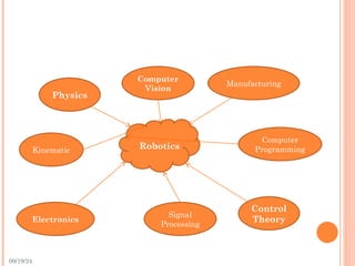
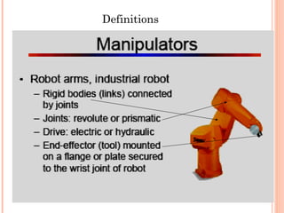
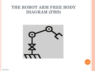
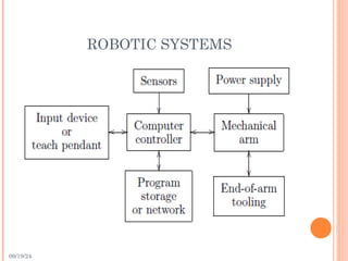
ROBOTICS
‫الرحيم‬ ‫الرحمن‬ ‫اهلل‬ ‫بسم‬
Lecture 2
Robotic System
09/19/24
LECTURE TOPICS
 Definitions and general concepts.
 Symbolic Representation of Robots.
 Robotic Systems.
 Classification of Robotic Manipulators.
09/19/24
ROBOT
 The term robot was first introduced into our
vocabulary by the Czech playwright Karel Capek
in 1920.
 The word robota being the Czech word for work.
09/19/24
ROBOTICS
 Robotics is a relatively young field of modern
technology that crosses traditional engineering
boundaries.
 Understanding the complexity of robots and their
applications requires knowledge of electrical
engineering, mechanical engineering, systems and
industrial engineering, computer science,
economics, and mathematics.
 New disciplines of engineering, such as
manufacturing engineering, applications
engineering, and knowledge engineering have
emerged to deal with the complexity of the field of
robotics and factory automation.
09/19/24
Robotics
Manufacturing
Computer
Vision
Physics
Computer
Programming
Control
Theory
Signal
Processing
Electronics
Kinematic
09/19/24
ROBOT DEFINITION
 An official definition of a robot comes from the
Robot Institute of America (RIA):
“ A robot is a reprogrammable multifunctional
manipulator designed to move material, parts,
tools, or specialized devices through variable
programmed motions for the performance of a
variety of tasks” .
09/19/24
7
ROBOT APPLICATIONS
 Robots are used when the task is difficult
manually, or dangerous, such as:
 welding, painting industries.
 electronics assembly.
 underwater and space exploration.
 hazardous applications in government labs,
nuclear facilities, and medical labs.
09/19/24
SYMBOLIC REPRESENTATION OF
ROBOTS
 Robot Manipulators are composed of links
connected by joints to form a kinematic chain.
 Joints are typically rotary (revolute) or linear
(prismatic).
 A revolute joint is like a hinge and allows relative
rotation between two links.
 A prismatic joint allows a linear relative motion
between two links.
 We denote revolute joints by R and prismatic
joints by P.
09/19/24
SYMBOLIC REPRESENTATION OF
ROBOT JOINTS
09/19/24
 If we have a three-link arm with three revolute
joints is an RRR arm.
 Each joint represents the interconnection
between two links.
12
Definitions
09/19/24
THE ROBOT ARM FREE BODY
DIAGRAM (FBD)
13
09/19/24
DEGREES OF FREEDOM (DOF)
 The degrees of freedom, or DOF, is a very
important term to understand.
 Each degree of freedom is a joint on the arm, a
place where it can bend or rotate or translate.
14
09/19/24
DEGREES-OF-FREEDOM
 An object is said to have n degrees-of-freedom
(DOF) if its configuration can be minimally
specified by n parameters.
 Thus, the number of DOF is equal to the
dimension of the configuration space.
 For a robot manipulator, the number of joints
determines the number DOF.
09/19/24
16
 You can typically identify the number of degrees
of freedom by the number of actuators on the
robot arm. (thus joints)
 when building a robot arm you want as enough
degrees of freedom allowed for your application.
17
4 DOF Robot Arm
18
5 DOF Robot Arm
09/19/24
 a manipulator should typically possess at least
six independent DOF. With fewer than six DOF
the arm cannot reach every point in its work
environment with arbitrary orientation.
 Certain applications such as reaching around or
behind obstacles may require more than six DOF.
 A manipulator having more than six links is
referred to as a kinematically redundant
manipulator.
 The difficulty of controlling a manipulator
increases rapidly with the number of links.
09/19/24
WRISTS AND END-EFFECTORS
 The joints in the kinematic chain between the
arm and end-effector are referred to as the wrist.
09/19/24
THE WORKSPACE
 The workspace of a manipulator is the total
volume swept out by the end-effector as the
manipulator executes all possible motions.
 The workspace is constrained by the geometry of
the manipulator as well as mechanical
constraints on the joints.
09/19/24
ACCURACY AND REPEATABILITY
 The accuracy of a manipulator is a measure of
how close the manipulator can come to a given
point within its workspace.
 Repeatability is a measure of how close a
manipulator can return to a previously taught
point.
09/19/24
ROBOTIC SYSTEMS
09/19/24
CLASSIFICATION OF ROBOTIC
MANIPULATORS
 Robot manipulators can be classified by several
criteria:
 Power source.
 Application area.
 Method of control.
 Geometry.
09/19/24
1-POWER SOURCE
 Typically, robots are either electrically,
hydraulically, or pneumatically powered.
 Hydraulic actuators are unrivaled in their speed
of response and torque producing capability.
Therefore hydraulic robots are used primarily for
lifting heavy loads.
 The drawbacks of hydraulic robots are that they
tend to leak hydraulic fluid, require much more
peripheral equipment (such as pumps, which
require more maintenance), and they are noisy.

09/19/24
1-POWER SOURCE
 Electrical robots driven by DC- or AC-servo
motors are increasingly popular since they are
cheaper, cleaner and quieter.
 Pneumatic robots are inexpensive and simple
but cannot be controlled precisely. As a result,
pneumatic robots are limited in their range of
applications and popularity.
09/19/24
2-APPLICATION AREA
 Robots are often classified by application into
assembly and non-assembly robots.
 Assembly robots tend to be small, electrically
driven and either revolute or SCARA in design.
 The main non-assembly application areas to
date have been in welding, spray painting,
material handling, and machine loading and
unloading.
09/19/24
3-METHOD OF CONTROL
 Robots are classified by control method into:
 Servo robots
 Non-servo robots.
 The earliest robots were non-servo robots. These
robots are essentially open-loop devices.
 Servo robots use closed-loop computer control to
determine their motion.
09/19/24
GEOMETRY
 Most industrial manipulators at the present time
have six or fewer degrees-of-freedom.
 These manipulators are usually classified
kinematically on the basis of the first three joints
of the arm to:
 Articulated (RRR)
 Spherical (RRP)
 SCARA (RRP)
 Cylindrical (RPP)
 Cartesian (PPP).
09/19/24
09/19/24
FURTHER READING
 “Robot Modeling and Control “ , By: Mark
W. Spong, Chapter 1.

Robotics: Lecture 2 Robotic System- General concepts

  • 1.
  • 2.
    09/19/24 LECTURE TOPICS  Definitionsand general concepts.  Symbolic Representation of Robots.  Robotic Systems.  Classification of Robotic Manipulators.
  • 3.
    09/19/24 ROBOT  The termrobot was first introduced into our vocabulary by the Czech playwright Karel Capek in 1920.  The word robota being the Czech word for work.
  • 4.
    09/19/24 ROBOTICS  Robotics isa relatively young field of modern technology that crosses traditional engineering boundaries.  Understanding the complexity of robots and their applications requires knowledge of electrical engineering, mechanical engineering, systems and industrial engineering, computer science, economics, and mathematics.  New disciplines of engineering, such as manufacturing engineering, applications engineering, and knowledge engineering have emerged to deal with the complexity of the field of robotics and factory automation.
  • 5.
  • 6.
    09/19/24 ROBOT DEFINITION  Anofficial definition of a robot comes from the Robot Institute of America (RIA): “ A robot is a reprogrammable multifunctional manipulator designed to move material, parts, tools, or specialized devices through variable programmed motions for the performance of a variety of tasks” .
  • 7.
    09/19/24 7 ROBOT APPLICATIONS  Robotsare used when the task is difficult manually, or dangerous, such as:  welding, painting industries.  electronics assembly.  underwater and space exploration.  hazardous applications in government labs, nuclear facilities, and medical labs.
  • 8.
    09/19/24 SYMBOLIC REPRESENTATION OF ROBOTS Robot Manipulators are composed of links connected by joints to form a kinematic chain.  Joints are typically rotary (revolute) or linear (prismatic).  A revolute joint is like a hinge and allows relative rotation between two links.  A prismatic joint allows a linear relative motion between two links.  We denote revolute joints by R and prismatic joints by P.
  • 9.
  • 10.
    09/19/24  If wehave a three-link arm with three revolute joints is an RRR arm.  Each joint represents the interconnection between two links.
  • 11.
  • 12.
    09/19/24 THE ROBOT ARMFREE BODY DIAGRAM (FBD) 13
  • 13.
    09/19/24 DEGREES OF FREEDOM(DOF)  The degrees of freedom, or DOF, is a very important term to understand.  Each degree of freedom is a joint on the arm, a place where it can bend or rotate or translate. 14
  • 14.
    09/19/24 DEGREES-OF-FREEDOM  An objectis said to have n degrees-of-freedom (DOF) if its configuration can be minimally specified by n parameters.  Thus, the number of DOF is equal to the dimension of the configuration space.  For a robot manipulator, the number of joints determines the number DOF.
  • 15.
    09/19/24 16  You cantypically identify the number of degrees of freedom by the number of actuators on the robot arm. (thus joints)  when building a robot arm you want as enough degrees of freedom allowed for your application.
  • 16.
  • 17.
  • 18.
    09/19/24  a manipulatorshould typically possess at least six independent DOF. With fewer than six DOF the arm cannot reach every point in its work environment with arbitrary orientation.  Certain applications such as reaching around or behind obstacles may require more than six DOF.  A manipulator having more than six links is referred to as a kinematically redundant manipulator.  The difficulty of controlling a manipulator increases rapidly with the number of links.
  • 19.
    09/19/24 WRISTS AND END-EFFECTORS The joints in the kinematic chain between the arm and end-effector are referred to as the wrist.
  • 20.
    09/19/24 THE WORKSPACE  Theworkspace of a manipulator is the total volume swept out by the end-effector as the manipulator executes all possible motions.  The workspace is constrained by the geometry of the manipulator as well as mechanical constraints on the joints.
  • 21.
    09/19/24 ACCURACY AND REPEATABILITY The accuracy of a manipulator is a measure of how close the manipulator can come to a given point within its workspace.  Repeatability is a measure of how close a manipulator can return to a previously taught point.
  • 22.
  • 23.
    09/19/24 CLASSIFICATION OF ROBOTIC MANIPULATORS Robot manipulators can be classified by several criteria:  Power source.  Application area.  Method of control.  Geometry.
  • 24.
    09/19/24 1-POWER SOURCE  Typically,robots are either electrically, hydraulically, or pneumatically powered.  Hydraulic actuators are unrivaled in their speed of response and torque producing capability. Therefore hydraulic robots are used primarily for lifting heavy loads.  The drawbacks of hydraulic robots are that they tend to leak hydraulic fluid, require much more peripheral equipment (such as pumps, which require more maintenance), and they are noisy. 
  • 25.
    09/19/24 1-POWER SOURCE  Electricalrobots driven by DC- or AC-servo motors are increasingly popular since they are cheaper, cleaner and quieter.  Pneumatic robots are inexpensive and simple but cannot be controlled precisely. As a result, pneumatic robots are limited in their range of applications and popularity.
  • 26.
    09/19/24 2-APPLICATION AREA  Robotsare often classified by application into assembly and non-assembly robots.  Assembly robots tend to be small, electrically driven and either revolute or SCARA in design.  The main non-assembly application areas to date have been in welding, spray painting, material handling, and machine loading and unloading.
  • 27.
    09/19/24 3-METHOD OF CONTROL Robots are classified by control method into:  Servo robots  Non-servo robots.  The earliest robots were non-servo robots. These robots are essentially open-loop devices.  Servo robots use closed-loop computer control to determine their motion.
  • 28.
    09/19/24 GEOMETRY  Most industrialmanipulators at the present time have six or fewer degrees-of-freedom.  These manipulators are usually classified kinematically on the basis of the first three joints of the arm to:  Articulated (RRR)  Spherical (RRP)  SCARA (RRP)  Cylindrical (RPP)  Cartesian (PPP).
  • 29.
  • 30.
    09/19/24 FURTHER READING  “RobotModeling and Control “ , By: Mark W. Spong, Chapter 1.

Editor's Notes

  • #27 Selective Compliant Articulated Robot for Assembly