Download to read offline


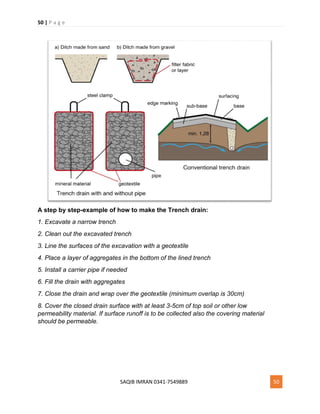
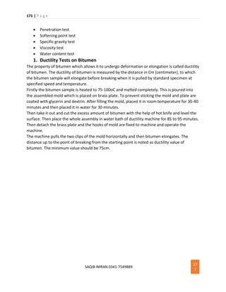
![91 | P a g e
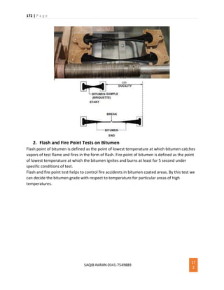
SAQIB IMRAN 0341-7549889 91
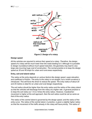
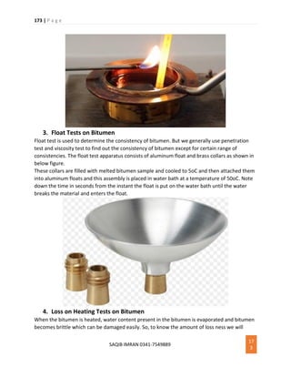
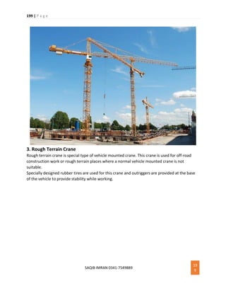
7. Buoyancy Effect
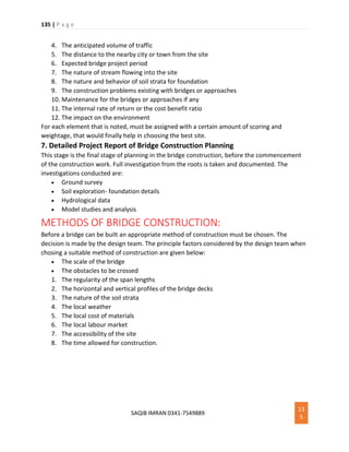
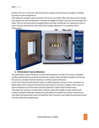
Buoyancy effect is considered for substructures of large bridges submerged under deep water
bodies. Is the depth of submergence is less it can be negligible.
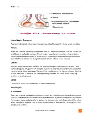
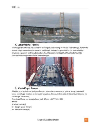
8. Forces by Water Current
When the bridge is to be constructed across a river, some part of the substructure is under
submergence of water. The water current induces horizontal forces on submerged portion. The
forces caused by water currents are maximum at the top of water level and zero at the bottom
water level or at the bed level.
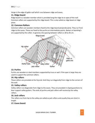
The pressure by water current is P = KW [V2/2g]
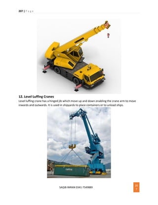
Where P = pressure (kN/m2)
K = constant (value depending upon shape of pier)
W = unit weight of water
V = water current velocity (m/s)
G = acceleration due to gravity (m/s2)
9. Thermal Stresses
Thermal stresses are caused due to temperature. When the temperature is very high or very
low they induce stresses in the bridge elements especially at bearings and deck joints. These
stresses are tensile in nature so, concrete cannot withstand against this and cracks are formed.
To resist this, additional steel reinforcement perpendicular to main reinforcement should be
provided. Expansion joints are also provided.](https://image.slidesharecdn.com/roadbridgerailwayconstructionpdf-180914013513/85/Road-bridge-amp-railway-construction-pdf-91-320.jpg)
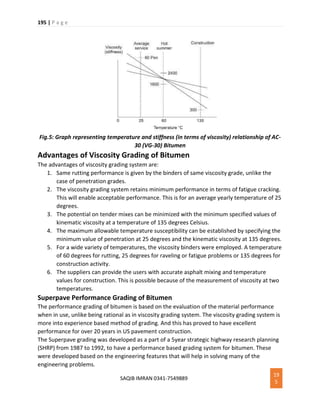


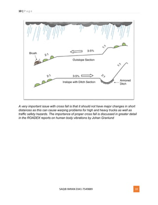
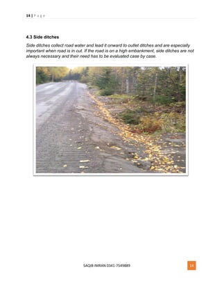
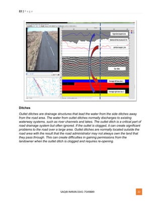
The document is a collection of notes on road and railway construction written by Saqib Imran, a civil engineering student. It contains summaries of the basic steps for constructing a water bound macadam road, including preparation of the subgrade, sub-base, base, wearing course, and shoulders. It also discusses components of road drainage systems such as cross falls, side ditches, and outlet ditches.


![CH_3-Road_Construction_Technology_1658041305[1].ppt](https://cdn.slidesharecdn.com/ss_thumbnails/ch3-roadconstructiontechnology16580413051-231220115938-1b451ea9-thumbnail.jpg?width=640&height=640&fit=bounds)


