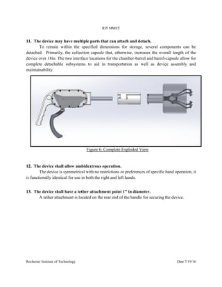
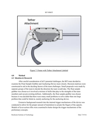
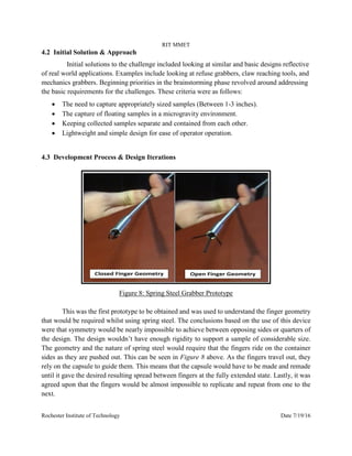
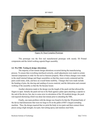
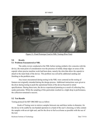
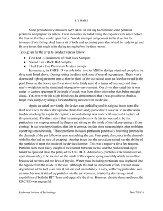
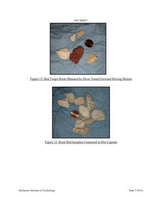
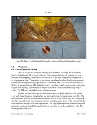
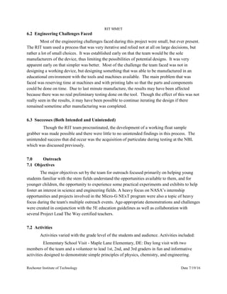
SlideShare a Scribd company logo
1 of 24
Download to read offline
RIT MMET
Rochester Institute of Technology Date 7/19/16
RIT MMET MICRO-G NExT: TABLE OF CONTENTS
1.0 ABSTRACT
2.0 INTRODUCTION
2.1 REPORT STRUCTURE
2.2 CONTENT
3.0 BACKGROUND
3.1 CHALLENGE ADDRESSED
3.2 CHALLENGE PURPOSE
4.0 METHOD
4.1 IDEATION & RESEARCH
4.2 INITIAL SOLUTION & APPROACH
4.3 DEVELOPMENT PROCESS & DESIGN ITERATIONS
4.4 PRE-NBL TESTING & DESIGN ALTERATIONS
5.0 RESULTS
5.1 PROBLEMS ENCOUNTERED AT NBL
5.2 TEST RESULTS
6.0 DISCUSSION
6.1 PROCESS PLANS & DEVIATIONS
6.2 ENGINEERING CHALLENGES FACED
6.3 SUCCESSES (BOTH INTENDED AND UNINTENDED)
7.0 OUTREACH
7.1 OBJECTIVES
7.2 ACTIVITIES
7.3 IMPACT
8.0 CONCLUSION
8.1 LESSONS LEARNED
8.2 SELF DESIGN CRITIQUE
8.3 RECOMMENDATIONS FOR FUTURE DESIGNS
8.4 CONTRIBUTION TO NASA
8.5 REFERENCES
8.6 ACKNOWLEDGEMENTS
RIT MMET
Rochester Institute of Technology Date 7/19/16
1.0 Abstract
The design challenge was comprised of different aspects of real-world factors that
NASA engineers face which were used to test student teams. The Float Sample challenge
revolves around the capture and containment of floating specimens with a range of sizes, finer
details include the need to eliminate contamination and store multiple samples. The Float
Sample Grabber designed by the MMET students of the Rochester Institute of Technology uses
as simple a design as possible without compromising functionality and focuses on adding
elements of reliability and versatility. Solely using mechanical operation, the device, (known as
ORCHID, or Optimized Retrieval and Containment, Hand-Initiated Device), is able to obtain a
minimum of three samples from separate sampling sites. Comprised of commonly used
materials found in tools used on space walks, the ORCHID is designed to operate in both:
chlorinated water, and microgravity environments. The device is made primarily of 3D printed
90% strength, full resolution, ABS as well as Ti-6061 Aircraft Grade Aluminum, and 301
Stainless Steel for the precision interior mechanisms. A strong, clear polycarbonate capsule and
side panels allow for visual confirmation when acquisition of a sample is completed and quick
diagnosis of possible problems. ORCHID was safe to use in the NBL, meeting all the
specifications outlined within the NBL Engineering and Safety Requirements. The device
completed all of the testing goals created by the team to determine the full range of utility. Some
of these tests included capture of float samples, capture of multiple samples at once, capture of
gravel, and capture of fine sand. Secondary testing included user feedback from the diver as well
as durability testing with special instructions to the operator to “be rough” with the device.
Testing data resulted in completion of each task and valuable information relating to user
interaction and design considerations such as better weight distribution and confinement of all
moving parts to prevent contamination and jamming due to small particulate. Outreach efforts
were a major focus of the team throughout the proposal and fabrication periods and further
efforts are being made to expand the NASA Micro-G NExT student participation at RIT through
groups and seminars led by the members of the project ORCHID team. As a final note, the RIT
team succeeded in establishing a working device far exceeding the expectations of the team and
allowing the Rochester Institute of Technology to make its contribution to NASA and to Space
Exploration.
RIT MMET
Rochester Institute of Technology Date 7/19/16
2.0 Introduction
2.1 Report Structure
Following engineering standards, and in accordance with the AIAA technical
conference, this report is a means of representing the NASA based engineering challenge known
as Micro-g NExT entered by students of the Rochester Institute of Technology’s MMET
Department and is outlined with a background into the chosen design challenge along with the
design process, test administration, and results of that challenge. Another key highlight of this
project consisted of outreach made by the RIT team to spread word about NASA JSC
Educational programs. Thus, the report shall manage to cover and discuss both the engineering
facet and any educational outreach simultaneously. All references will be cited in a basic
engineering standardized format.
2.2 Content
Topics discussed throughout this report will include: 1) The chosen challenge and
proposed solution with detailed highlights into the design process. 2) A background into why the
challenge was chosen and how an initial concept and design were brought to fruition. 3) The
results of any testing that was completed both prior to testing in Johnson Space Center’s Neutral
Buoyancy Lab and Post-Testing. 4) An analysis of the tests in relation to possible
improvements, and any successes or failures that may have occurred. 5) A description of
Outreach and its impact. 6) Conclusions will be drawn.
3.0 Background
3.1 Challenged Addressed
Out of the five options to choose from, the design challenge chosen by the RIT team
was the Float Sample Grabber.
3.2 Challenge Purpose
The purpose of the float sample grabber challenge was ideate, conceptualize, design,
manufacture, and test a tool that is able to collect float rock samples in a microgravity
environment. The requirements of this challenge and how the ORCHID fulfills them are as
follow:
RIT MMET
Rochester Institute of Technology Date 7/19/16
1. The device (all parts) shall fit within an 8in x 8in x 18in volume
Dimensioning of the rigid portions of the device were constrained by the maximum volume
requirements. The device has a removable capsule and barrel to maintain the 18in max length.
When the device is in an operational state the overall length is greater than 18 inches, but in its
shipping state, the previously mentioned components will fit in the dead space not taken up by the
main chamber assembly itself to maintain the volume constraints.
Figure 1: Exploded View with Dimensions
2. The device (all parts) shall have a dry weight less than 15 lbs.
Considerations have been made during the design process to limit the material of the
device. A simplistic approach was used to limit unnecessary components. Accompanying this,
the large structural portions of each subassembly are to be constructed from Acrylic and ABS,
keeping only the high strength components that yield stronger forces made of stainless steel.
RIT MMET
Rochester Institute of Technology Date 7/19/16
Figure 2: Exploded View with labels
3. The device shall be compatible with a chlorine water environment
Material selection was influenced by the device’s operation in both microgravity and
chlorine water environments. Research on commonly used materials for spacewalk tools (i.e. the
Pistol-Grip Tool developed by Swales Aerospace) led to the decision to use a durable ABS and
Acrylic make-up, in conjunction with stainless steel. Materials selected are commonly used in
EVA applications. (See figure pictured above for material callout)
4. The device shall capture and contain at least one (1) float rock per sample site
The device is designed to capture one (1) sample from each of the test sites. Possible
additions of more capsules can increase the acquisition amount. The ease of accessibility to
multiple capsules, along with the interfacing method used with the rest of the sample grabbing
assembly allows for ease in operator handling as well as accessibility to multiple float rock
containments.
5. The device shall provide for collection of samples from three (3) separate sites without
cross contamination between sites.
The device is capable of filling three on-board canisters with samples. Once collected the
canisters are sealed and are placed in a collection bag, preventing cross contamination between
sites. The amount of samples able to be collected is purely limited to the amount of additional
capsules that may be carried at one single time.
RIT MMET
Rochester Institute of Technology Date 7/19/16
6. The device shall provide storage of the samples independent of one another in order to
prevent cross contamination during transportation.
The separate capsules that the device utilizes act as the primary containment unit for the
device. They are capable of being sealed after sample collection and removed to be placed within
a sealed bag, preventing contamination during transportation, while maintaining independent
storage.
7. The device shall enable visual verification that a sample has been obtained.
The acquisition capsule will be primarily manufactured out of clear acrylic plastic so that
visual verification can be done simply be observing the container during the capturing
procedure/process.
8. The device shall be capable of obtaining a sample between 1 and 3 inch diameter.
The device was designed around this consideration. The spread of the acquisition fingers
is just over three (3) inches (ID), and closes with a spread under one (1) inch (ID). This action
allows the device to obtain any sample between these specifications. (Including irregular
geometries).
Figure 3: Capsule Positions
9. The capturing task shall be accomplished via one-handed operation.
The action of acquiring the specimen is completely operated via the pull of a trigger using
one extended hand. The reload and reset of the device is a two handed operation. A tether hook-
up location is also featured on the top of the device such that operator functionality may be
completely accessible as shown below (i.e the device will not be dropped once the trigger is
depressed and the operator will still be able to control the function of the sample grabbing device)
RIT MMET
Rochester Institute of Technology Date 7/19/16
Figure 4: Device Frame/Chamber
10. The device shall use only manual power.
Simple machines and mechanical fixtures are used to conduct operation without the use of
non-manual power. Basic linkage and fulcrum functions as well as spring systems are implemented
into the design of the device, allowing all of the power generated by the operator to be further
transmitted to the fingers of the device for sample acquisition.
Figure 5: Exploded View with Linkage Systems Labeled
RIT MMET
Rochester Institute of Technology Date 7/19/16
11. The device may have multiple parts that can attach and detach.
To remain within the specified dimensions for storage, several components can be
detached. Primarily, the collection capsule that, otherwise, increases the overall length of the
device over 18in. The two interface locations for the chamber-barrel and barrel-capsule allow for
complete detachable subsystems to aid in transportation as well as device assembly and
maintainability.
Figure 6: Complete Exploded View
12. The device shall allow ambidextrous operation.
The device is symmetrical with no restrictions or preferences of specific hand operation, it
is functionally identical for use in both the right and left hands.
13. The device shall have a tether attachment point 1” in diameter.
A tether attachment is located on the rear end of the handle for securing the device.
RIT MMET
Rochester Institute of Technology Date 7/19/16
Figure 7: Frame with Tether Attachment Labeled
4.0 Method
4.1 Ideation & Research
After careful consideration of all 5 potential challenges, the RIT team decided to
examine the Float Sample Grabber and Anchoring Device more closely. Decision matrixes were
constructed to aid in the deciding factors of the team challenges. Small proposals were made by
separate groups of the team to decide the direction the team would take. The float sample
grabber was chosen as it involved a mixture of skills that play to the strengths of the team
members and our pre-existing skillsets. Additionally, the float sample grabber was chosen
because it was decided that there were many small problems to solve rather than one large
problem that could be failed at, mainly anchoring for the anchoring device.
Extensive background research into the internal trigger mechanisms of the device was
conducted to allow for the proper amount of translation to actuate the fingers of the capsule.
Models of lever-action rifles were examined to better design the trigger mechanisms of the
preliminary concepts.
RIT MMET
Rochester Institute of Technology Date 7/19/16
4.2 Initial Solution & Approach
Initial solutions to the challenge included looking at similar and basic designs reflective
of real world applications. Examples include looking at refuse grabbers, claw reaching tools, and
mechanics grabbers. Beginning priorities in the brainstorming phase revolved around addressing
the basic requirements for the challenges. These criteria were as follows:
 The need to capture appropriately sized samples (Between 1-3 inches).
 The capture of floating samples in a microgravity environment.
 Keeping collected samples separate and contained from each other.
 Lightweight and simple design for ease of operator operation.
4.3 Development Process & Design Iterations
Figure 8: Spring Steel Grabber Prototype
This was the first prototype to be obtained and was used to understand the finger geometry
that would be required whilst using spring steel. The conclusions based on the use of this device
were that symmetry would be nearly impossible to achieve between opposing sides or quarters of
the design. The design wouldn’t have enough rigidity to support a sample of considerable size.
The geometry and the nature of spring steel would require that the fingers ride on the container
sides as they are pushed out. This can be seen in Figure 8 above. As the fingers travel out, they
rely on the capsule to guide them. This means that the capsule would have to be made and remade
until it gave the desired resulting spread between fingers at the fully extended state. Lastly, it was
agreed upon that the fingers would be almost impossible to replicate and repeat from one to the
next.
RIT MMET
Rochester Institute of Technology Date 7/19/16
The process for making spring steel involves cutting fingers to desired width, bending them
beyond their required contouring, (due to the effects of springback), and then introducing them
into a forge above the transition temperature so as to alleviate stresses that were created through
the bending process of the steel. This process overall would be a challenge that is somewhat
beyond the capability of the RIT Team due to lack of facility equipment and time.
Figure 9: Lego Grabber Prototype
As a result of throwing out the initial spring steel finger design due to complexity in
manufacturing, a new prototype was assembled that is less simple in design, but easier to
manufacture. This prototype is based off of a Lego Crane Design above in Figure 9 that uses rigid
shovel like fingers that are symmetric upon closing and can fit into the capsule container that had
previously been designed. This new prototype is allowed to travel linear and then open, and it is
this functional ability that is being incorporated into the new and final design, seen above in the
Hardware Design section.
RIT MMET
Rochester Institute of Technology Date 7/19/16
Figure 10: Near Complete Prototype
This prototype was the first real manufactured prototype with mostly 3D Printed
components and the initial working capsule/finger assembly.
4.4 Pre-NBL Testing & design Alterations
The majority of last minute design alterations occurred during the manufacturing
process. To ensure that everything interfaced correctly, small adjustments were made to certain
internal components in order for the tool to function properly. Most of these changes were made
to the small internal linkage and finger assemblies so that they more evenly contacted and the
parts could rotate, slide, and have an overall better mobility. Changes that were made include
the bending of pins, the shaving and sanding of excess material, and the lubrication and constant
working of the assembly so that the fits became looser.
Another alteration made to the design was the length of the push rod that allowed the
fingers to open. Initially the push rod was to be flush against a plate upon attaching a capsule to
the end of the device, but, due to some error in calculation of the 3D modeled design, the push
rod required shortening which was done last minute prior to attending the NBL.
Finally, one main problem with the design was found to be that the 3D printed body of
the device had dimensions that were too large to fit on the pallet of RIT’s largest extruding
machine. Thus, the design required that we print the body in two parts and then connect those
pieces using a high strength, two-part, fast-setting epoxy and stainless steel bolts.
RIT MMET
Rochester Institute of Technology Date 7/19/16
Figure 11: Final Prototype Used in NBL Testing (Post-Test)
5.0 Results
5.1 Problems Encountered at NBL
The safety review conducted at the NBL before testing yielded a few concerns with the
device, the main point of consideration was the presence of mildly sharp edges on areas of the
capsule where precise machine work had been done, namely the slots that allow the capsule to
attach to the main body of the device. This problem was solved by additional sanding and
finishing to the problem areas.
Any issues encountered during testing in the NBL were centered on the testing of
features not originally intended during the design process. Additional instructions were given to
the diver during testing to push the operational limits of the device beyond its initial
specifications. During these tests, the device experienced jamming as a result of collecting fine,
sandy particulate. While the sampling of this particulate resulted in a slight drop in performance,
the collection remained a success.
5.2 Test Results
Testing protocol for RIT ORCHID was as follow:
Goals of Testing were to retrieve samples between one and three inches in diameter, for
the device to be usable by one-handed operation in a hand of the user’s choosing, to fully contain
the samples with an air tight seal, and for the diver to feel as at home as possible with the use of
the tool.
RIT MMET
Rochester Institute of Technology Date 7/19/16
Some precautionary measures were taken on test day to eliminate some potential
problems and prepare for others. These measures included filling the capsules with water before
the dive so that they would open freely. Provide multiple components to the diver for the
instance of one failing. And have a kit of tools and secondary parts that would be ready to go and
fix any issues that might arise during testing before the time ran out.
Tests given for the diver to conduct were as follow:
● First Test - Containment of Float Rock Samples
● Second Test - Rock Bed Samples
● Third Test - Fine Particulate Mixture Sample
In summary, the ORCHID was able to be used to fulfill its design intent and complete the
three tests listed above. During testing the diver took note of several occurrences. There was a
downward righting moment arm so that the front of the tool would want to face downward in the
pool, however the device itself was stated to be fairly neutral in terms of buoyancy and thus
nearly weightless in the simulated microgravity environment. Our diver also stated that it was
easier to capture specimen if the angle of attack was from either side rather than being straight
ahead. Yet, even with this slight blind spot, he demonstrated that it was possible to obtain a
target rock sample by using a forward driving motion with the device.
Again, as stated previously, the device was pushed beyond its original intent upon the
third test where the diver attempted to obtain fine sandy particulate. However, even after some
trouble attaching the cap to the capsule a second attempt was made with successful capture of
this particulate. The diver stated that the main problems with this test seemed to be that
particulate was seeping around the fingers and sitting on the inside of the lid, preventing it from
closing. It has been hypothesized that this is correct, but that there were multiple other problems
occurring simultaneously. These problems included particulate potentially becoming jammed in
the channels of the pin followers upon reattaching the cap. Finer particulate, once in the channels
with the pins had no way of escaping. Another issue that the particulate raised was the ability of
the particles to enter the inside of the device chamber. This was a negative for a few reasons.
Particles were most likely caught in the channel between the rail and the push rod making it
harder to open and close the petals of the ORCHID. Additionally, particles were found later on
upon disassembly to be located on the inside of the capsule spring assembly which means that
because of currents and the laws of physics. Water mass including particulate was displaced into
the capsule from the inside of the tool. Although this had no immediate effect, it would cause
degradation of the tool over time if not serviced immediately. Lastly, collecting particulate was
an issue because it kicked up particles into the environment, drastically decreasing visual
capabilities of both the RIT Team and especially the diver. However, despite these problems, the
ORCHID was successful.
RIT MMET
Rochester Institute of Technology Date 7/19/16
Figure 12: Red Target Rock Obtained by Diver Tested Forward Driving Motion
Figure 13: Rock Bed Samples Contained in One Capsule
RIT MMET
Rochester Institute of Technology Date 7/19/16
Figure 14: Bag of Fine Particulate Obtained by Success of Second Attempt to Acquire
6.0 Discussion
6.1 Process Plans & Deviations
Most of the process was dealt with in a crunch of time. Although this was not the
team’s original intent, this is how it ended up. The conceptualization and proposal ran very
smoothly, but the Spring Semester was not conducive to the team being able to complete all of
its milestones on time. This resulted in last minute manufacturing of the final device prototype
with minimal to no pre-testing or pre-test data to provide NASA or to be used as a reference at
NASA. It was stated in the TRR Safety Review by one of the NASA engineers that engineering
is equal parts building a product and having the calculation and evidence to back up why it
works. The RIT team was lacking in the latter department.
Beyond the plans of design and manufacture, the NBL plans specifically for testing
went well. Since the device was complete and a protocol setup, testing ran quite smoothly. The
only deviations from the initial protocol were done after all of the desired tests were completed
and there was still ample time remaining for more testing to occur. It was in this instance that the
team decided to attempt collection of particulate. It’s very important to note that collecting finer
particulate was never intended originally, but was only done to test the capabilities of the float
sample grabber ORCHID.
RIT MMET
Rochester Institute of Technology Date 7/19/16
6.2 Engineering Challenges Faced
Most of the engineering challenges faced during this project were small, but ever present.
The RIT team used a process that was very iterative and relied not at all on large decisions, but
rather a lot of small choices. It was established early on that the team would be the sole
manufacturers of the device, thus limiting the possibilities of potential designs. It was very
apparent early on that simpler was better. Most of the challenge the team faced was not in
designing a working device, but designing something that was able to be manufactured in an
educational environment with the tools and machines available. The main problem that was
faced was reserving time at machines and with printing labs so that the parts and components
could be done on time. Due to last minute manufacture, the results may have been affected
because there was no real preliminary testing done on the tool. Though the effect of this was not
really seen in the results, it may have been possible to continue iterating the design if there
remained sometime after manufacturing was completed.
6.3 Successes (Both Intended and Unintended)
Though the RIT team procrastinated, the development of a working float sample
grabber was made possible and there were little to no unintended findings in this process. The
unintended success that did occur was the acquisition of particulate during testing at the NBL
which was discussed previously.
7.0 Outreach
7.1 Objectives
The major objectives set by the team for outreach focused primarily on helping young
students familiar with the stem fields understand the opportunities available to them, and for
younger children, the opportunity to experience some practical experiments and exhibits to help
foster an interest in science and engineering fields. A heavy focus on NASA’s internship
opportunities and projects involved in the Micro-G NExT program were also a topic of heavy
focus during the team's multiple outreach events. Age-appropriate demonstrations and challenges
were created in conjunction with the 5E education guidelines as well as collaboration with
several Project Lead The Way certified teachers.
7.2 Activities
Activities varied with the grade level of the students and audience. Activities included:
Elementary School Visit - Maple Lane Elementary, DE: Day long visit with two
members of the team and a volunteer to lead 1st, 2nd, and 3rd graders in fun and informative
activities designed to demonstrate simple principles of physics, chemistry, and engineering.
RIT MMET
Rochester Institute of Technology Date 7/19/16
Middle School Visit - DeWitt Middle School, Ithaca, NY: Gave presentation on project
ORCHID to a few tech ed. classes and presented students with an engineering activity that
involved creating a paper structure strong enough to protect five small cherry tomatoes from a
falling wooden hammer. Students were awarded points based on how many tomatoes survived in
the target area.
High School Visit - Ithaca High School, NY: Gave presentation on project ORCHID to
several tech ed. classes at Ithaca High to classes of 9th, 10th, and 11th grade students. Students
were also given a short “statics” based challenge allowing them to experience constraints of
limited materials and time.
High School Visit - 12 Corners High School, Rochester, NY: Gave presentation on
project ORCHID to one tech ed. class consisting of mixed age high school students. The same
engineering activity given to Middle School students was tested here as well with some stricter
rules.
Imagine RIT - Day long Educational Festival located at RIT where the team exhibited
the design process of ORCHID, the prototypes built so far at that time, and a small activity
where onlookers could test the device on picking up golf balls, lacrosse balls, and baseballs
successfully. The device and the design process was explained to all who inquired and a poster
was setup to inform people about the project. This event helped the team to become more
comfortable explaining the device to other people.
7.3 Impact
Figure 15: Physics Activity at Maple Lane Elementary in Delaware
RIT MMET
Rochester Institute of Technology Date 7/19/16
Figure 16: Imagine RIT Exhibit Describing the device and Purpose of Project to Public
Figure 17: Additional Chemistry, STEM Related Experiment with Elementary School Students
RIT MMET
Rochester Institute of Technology Date 7/19/16
8.0 Conclusion
8.1 Lessons Learned
The design process was found to be very challenging. For the RIT team this was
caused by the clashing of ideas between members of the group. With so many different ideas
flowing sometimes it's a challenge to filter through and find the best ones. This was done by the
RIT team in an open debate type form where people were always able to offer their ideas or
knowledge on a subject and the team would attempt to vote on what they thought. This was
found to be the most democratic way to manage technical issues.
Upon traveling to NASA it was learned that the items required from the team for this
project to succeed were directly related to the material learned in class. It was also learned that
the engineers at NASA think similarly to the engineers anywhere else. They are engineers,
regardless of where they work and thus it was easy to find common ground in both ideating and
design.
As a team, trust was a major issue. Trusting each other with tasks was a challenging
thing to overcome, but it seemed to prove an obtainable feat. This and time management in
order to coordinate scheduled time for meeting were the main lessons learned by the team.
8.2 Self Design Critique
A major critique the team and others have offered is the weight of the tool. ORCHID is
significantly over-engineered. In terms of material availability, there is too much. It is not
necessarily in one feature of the device opposed to another, but rather as a whole the device is a
bit bulkier than it needs to be. By removing excess material the tool would become a smaller,
lighter weight, more manageable in a gravitational environment. It would also look sleeker in its
appeal and therefore be more ergonomic in its approach. NASA designed instruments always
seem to hold some of this aesthetic, a sort of futuristic and bold approach to tools and hardware.
Removing material in this way would have potentially avoided the fact that the
ORCHID had a downward righting moment. To combat this, some low density foam could be
placed in areas where material had been excavated thus maintaining the same or similar look, but
allowing for better practice in a simulated microgravity environment.
Another possibility for improving performance would be to eliminate open drain ways
to the internal chamber and mechanisms of the device. By doing this, no particulate would be
able to enter and interfere with componentry such as what occurred during testing at the NBL.
Originally, the design was intended to allow the chamber to fill with water immediately upon
submergence so as to avoid the buildup of pressure between the air inside and the liquid
environment outside as well as to create a more neutrally buoyant tool. However, with some
reconsideration, it seems that the chamber would be able to fill itself without the use of
secondary entrance holes and channels.
RIT MMET
Rochester Institute of Technology Date 7/19/16
A last minute edition to the tool were lines to show the diver how to attach the cap to
the capsule upon collection of samples. However, this technique could have been done better so
that the line would show where to line the cap up rather than where the line should be in its
completely closed state. These two things are relatively similar in proximity, but led to some
confusion for the diver. Thus it would be better to change their position in the future and
perhaps add lines to the device chamber so as to ease the connection of the capsule to the
chamber as well. Additionally, it was mentioned by a NASA engineer that some text could be
applied to the cap to indicate the direction for either open or close. This may be a good idea,
though it should be noted that this may not be necessary as once the user acquaints
himself/herself with the ORCHID it becomes very easy to operate and to remember/achieve the
orientations necessary for attachment and detachment of capsules and their respective caps.
Lastly, a change could be made to the finger assembly so that the petals extend farther
up each of the fingers, avoiding the instance of samples protruding or passing through the
openings between fingers. This purpose could also be obtained by passing some type of webbing
or mesh between the fingers to act as a net and to secure that no particles and/or samples can
penetrate to unwanted areas inside of the capsule. Doing this would eliminate samples being
caught in the cap as well as samples being caught under the linkages of the finger assembly and
between the finger-back and the inside wall of the capsule. Therefore, closing of capsules after
sample acquisition would almost never fail no matter the size of the particulate desired.
8.3 Recommendations For Future Designs
It would be significant if the next iteration of this design were to consist of
interchangeable capsules with differing purposes. One to chip samples, one to collect, one to
anchor, one to core, all contained in a single device. During the trip to JSC it was shown that
this type of engineering project is already in development, but it could be taken to the next level.
The next iteration should be a device that can be altered on the space station, repaired on the
space station and ultimately be the only necessary tool for scientific field research and
exploration of planetary sampling.
The next iteration is one where engineering and manufacturing combine to allow for 3D
printing to occur on the ISS and other craft so that parts can be made right there when something
breaks, and plastics could be recycled into the machine for a nearly endless supply of available
material. New part files could be sent to the station to make upgrades to equipment such as this.
8.4 Contribution To NASA
Overall, this project allowed ideas to be spread and hopefully increase the size of the
idea generation pool that NASA currently sits on. It is imperative that we reach mars in the next
decade, thus even the smallest project can have a large impact on a mission of this caliber.
RIT MMET
Rochester Institute of Technology Date 7/19/16
8.5 References
Backes, Paul, Wayne Zimmerman, Jack Jones, and Caleb Gritters. "Harpoon-based Sampling for
Planetary Applications." 2008 IEEE Aerospace Conference (2008): n. pag. Web.
Delombard, Richard, Allen Karchmer, Glenn Bushnell, Donald Edberg, and Bjarni Tryggvason.
"Microgravity Environment Countermeasures - Panel Discussion." 35th Aerospace Sciences
Meeting and Exhibit (1997): n. pag. Web.
Dunbar, Brian. "Innovative Tools for an Out-of-This-World Job." NASA. NASA, 09 May 2008.
Web. 28 Oct. 2015.
Expedia. "Now Is a Great Time to Join Expedia+ Rewards!" Expedia Travel: Vacations, Cheap
Flights, Airline Tickets & Airfares. Expedia, 2015. Web. 28 Oct. 2015.
"Formative vs Summative Assessment." - Enhancing Education. N.p., n.d. Web. 28 Oct. 2015.
Lekan, Jack. "Microgravity Research in NASA Ground-based Facilities." 27th Aerospace
Sciences Meeting (1989): n. pag. Web.
Levine, Stephen, and Michael Snyder. "Microgravity Cube Lab Experiment Design: Setting New
Precedents for Micro-Gravity Testing." AIAA SPACE 2012 Conference & Exposition (2012): n.
pag. Web.
"Lexan." - Materials Engineering. N.p., n.d. Web. 28 Oct. 2015.
Matweb LLC. "Aluminum 6061-T6; 6061-T651." MatWeb - The Online Materials Information
Resource. Matweb LLC, 2015. Web. 28 Oct. 2015.
McMASTER-CARR. "Material Cost." McMaster-Carr. N.p., 2015. Web. 28 Oct. 2015.
"NASA - Reduced Gravity Student Flight Opportunities Program." N.p., n.d. Web. 28 Oct. 2015.
SABIC. "LEXAN ™ Resin 101 Datasheet." SABIC's Innovative Plastics LEXAN PC. Saudi
Basic Industries Corporation, 2015. Web. 28 Oct. 2015.
RIT MMET
Rochester Institute of Technology Date 7/19/16
8.6 Acknowledgments
NYS NASA Space Grant Consortium (Through Cornell University, Correspondent Erica H.
Miles) - Contributed funds for travel and housing whilst in Houston
Harris Corporation - Contributed funds for materials
RIT MMET - Contributed their services in the form of usable machinery for the team
RIT Office of the Vice President of Research - Contributed the most monetarily
AIAA Niagara Frontier Section - Monetary contribution
ASME Rochester Section - Monetary contribution
Alan Raisanen Ph.D. - Assisted the team with manufacturing and provided material
Lucas Black (Additional team member) - Assisted in CNC manufacturing
Chandler Daub (Honorary team Member) - Assisted in all 3D printing operations
NASA JSC - Provided us this opportunity and contributed additional funds to all the teams
All of the contributions given to the team had a great impact. In combination they allowed the
RIT team to both create a successful device and then afford to travel to Houston and test that
device. All of the help was greatly appreciated!

More Related Content

What's hot

Non Destructive Testing
Non Destructive TestingNon Destructive Testing
Non Destructive TestingHimanshi Gupta
 
Non-Destructive testing - Report
Non-Destructive testing - ReportNon-Destructive testing - Report
Non-Destructive testing - ReportSarchia Khursheed
 
Introduction to non destructive testing (ndt)
Introduction to non destructive testing (ndt)Introduction to non destructive testing (ndt)
Introduction to non destructive testing (ndt)Mohamed Karim Hassanin
 
د حاتم البيطار استشاري وجراح الفم والاسنان 01005684344 اتصل للحجز بالعيادة D...
د حاتم البيطار استشاري وجراح الفم والاسنان 01005684344 اتصل للحجز بالعيادة  D...د حاتم البيطار استشاري وجراح الفم والاسنان 01005684344 اتصل للحجز بالعيادة  D...
د حاتم البيطار استشاري وجراح الفم والاسنان 01005684344 اتصل للحجز بالعيادة D...د حاتم البيطار
 
Surface NDT methods
Surface NDT methodsSurface NDT methods
Surface NDT methodsmahe49
 
Non destructive testing (ndt)
Non destructive testing (ndt)Non destructive testing (ndt)
Non destructive testing (ndt)Lahiru Dilshan
 

What's hot (8)

20141213_04_FoinTR_AOP201507_v3
20141213_04_FoinTR_AOP201507_v320141213_04_FoinTR_AOP201507_v3
20141213_04_FoinTR_AOP201507_v3
 
Non Destructive Testing
Non Destructive TestingNon Destructive Testing
Non Destructive Testing
 
Non-Destructive testing - Report
Non-Destructive testing - ReportNon-Destructive testing - Report
Non-Destructive testing - Report
 
Introduction to non destructive testing (ndt)
Introduction to non destructive testing (ndt)Introduction to non destructive testing (ndt)
Introduction to non destructive testing (ndt)
 
د حاتم البيطار استشاري وجراح الفم والاسنان 01005684344 اتصل للحجز بالعيادة D...
د حاتم البيطار استشاري وجراح الفم والاسنان 01005684344 اتصل للحجز بالعيادة  D...د حاتم البيطار استشاري وجراح الفم والاسنان 01005684344 اتصل للحجز بالعيادة  D...
د حاتم البيطار استشاري وجراح الفم والاسنان 01005684344 اتصل للحجز بالعيادة D...
 
Surface NDT methods
Surface NDT methodsSurface NDT methods
Surface NDT methods
 
Non destructive testing (ndt)
Non destructive testing (ndt)Non destructive testing (ndt)
Non destructive testing (ndt)
 
NDT
NDTNDT
NDT
 

Viewers also liked

Clipping perú 2021 mes mayo parte20
Clipping perú 2021 mes mayo parte20Clipping perú 2021 mes mayo parte20
Clipping perú 2021 mes mayo parte20Perú 2021
 
WPSS Industrial Structures Mezzanines - Types, Features and Benefits
WPSS Industrial Structures Mezzanines - Types, Features and BenefitsWPSS Industrial Structures Mezzanines - Types, Features and Benefits
WPSS Industrial Structures Mezzanines - Types, Features and Benefitsjacelyn smith
 
Relazione sulla lotta contro la corruzione e il seguito dato alla risoluzione...
Relazione sulla lotta contro la corruzione e il seguito dato alla risoluzione...Relazione sulla lotta contro la corruzione e il seguito dato alla risoluzione...
Relazione sulla lotta contro la corruzione e il seguito dato alla risoluzione...eleonora9380
 
Emagreça com sucesso!
Emagreça com sucesso!Emagreça com sucesso!
Emagreça com sucesso!Shake de Chia
 
Presentacin1 130717181111-phpapp02
Presentacin1 130717181111-phpapp02Presentacin1 130717181111-phpapp02
Presentacin1 130717181111-phpapp02alejo1023
 
TDWI BP Report Emerging Technologies
TDWI BP Report Emerging TechnologiesTDWI BP Report Emerging Technologies
TDWI BP Report Emerging TechnologiesAndrey Karpov
 
Patrick Biddescombe - Using Inbound to Source, Interview and Hire Talent
Patrick Biddescombe - Using Inbound to Source, Interview and Hire TalentPatrick Biddescombe - Using Inbound to Source, Interview and Hire Talent
Patrick Biddescombe - Using Inbound to Source, Interview and Hire TalentINBOUND
 
Lisbeth torres
Lisbeth torresLisbeth torres
Lisbeth torres170499
 

Viewers also liked (13)

Clipping perú 2021 mes mayo parte20
Clipping perú 2021 mes mayo parte20Clipping perú 2021 mes mayo parte20
Clipping perú 2021 mes mayo parte20
 
WPSS Industrial Structures Mezzanines - Types, Features and Benefits
WPSS Industrial Structures Mezzanines - Types, Features and BenefitsWPSS Industrial Structures Mezzanines - Types, Features and Benefits
WPSS Industrial Structures Mezzanines - Types, Features and Benefits
 
Relazione sulla lotta contro la corruzione e il seguito dato alla risoluzione...
Relazione sulla lotta contro la corruzione e il seguito dato alla risoluzione...Relazione sulla lotta contro la corruzione e il seguito dato alla risoluzione...
Relazione sulla lotta contro la corruzione e il seguito dato alla risoluzione...
 
Emagreça com sucesso!
Emagreça com sucesso!Emagreça com sucesso!
Emagreça com sucesso!
 
All About Me
All About MeAll About Me
All About Me
 
Presentacin1 130717181111-phpapp02
Presentacin1 130717181111-phpapp02Presentacin1 130717181111-phpapp02
Presentacin1 130717181111-phpapp02
 
Os Terroristas
Os TerroristasOs Terroristas
Os Terroristas
 
TDWI BP Report Emerging Technologies
TDWI BP Report Emerging TechnologiesTDWI BP Report Emerging Technologies
TDWI BP Report Emerging Technologies
 
3 e uml
3 e uml3 e uml
3 e uml
 
BMW
BMWBMW
BMW
 
Patrick Biddescombe - Using Inbound to Source, Interview and Hire Talent
Patrick Biddescombe - Using Inbound to Source, Interview and Hire TalentPatrick Biddescombe - Using Inbound to Source, Interview and Hire Talent
Patrick Biddescombe - Using Inbound to Source, Interview and Hire Talent
 
Lisbeth torres
Lisbeth torresLisbeth torres
Lisbeth torres
 
Expo.slideshare
Expo.slideshareExpo.slideshare
Expo.slideshare
 

Similar to RIT_MMET_Final_Report

RIT MMET Microgravity NExT Project Proposal
RIT MMET Microgravity NExT Project ProposalRIT MMET Microgravity NExT Project Proposal
RIT MMET Microgravity NExT Project ProposalChristian Pape
 
Fabrication of Pin on Disc Wear Test Rig
Fabrication of Pin on Disc Wear Test RigFabrication of Pin on Disc Wear Test Rig
Fabrication of Pin on Disc Wear Test Rigijtsrd
 
MTU ABET Final
MTU ABET FinalMTU ABET Final
MTU ABET FinalDan Burg
 
Designing Facility Layout and Effective Material Handling for a Ceramic Insul...
Designing Facility Layout and Effective Material Handling for a Ceramic Insul...Designing Facility Layout and Effective Material Handling for a Ceramic Insul...
Designing Facility Layout and Effective Material Handling for a Ceramic Insul...IRJET Journal
 
4 Super Lightweight Tank - Risk Management
4 Super Lightweight Tank - Risk Management4 Super Lightweight Tank - Risk Management
4 Super Lightweight Tank - Risk Managementpmb25
 
Design and Fabrication of Tamarind Seed Removal Machine
Design and Fabrication of Tamarind Seed Removal MachineDesign and Fabrication of Tamarind Seed Removal Machine
Design and Fabrication of Tamarind Seed Removal MachineIRJET Journal
 
Design and Fabrication of Tamarind Seed Removal Machine
Design and Fabrication of Tamarind Seed Removal MachineDesign and Fabrication of Tamarind Seed Removal Machine
Design and Fabrication of Tamarind Seed Removal MachineIRJET Journal
 
SPE-96655-MS (1).pdf
SPE-96655-MS (1).pdfSPE-96655-MS (1).pdf
SPE-96655-MS (1).pdfOmarSAlAbri
 
SPE-96655-MS (1).pdf
SPE-96655-MS (1).pdfSPE-96655-MS (1).pdf
SPE-96655-MS (1).pdfOmarSAlAbri
 
Inspection Systems for Additive Manufacturing
Inspection Systems for Additive ManufacturingInspection Systems for Additive Manufacturing
Inspection Systems for Additive ManufacturingKTN
 
Analysis of tensile behavior hybrid carbon jute fiber reniforced epoxy composite
Analysis of tensile behavior hybrid carbon jute fiber reniforced epoxy compositeAnalysis of tensile behavior hybrid carbon jute fiber reniforced epoxy composite
Analysis of tensile behavior hybrid carbon jute fiber reniforced epoxy compositeIAEME Publication
 
Design & Development of Articulated Inspection ARM for in House Inspection in...
Design & Development of Articulated Inspection ARM for in House Inspection in...Design & Development of Articulated Inspection ARM for in House Inspection in...
Design & Development of Articulated Inspection ARM for in House Inspection in...ijsrd.com
 
An experimental study on factors affecting Cold Extrusion of steels
An experimental study on factors affecting Cold Extrusion of steelsAn experimental study on factors affecting Cold Extrusion of steels
An experimental study on factors affecting Cold Extrusion of steelsIRJET Journal
 
GT2PropulsionSystemSubmissionDocument
GT2PropulsionSystemSubmissionDocumentGT2PropulsionSystemSubmissionDocument
GT2PropulsionSystemSubmissionDocumentDiana Alsindy
 
GT2PropulsionSystemSubmissionDocument
GT2PropulsionSystemSubmissionDocumentGT2PropulsionSystemSubmissionDocument
GT2PropulsionSystemSubmissionDocumentFeennette Navarro
 
IRJET- In-Situ Monitoring for Fatigue Crack Detection using Control System an...
IRJET- In-Situ Monitoring for Fatigue Crack Detection using Control System an...IRJET- In-Situ Monitoring for Fatigue Crack Detection using Control System an...
IRJET- In-Situ Monitoring for Fatigue Crack Detection using Control System an...IRJET Journal
 
Method for cost-effective trans aortic valve replacement device prototyping
Method for cost-effective trans aortic valve replacement device prototypingMethod for cost-effective trans aortic valve replacement device prototyping
Method for cost-effective trans aortic valve replacement device prototypingIJAAS Team
 

Similar to RIT_MMET_Final_Report (20)

RIT MMET Microgravity NExT Project Proposal
RIT MMET Microgravity NExT Project ProposalRIT MMET Microgravity NExT Project Proposal
RIT MMET Microgravity NExT Project Proposal
 
Fabrication of Pin on Disc Wear Test Rig
Fabrication of Pin on Disc Wear Test RigFabrication of Pin on Disc Wear Test Rig
Fabrication of Pin on Disc Wear Test Rig
 
MTU ABET Final
MTU ABET FinalMTU ABET Final
MTU ABET Final
 
Designing Facility Layout and Effective Material Handling for a Ceramic Insul...
Designing Facility Layout and Effective Material Handling for a Ceramic Insul...Designing Facility Layout and Effective Material Handling for a Ceramic Insul...
Designing Facility Layout and Effective Material Handling for a Ceramic Insul...
 
4 Super Lightweight Tank - Risk Management
4 Super Lightweight Tank - Risk Management4 Super Lightweight Tank - Risk Management
4 Super Lightweight Tank - Risk Management
 
Modeling and Analysis of Clamp for Brake Spider Fixture by Fem Using Ansys So...
Modeling and Analysis of Clamp for Brake Spider Fixture by Fem Using Ansys So...Modeling and Analysis of Clamp for Brake Spider Fixture by Fem Using Ansys So...
Modeling and Analysis of Clamp for Brake Spider Fixture by Fem Using Ansys So...
 
Design and Fabrication of Tamarind Seed Removal Machine
Design and Fabrication of Tamarind Seed Removal MachineDesign and Fabrication of Tamarind Seed Removal Machine
Design and Fabrication of Tamarind Seed Removal Machine
 
Design and Fabrication of Tamarind Seed Removal Machine
Design and Fabrication of Tamarind Seed Removal MachineDesign and Fabrication of Tamarind Seed Removal Machine
Design and Fabrication of Tamarind Seed Removal Machine
 
Application of Reverse Engineering and CAD/CAM in Field of Prosthetics-A Make...
Application of Reverse Engineering and CAD/CAM in Field of Prosthetics-A Make...Application of Reverse Engineering and CAD/CAM in Field of Prosthetics-A Make...
Application of Reverse Engineering and CAD/CAM in Field of Prosthetics-A Make...
 
SPE-96655-MS (1).pdf
SPE-96655-MS (1).pdfSPE-96655-MS (1).pdf
SPE-96655-MS (1).pdf
 
SPE-96655-MS (1).pdf
SPE-96655-MS (1).pdfSPE-96655-MS (1).pdf
SPE-96655-MS (1).pdf
 
Inspection Systems for Additive Manufacturing
Inspection Systems for Additive ManufacturingInspection Systems for Additive Manufacturing
Inspection Systems for Additive Manufacturing
 
Analysis of tensile behavior hybrid carbon jute fiber reniforced epoxy composite
Analysis of tensile behavior hybrid carbon jute fiber reniforced epoxy compositeAnalysis of tensile behavior hybrid carbon jute fiber reniforced epoxy composite
Analysis of tensile behavior hybrid carbon jute fiber reniforced epoxy composite
 
Design & Development of Articulated Inspection ARM for in House Inspection in...
Design & Development of Articulated Inspection ARM for in House Inspection in...Design & Development of Articulated Inspection ARM for in House Inspection in...
Design & Development of Articulated Inspection ARM for in House Inspection in...
 
An experimental study on factors affecting Cold Extrusion of steels
An experimental study on factors affecting Cold Extrusion of steelsAn experimental study on factors affecting Cold Extrusion of steels
An experimental study on factors affecting Cold Extrusion of steels
 
GT2PropulsionSystemSubmissionDocument
GT2PropulsionSystemSubmissionDocumentGT2PropulsionSystemSubmissionDocument
GT2PropulsionSystemSubmissionDocument
 
GT2PropulsionSystemSubmissionDocument
GT2PropulsionSystemSubmissionDocumentGT2PropulsionSystemSubmissionDocument
GT2PropulsionSystemSubmissionDocument
 
Clarion2010-11
Clarion2010-11Clarion2010-11
Clarion2010-11
 
IRJET- In-Situ Monitoring for Fatigue Crack Detection using Control System an...
IRJET- In-Situ Monitoring for Fatigue Crack Detection using Control System an...IRJET- In-Situ Monitoring for Fatigue Crack Detection using Control System an...
IRJET- In-Situ Monitoring for Fatigue Crack Detection using Control System an...
 
Method for cost-effective trans aortic valve replacement device prototyping
Method for cost-effective trans aortic valve replacement device prototypingMethod for cost-effective trans aortic valve replacement device prototyping
Method for cost-effective trans aortic valve replacement device prototyping
 

RIT_MMET_Final_Report

  • 1.
  • 2. RIT MMET Rochester Institute of Technology Date 7/19/16 RIT MMET MICRO-G NExT: TABLE OF CONTENTS 1.0 ABSTRACT 2.0 INTRODUCTION 2.1 REPORT STRUCTURE 2.2 CONTENT 3.0 BACKGROUND 3.1 CHALLENGE ADDRESSED 3.2 CHALLENGE PURPOSE 4.0 METHOD 4.1 IDEATION & RESEARCH 4.2 INITIAL SOLUTION & APPROACH 4.3 DEVELOPMENT PROCESS & DESIGN ITERATIONS 4.4 PRE-NBL TESTING & DESIGN ALTERATIONS 5.0 RESULTS 5.1 PROBLEMS ENCOUNTERED AT NBL 5.2 TEST RESULTS 6.0 DISCUSSION 6.1 PROCESS PLANS & DEVIATIONS 6.2 ENGINEERING CHALLENGES FACED 6.3 SUCCESSES (BOTH INTENDED AND UNINTENDED) 7.0 OUTREACH 7.1 OBJECTIVES 7.2 ACTIVITIES 7.3 IMPACT 8.0 CONCLUSION 8.1 LESSONS LEARNED 8.2 SELF DESIGN CRITIQUE 8.3 RECOMMENDATIONS FOR FUTURE DESIGNS 8.4 CONTRIBUTION TO NASA 8.5 REFERENCES 8.6 ACKNOWLEDGEMENTS
  • 3. RIT MMET Rochester Institute of Technology Date 7/19/16 1.0 Abstract The design challenge was comprised of different aspects of real-world factors that NASA engineers face which were used to test student teams. The Float Sample challenge revolves around the capture and containment of floating specimens with a range of sizes, finer details include the need to eliminate contamination and store multiple samples. The Float Sample Grabber designed by the MMET students of the Rochester Institute of Technology uses as simple a design as possible without compromising functionality and focuses on adding elements of reliability and versatility. Solely using mechanical operation, the device, (known as ORCHID, or Optimized Retrieval and Containment, Hand-Initiated Device), is able to obtain a minimum of three samples from separate sampling sites. Comprised of commonly used materials found in tools used on space walks, the ORCHID is designed to operate in both: chlorinated water, and microgravity environments. The device is made primarily of 3D printed 90% strength, full resolution, ABS as well as Ti-6061 Aircraft Grade Aluminum, and 301 Stainless Steel for the precision interior mechanisms. A strong, clear polycarbonate capsule and side panels allow for visual confirmation when acquisition of a sample is completed and quick diagnosis of possible problems. ORCHID was safe to use in the NBL, meeting all the specifications outlined within the NBL Engineering and Safety Requirements. The device completed all of the testing goals created by the team to determine the full range of utility. Some of these tests included capture of float samples, capture of multiple samples at once, capture of gravel, and capture of fine sand. Secondary testing included user feedback from the diver as well as durability testing with special instructions to the operator to “be rough” with the device. Testing data resulted in completion of each task and valuable information relating to user interaction and design considerations such as better weight distribution and confinement of all moving parts to prevent contamination and jamming due to small particulate. Outreach efforts were a major focus of the team throughout the proposal and fabrication periods and further efforts are being made to expand the NASA Micro-G NExT student participation at RIT through groups and seminars led by the members of the project ORCHID team. As a final note, the RIT team succeeded in establishing a working device far exceeding the expectations of the team and allowing the Rochester Institute of Technology to make its contribution to NASA and to Space Exploration.
  • 4. RIT MMET Rochester Institute of Technology Date 7/19/16 2.0 Introduction 2.1 Report Structure Following engineering standards, and in accordance with the AIAA technical conference, this report is a means of representing the NASA based engineering challenge known as Micro-g NExT entered by students of the Rochester Institute of Technology’s MMET Department and is outlined with a background into the chosen design challenge along with the design process, test administration, and results of that challenge. Another key highlight of this project consisted of outreach made by the RIT team to spread word about NASA JSC Educational programs. Thus, the report shall manage to cover and discuss both the engineering facet and any educational outreach simultaneously. All references will be cited in a basic engineering standardized format. 2.2 Content Topics discussed throughout this report will include: 1) The chosen challenge and proposed solution with detailed highlights into the design process. 2) A background into why the challenge was chosen and how an initial concept and design were brought to fruition. 3) The results of any testing that was completed both prior to testing in Johnson Space Center’s Neutral Buoyancy Lab and Post-Testing. 4) An analysis of the tests in relation to possible improvements, and any successes or failures that may have occurred. 5) A description of Outreach and its impact. 6) Conclusions will be drawn. 3.0 Background 3.1 Challenged Addressed Out of the five options to choose from, the design challenge chosen by the RIT team was the Float Sample Grabber. 3.2 Challenge Purpose The purpose of the float sample grabber challenge was ideate, conceptualize, design, manufacture, and test a tool that is able to collect float rock samples in a microgravity environment. The requirements of this challenge and how the ORCHID fulfills them are as follow:
  • 5. RIT MMET Rochester Institute of Technology Date 7/19/16 1. The device (all parts) shall fit within an 8in x 8in x 18in volume Dimensioning of the rigid portions of the device were constrained by the maximum volume requirements. The device has a removable capsule and barrel to maintain the 18in max length. When the device is in an operational state the overall length is greater than 18 inches, but in its shipping state, the previously mentioned components will fit in the dead space not taken up by the main chamber assembly itself to maintain the volume constraints. Figure 1: Exploded View with Dimensions 2. The device (all parts) shall have a dry weight less than 15 lbs. Considerations have been made during the design process to limit the material of the device. A simplistic approach was used to limit unnecessary components. Accompanying this, the large structural portions of each subassembly are to be constructed from Acrylic and ABS, keeping only the high strength components that yield stronger forces made of stainless steel.
  • 6. RIT MMET Rochester Institute of Technology Date 7/19/16 Figure 2: Exploded View with labels 3. The device shall be compatible with a chlorine water environment Material selection was influenced by the device’s operation in both microgravity and chlorine water environments. Research on commonly used materials for spacewalk tools (i.e. the Pistol-Grip Tool developed by Swales Aerospace) led to the decision to use a durable ABS and Acrylic make-up, in conjunction with stainless steel. Materials selected are commonly used in EVA applications. (See figure pictured above for material callout) 4. The device shall capture and contain at least one (1) float rock per sample site The device is designed to capture one (1) sample from each of the test sites. Possible additions of more capsules can increase the acquisition amount. The ease of accessibility to multiple capsules, along with the interfacing method used with the rest of the sample grabbing assembly allows for ease in operator handling as well as accessibility to multiple float rock containments. 5. The device shall provide for collection of samples from three (3) separate sites without cross contamination between sites. The device is capable of filling three on-board canisters with samples. Once collected the canisters are sealed and are placed in a collection bag, preventing cross contamination between sites. The amount of samples able to be collected is purely limited to the amount of additional capsules that may be carried at one single time.
  • 7. RIT MMET Rochester Institute of Technology Date 7/19/16 6. The device shall provide storage of the samples independent of one another in order to prevent cross contamination during transportation. The separate capsules that the device utilizes act as the primary containment unit for the device. They are capable of being sealed after sample collection and removed to be placed within a sealed bag, preventing contamination during transportation, while maintaining independent storage. 7. The device shall enable visual verification that a sample has been obtained. The acquisition capsule will be primarily manufactured out of clear acrylic plastic so that visual verification can be done simply be observing the container during the capturing procedure/process. 8. The device shall be capable of obtaining a sample between 1 and 3 inch diameter. The device was designed around this consideration. The spread of the acquisition fingers is just over three (3) inches (ID), and closes with a spread under one (1) inch (ID). This action allows the device to obtain any sample between these specifications. (Including irregular geometries). Figure 3: Capsule Positions 9. The capturing task shall be accomplished via one-handed operation. The action of acquiring the specimen is completely operated via the pull of a trigger using one extended hand. The reload and reset of the device is a two handed operation. A tether hook- up location is also featured on the top of the device such that operator functionality may be completely accessible as shown below (i.e the device will not be dropped once the trigger is depressed and the operator will still be able to control the function of the sample grabbing device)
  • 8. RIT MMET Rochester Institute of Technology Date 7/19/16 Figure 4: Device Frame/Chamber 10. The device shall use only manual power. Simple machines and mechanical fixtures are used to conduct operation without the use of non-manual power. Basic linkage and fulcrum functions as well as spring systems are implemented into the design of the device, allowing all of the power generated by the operator to be further transmitted to the fingers of the device for sample acquisition. Figure 5: Exploded View with Linkage Systems Labeled
  • 9. RIT MMET Rochester Institute of Technology Date 7/19/16 11. The device may have multiple parts that can attach and detach. To remain within the specified dimensions for storage, several components can be detached. Primarily, the collection capsule that, otherwise, increases the overall length of the device over 18in. The two interface locations for the chamber-barrel and barrel-capsule allow for complete detachable subsystems to aid in transportation as well as device assembly and maintainability. Figure 6: Complete Exploded View 12. The device shall allow ambidextrous operation. The device is symmetrical with no restrictions or preferences of specific hand operation, it is functionally identical for use in both the right and left hands. 13. The device shall have a tether attachment point 1” in diameter. A tether attachment is located on the rear end of the handle for securing the device.
  • 10. RIT MMET Rochester Institute of Technology Date 7/19/16 Figure 7: Frame with Tether Attachment Labeled 4.0 Method 4.1 Ideation & Research After careful consideration of all 5 potential challenges, the RIT team decided to examine the Float Sample Grabber and Anchoring Device more closely. Decision matrixes were constructed to aid in the deciding factors of the team challenges. Small proposals were made by separate groups of the team to decide the direction the team would take. The float sample grabber was chosen as it involved a mixture of skills that play to the strengths of the team members and our pre-existing skillsets. Additionally, the float sample grabber was chosen because it was decided that there were many small problems to solve rather than one large problem that could be failed at, mainly anchoring for the anchoring device. Extensive background research into the internal trigger mechanisms of the device was conducted to allow for the proper amount of translation to actuate the fingers of the capsule. Models of lever-action rifles were examined to better design the trigger mechanisms of the preliminary concepts.
  • 11. RIT MMET Rochester Institute of Technology Date 7/19/16 4.2 Initial Solution & Approach Initial solutions to the challenge included looking at similar and basic designs reflective of real world applications. Examples include looking at refuse grabbers, claw reaching tools, and mechanics grabbers. Beginning priorities in the brainstorming phase revolved around addressing the basic requirements for the challenges. These criteria were as follows:  The need to capture appropriately sized samples (Between 1-3 inches).  The capture of floating samples in a microgravity environment.  Keeping collected samples separate and contained from each other.  Lightweight and simple design for ease of operator operation. 4.3 Development Process & Design Iterations Figure 8: Spring Steel Grabber Prototype This was the first prototype to be obtained and was used to understand the finger geometry that would be required whilst using spring steel. The conclusions based on the use of this device were that symmetry would be nearly impossible to achieve between opposing sides or quarters of the design. The design wouldn’t have enough rigidity to support a sample of considerable size. The geometry and the nature of spring steel would require that the fingers ride on the container sides as they are pushed out. This can be seen in Figure 8 above. As the fingers travel out, they rely on the capsule to guide them. This means that the capsule would have to be made and remade until it gave the desired resulting spread between fingers at the fully extended state. Lastly, it was agreed upon that the fingers would be almost impossible to replicate and repeat from one to the next.
  • 12. RIT MMET Rochester Institute of Technology Date 7/19/16 The process for making spring steel involves cutting fingers to desired width, bending them beyond their required contouring, (due to the effects of springback), and then introducing them into a forge above the transition temperature so as to alleviate stresses that were created through the bending process of the steel. This process overall would be a challenge that is somewhat beyond the capability of the RIT Team due to lack of facility equipment and time. Figure 9: Lego Grabber Prototype As a result of throwing out the initial spring steel finger design due to complexity in manufacturing, a new prototype was assembled that is less simple in design, but easier to manufacture. This prototype is based off of a Lego Crane Design above in Figure 9 that uses rigid shovel like fingers that are symmetric upon closing and can fit into the capsule container that had previously been designed. This new prototype is allowed to travel linear and then open, and it is this functional ability that is being incorporated into the new and final design, seen above in the Hardware Design section.
  • 13. RIT MMET Rochester Institute of Technology Date 7/19/16 Figure 10: Near Complete Prototype This prototype was the first real manufactured prototype with mostly 3D Printed components and the initial working capsule/finger assembly. 4.4 Pre-NBL Testing & design Alterations The majority of last minute design alterations occurred during the manufacturing process. To ensure that everything interfaced correctly, small adjustments were made to certain internal components in order for the tool to function properly. Most of these changes were made to the small internal linkage and finger assemblies so that they more evenly contacted and the parts could rotate, slide, and have an overall better mobility. Changes that were made include the bending of pins, the shaving and sanding of excess material, and the lubrication and constant working of the assembly so that the fits became looser. Another alteration made to the design was the length of the push rod that allowed the fingers to open. Initially the push rod was to be flush against a plate upon attaching a capsule to the end of the device, but, due to some error in calculation of the 3D modeled design, the push rod required shortening which was done last minute prior to attending the NBL. Finally, one main problem with the design was found to be that the 3D printed body of the device had dimensions that were too large to fit on the pallet of RIT’s largest extruding machine. Thus, the design required that we print the body in two parts and then connect those pieces using a high strength, two-part, fast-setting epoxy and stainless steel bolts.
  • 14. RIT MMET Rochester Institute of Technology Date 7/19/16 Figure 11: Final Prototype Used in NBL Testing (Post-Test) 5.0 Results 5.1 Problems Encountered at NBL The safety review conducted at the NBL before testing yielded a few concerns with the device, the main point of consideration was the presence of mildly sharp edges on areas of the capsule where precise machine work had been done, namely the slots that allow the capsule to attach to the main body of the device. This problem was solved by additional sanding and finishing to the problem areas. Any issues encountered during testing in the NBL were centered on the testing of features not originally intended during the design process. Additional instructions were given to the diver during testing to push the operational limits of the device beyond its initial specifications. During these tests, the device experienced jamming as a result of collecting fine, sandy particulate. While the sampling of this particulate resulted in a slight drop in performance, the collection remained a success. 5.2 Test Results Testing protocol for RIT ORCHID was as follow: Goals of Testing were to retrieve samples between one and three inches in diameter, for the device to be usable by one-handed operation in a hand of the user’s choosing, to fully contain the samples with an air tight seal, and for the diver to feel as at home as possible with the use of the tool.
  • 15. RIT MMET Rochester Institute of Technology Date 7/19/16 Some precautionary measures were taken on test day to eliminate some potential problems and prepare for others. These measures included filling the capsules with water before the dive so that they would open freely. Provide multiple components to the diver for the instance of one failing. And have a kit of tools and secondary parts that would be ready to go and fix any issues that might arise during testing before the time ran out. Tests given for the diver to conduct were as follow: ● First Test - Containment of Float Rock Samples ● Second Test - Rock Bed Samples ● Third Test - Fine Particulate Mixture Sample In summary, the ORCHID was able to be used to fulfill its design intent and complete the three tests listed above. During testing the diver took note of several occurrences. There was a downward righting moment arm so that the front of the tool would want to face downward in the pool, however the device itself was stated to be fairly neutral in terms of buoyancy and thus nearly weightless in the simulated microgravity environment. Our diver also stated that it was easier to capture specimen if the angle of attack was from either side rather than being straight ahead. Yet, even with this slight blind spot, he demonstrated that it was possible to obtain a target rock sample by using a forward driving motion with the device. Again, as stated previously, the device was pushed beyond its original intent upon the third test where the diver attempted to obtain fine sandy particulate. However, even after some trouble attaching the cap to the capsule a second attempt was made with successful capture of this particulate. The diver stated that the main problems with this test seemed to be that particulate was seeping around the fingers and sitting on the inside of the lid, preventing it from closing. It has been hypothesized that this is correct, but that there were multiple other problems occurring simultaneously. These problems included particulate potentially becoming jammed in the channels of the pin followers upon reattaching the cap. Finer particulate, once in the channels with the pins had no way of escaping. Another issue that the particulate raised was the ability of the particles to enter the inside of the device chamber. This was a negative for a few reasons. Particles were most likely caught in the channel between the rail and the push rod making it harder to open and close the petals of the ORCHID. Additionally, particles were found later on upon disassembly to be located on the inside of the capsule spring assembly which means that because of currents and the laws of physics. Water mass including particulate was displaced into the capsule from the inside of the tool. Although this had no immediate effect, it would cause degradation of the tool over time if not serviced immediately. Lastly, collecting particulate was an issue because it kicked up particles into the environment, drastically decreasing visual capabilities of both the RIT Team and especially the diver. However, despite these problems, the ORCHID was successful.
  • 16. RIT MMET Rochester Institute of Technology Date 7/19/16 Figure 12: Red Target Rock Obtained by Diver Tested Forward Driving Motion Figure 13: Rock Bed Samples Contained in One Capsule
  • 17. RIT MMET Rochester Institute of Technology Date 7/19/16 Figure 14: Bag of Fine Particulate Obtained by Success of Second Attempt to Acquire 6.0 Discussion 6.1 Process Plans & Deviations Most of the process was dealt with in a crunch of time. Although this was not the team’s original intent, this is how it ended up. The conceptualization and proposal ran very smoothly, but the Spring Semester was not conducive to the team being able to complete all of its milestones on time. This resulted in last minute manufacturing of the final device prototype with minimal to no pre-testing or pre-test data to provide NASA or to be used as a reference at NASA. It was stated in the TRR Safety Review by one of the NASA engineers that engineering is equal parts building a product and having the calculation and evidence to back up why it works. The RIT team was lacking in the latter department. Beyond the plans of design and manufacture, the NBL plans specifically for testing went well. Since the device was complete and a protocol setup, testing ran quite smoothly. The only deviations from the initial protocol were done after all of the desired tests were completed and there was still ample time remaining for more testing to occur. It was in this instance that the team decided to attempt collection of particulate. It’s very important to note that collecting finer particulate was never intended originally, but was only done to test the capabilities of the float sample grabber ORCHID.
  • 18. RIT MMET Rochester Institute of Technology Date 7/19/16 6.2 Engineering Challenges Faced Most of the engineering challenges faced during this project were small, but ever present. The RIT team used a process that was very iterative and relied not at all on large decisions, but rather a lot of small choices. It was established early on that the team would be the sole manufacturers of the device, thus limiting the possibilities of potential designs. It was very apparent early on that simpler was better. Most of the challenge the team faced was not in designing a working device, but designing something that was able to be manufactured in an educational environment with the tools and machines available. The main problem that was faced was reserving time at machines and with printing labs so that the parts and components could be done on time. Due to last minute manufacture, the results may have been affected because there was no real preliminary testing done on the tool. Though the effect of this was not really seen in the results, it may have been possible to continue iterating the design if there remained sometime after manufacturing was completed. 6.3 Successes (Both Intended and Unintended) Though the RIT team procrastinated, the development of a working float sample grabber was made possible and there were little to no unintended findings in this process. The unintended success that did occur was the acquisition of particulate during testing at the NBL which was discussed previously. 7.0 Outreach 7.1 Objectives The major objectives set by the team for outreach focused primarily on helping young students familiar with the stem fields understand the opportunities available to them, and for younger children, the opportunity to experience some practical experiments and exhibits to help foster an interest in science and engineering fields. A heavy focus on NASA’s internship opportunities and projects involved in the Micro-G NExT program were also a topic of heavy focus during the team's multiple outreach events. Age-appropriate demonstrations and challenges were created in conjunction with the 5E education guidelines as well as collaboration with several Project Lead The Way certified teachers. 7.2 Activities Activities varied with the grade level of the students and audience. Activities included: Elementary School Visit - Maple Lane Elementary, DE: Day long visit with two members of the team and a volunteer to lead 1st, 2nd, and 3rd graders in fun and informative activities designed to demonstrate simple principles of physics, chemistry, and engineering.
  • 19. RIT MMET Rochester Institute of Technology Date 7/19/16 Middle School Visit - DeWitt Middle School, Ithaca, NY: Gave presentation on project ORCHID to a few tech ed. classes and presented students with an engineering activity that involved creating a paper structure strong enough to protect five small cherry tomatoes from a falling wooden hammer. Students were awarded points based on how many tomatoes survived in the target area. High School Visit - Ithaca High School, NY: Gave presentation on project ORCHID to several tech ed. classes at Ithaca High to classes of 9th, 10th, and 11th grade students. Students were also given a short “statics” based challenge allowing them to experience constraints of limited materials and time. High School Visit - 12 Corners High School, Rochester, NY: Gave presentation on project ORCHID to one tech ed. class consisting of mixed age high school students. The same engineering activity given to Middle School students was tested here as well with some stricter rules. Imagine RIT - Day long Educational Festival located at RIT where the team exhibited the design process of ORCHID, the prototypes built so far at that time, and a small activity where onlookers could test the device on picking up golf balls, lacrosse balls, and baseballs successfully. The device and the design process was explained to all who inquired and a poster was setup to inform people about the project. This event helped the team to become more comfortable explaining the device to other people. 7.3 Impact Figure 15: Physics Activity at Maple Lane Elementary in Delaware
  • 20. RIT MMET Rochester Institute of Technology Date 7/19/16 Figure 16: Imagine RIT Exhibit Describing the device and Purpose of Project to Public Figure 17: Additional Chemistry, STEM Related Experiment with Elementary School Students
  • 21. RIT MMET Rochester Institute of Technology Date 7/19/16 8.0 Conclusion 8.1 Lessons Learned The design process was found to be very challenging. For the RIT team this was caused by the clashing of ideas between members of the group. With so many different ideas flowing sometimes it's a challenge to filter through and find the best ones. This was done by the RIT team in an open debate type form where people were always able to offer their ideas or knowledge on a subject and the team would attempt to vote on what they thought. This was found to be the most democratic way to manage technical issues. Upon traveling to NASA it was learned that the items required from the team for this project to succeed were directly related to the material learned in class. It was also learned that the engineers at NASA think similarly to the engineers anywhere else. They are engineers, regardless of where they work and thus it was easy to find common ground in both ideating and design. As a team, trust was a major issue. Trusting each other with tasks was a challenging thing to overcome, but it seemed to prove an obtainable feat. This and time management in order to coordinate scheduled time for meeting were the main lessons learned by the team. 8.2 Self Design Critique A major critique the team and others have offered is the weight of the tool. ORCHID is significantly over-engineered. In terms of material availability, there is too much. It is not necessarily in one feature of the device opposed to another, but rather as a whole the device is a bit bulkier than it needs to be. By removing excess material the tool would become a smaller, lighter weight, more manageable in a gravitational environment. It would also look sleeker in its appeal and therefore be more ergonomic in its approach. NASA designed instruments always seem to hold some of this aesthetic, a sort of futuristic and bold approach to tools and hardware. Removing material in this way would have potentially avoided the fact that the ORCHID had a downward righting moment. To combat this, some low density foam could be placed in areas where material had been excavated thus maintaining the same or similar look, but allowing for better practice in a simulated microgravity environment. Another possibility for improving performance would be to eliminate open drain ways to the internal chamber and mechanisms of the device. By doing this, no particulate would be able to enter and interfere with componentry such as what occurred during testing at the NBL. Originally, the design was intended to allow the chamber to fill with water immediately upon submergence so as to avoid the buildup of pressure between the air inside and the liquid environment outside as well as to create a more neutrally buoyant tool. However, with some reconsideration, it seems that the chamber would be able to fill itself without the use of secondary entrance holes and channels.
  • 22. RIT MMET Rochester Institute of Technology Date 7/19/16 A last minute edition to the tool were lines to show the diver how to attach the cap to the capsule upon collection of samples. However, this technique could have been done better so that the line would show where to line the cap up rather than where the line should be in its completely closed state. These two things are relatively similar in proximity, but led to some confusion for the diver. Thus it would be better to change their position in the future and perhaps add lines to the device chamber so as to ease the connection of the capsule to the chamber as well. Additionally, it was mentioned by a NASA engineer that some text could be applied to the cap to indicate the direction for either open or close. This may be a good idea, though it should be noted that this may not be necessary as once the user acquaints himself/herself with the ORCHID it becomes very easy to operate and to remember/achieve the orientations necessary for attachment and detachment of capsules and their respective caps. Lastly, a change could be made to the finger assembly so that the petals extend farther up each of the fingers, avoiding the instance of samples protruding or passing through the openings between fingers. This purpose could also be obtained by passing some type of webbing or mesh between the fingers to act as a net and to secure that no particles and/or samples can penetrate to unwanted areas inside of the capsule. Doing this would eliminate samples being caught in the cap as well as samples being caught under the linkages of the finger assembly and between the finger-back and the inside wall of the capsule. Therefore, closing of capsules after sample acquisition would almost never fail no matter the size of the particulate desired. 8.3 Recommendations For Future Designs It would be significant if the next iteration of this design were to consist of interchangeable capsules with differing purposes. One to chip samples, one to collect, one to anchor, one to core, all contained in a single device. During the trip to JSC it was shown that this type of engineering project is already in development, but it could be taken to the next level. The next iteration should be a device that can be altered on the space station, repaired on the space station and ultimately be the only necessary tool for scientific field research and exploration of planetary sampling. The next iteration is one where engineering and manufacturing combine to allow for 3D printing to occur on the ISS and other craft so that parts can be made right there when something breaks, and plastics could be recycled into the machine for a nearly endless supply of available material. New part files could be sent to the station to make upgrades to equipment such as this. 8.4 Contribution To NASA Overall, this project allowed ideas to be spread and hopefully increase the size of the idea generation pool that NASA currently sits on. It is imperative that we reach mars in the next decade, thus even the smallest project can have a large impact on a mission of this caliber.
  • 23. RIT MMET Rochester Institute of Technology Date 7/19/16 8.5 References Backes, Paul, Wayne Zimmerman, Jack Jones, and Caleb Gritters. "Harpoon-based Sampling for Planetary Applications." 2008 IEEE Aerospace Conference (2008): n. pag. Web. Delombard, Richard, Allen Karchmer, Glenn Bushnell, Donald Edberg, and Bjarni Tryggvason. "Microgravity Environment Countermeasures - Panel Discussion." 35th Aerospace Sciences Meeting and Exhibit (1997): n. pag. Web. Dunbar, Brian. "Innovative Tools for an Out-of-This-World Job." NASA. NASA, 09 May 2008. Web. 28 Oct. 2015. Expedia. "Now Is a Great Time to Join Expedia+ Rewards!" Expedia Travel: Vacations, Cheap Flights, Airline Tickets & Airfares. Expedia, 2015. Web. 28 Oct. 2015. "Formative vs Summative Assessment." - Enhancing Education. N.p., n.d. Web. 28 Oct. 2015. Lekan, Jack. "Microgravity Research in NASA Ground-based Facilities." 27th Aerospace Sciences Meeting (1989): n. pag. Web. Levine, Stephen, and Michael Snyder. "Microgravity Cube Lab Experiment Design: Setting New Precedents for Micro-Gravity Testing." AIAA SPACE 2012 Conference & Exposition (2012): n. pag. Web. "Lexan." - Materials Engineering. N.p., n.d. Web. 28 Oct. 2015. Matweb LLC. "Aluminum 6061-T6; 6061-T651." MatWeb - The Online Materials Information Resource. Matweb LLC, 2015. Web. 28 Oct. 2015. McMASTER-CARR. "Material Cost." McMaster-Carr. N.p., 2015. Web. 28 Oct. 2015. "NASA - Reduced Gravity Student Flight Opportunities Program." N.p., n.d. Web. 28 Oct. 2015. SABIC. "LEXAN ™ Resin 101 Datasheet." SABIC's Innovative Plastics LEXAN PC. Saudi Basic Industries Corporation, 2015. Web. 28 Oct. 2015.
  • 24. RIT MMET Rochester Institute of Technology Date 7/19/16 8.6 Acknowledgments NYS NASA Space Grant Consortium (Through Cornell University, Correspondent Erica H. Miles) - Contributed funds for travel and housing whilst in Houston Harris Corporation - Contributed funds for materials RIT MMET - Contributed their services in the form of usable machinery for the team RIT Office of the Vice President of Research - Contributed the most monetarily AIAA Niagara Frontier Section - Monetary contribution ASME Rochester Section - Monetary contribution Alan Raisanen Ph.D. - Assisted the team with manufacturing and provided material Lucas Black (Additional team member) - Assisted in CNC manufacturing Chandler Daub (Honorary team Member) - Assisted in all 3D printing operations NASA JSC - Provided us this opportunity and contributed additional funds to all the teams All of the contributions given to the team had a great impact. In combination they allowed the RIT team to both create a successful device and then afford to travel to Houston and test that device. All of the help was greatly appreciated!