1. Copyright 2005, Society of Petroleum Engineers
This paper was prepared for presentation at Offshore Europe 2005 held in Aberdeen,
Scotland, U.K., 6–9 September 2005.
This paper was selected for presentation by an SPE Program Committee following review of
information contained in a proposal submitted by the author(s). Contents of the paper, as
presented, have not been reviewed by the Society of Petroleum Engineers and are subject to
correction by the author(s). The material, as presented, does not necessarily reflect any
position of the Society of Petroleum Engineers, its officers, or members. Papers presented at
SPE meetings are subject to publication review by Editorial Committees of the Society of
Petroleum Engineers. Electronic reproduction, distribution, or storage of any part of this paper
for commercial purposes without the written consent of the Society of Petroleum Engineers is
prohibited. Permission to reproduce in print is restricted to a proposal of not more than 300
words; illustrations may not be copied. The proposal must contain conspicuous
acknowledgment of where and by whom the paper was presented. Write Librarian, SPE, P.O.
Box 833836, Richardson, TX 75083-3836, U.S.A., fax 01-972-952-9435.
Abstract
The provenance of the single-diameter well consists of over
350 commercial installations of solid expandable tubular
systems and a concise, yet encompassing development plan.
The maturation of expandable technology has led to successful
design, construction and testing of individual components and
the subsequent subsystem that will ultimately help realize the
single-diameter well.
This evolutionary step brings the energy industry that
much closer to a fundamental change in wellbore construction.
The single-diameter well represents a paradigm shift in the
way wells are drilled and results in significant benefits that
include conserving resources, saving time, and creating a
smaller environmental footprint. All of these features result in
considerable savings that reflect the practicality of this value-
added technology.
This paper will explain the overall scope, approach and
implementation essential to realizing the single-diameter well.
In addition, this paper will explain how the technical
development of necessary tools for the single-diameter well
brings significant savings to drilling operations. Using
business cases, this paper will detail where the value of
application is realized. In conclusion, this paper will outline
future possibilities for the technology and how it will impact
the industry.
Introduction
The legacy of single-diameter technology stems directly from
the development of solid expandable tubulars. Extensive and
progressive testing by Enventure and Shell has rapidly
improved single-diameter technology. Manipulating the
diameter of pipe downhole has taken these systems from an
emerging technology to a viable wellbore construction option.
Incorporating these systems into the drilling design retains
wellbore ID and decreases the tapering effect. Developing a
process to retain wellbore ID by using these systems in
tandem virtually eliminates wellbore tapering. This concept
constitutes the premise of the single-diameter wellbore
advantage.
Proving the Concept
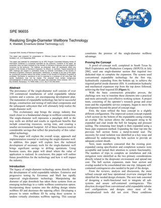
A proof–of–concept well, completed in South Texas by
Shell Exploration and Production Company (SEPCO) in July
2002, used one single-diameter section that required two
dedicated trips to complete the expansion. The system used
conventional expandable technology for the first trip,
hydraulically expanding from the bottom up, to achieve the
required partial inside diameter (ID). A combination hydraulic
and mechanical expansion trip from the top down followed,
achieving the final required ID (Figure 1).
With the basic construction principles proven, the
challenge now was to translate these elements into a practical
and more universally cost-effective working system. A project
team, consisting of the operator’s research group and asset
team and the expandable service company, began to move the
development beyond the proof of concept stage.
First, the team refined the base concept to a slightly
different configuration. The improved system concept expands
a bell section on the bottom of the expandable casing creating
an overlap. This section allows the subsequent string to be
expanded and clad inside the bell for hanging and pressure
sealing. The remaining liner length is then expanded using a
basic pipe expansion method. Expanding the liner top into the
previous bell section forms a metal-to-metal seal. The
necessity for zonal isolation was identified as a key issue and
addressed by underreaming the hole section to provide an
adequate cement sheath.
Next, team members concurred that the existing post-
expanded casing specification and completion scenario were
acceptable and turned their attention to system functionality.
The numbers of trips to complete an installation and risk
mitigation were identified as the two primary considerations
directly related to the deepwater environment and spread rate
cost. The bell section expansion, main liner section and
overlap needed to be consolidated into one trip. Adequate self-
contained contingencies also needed to be part of the design.
From the reviews, analysis and discussions, the more
refined concept and base operational overview emerged that
identified the needed design elements. The next task consisted
of designing a multi-functional tool to integrate all sub-
systems and assure self-contained contingencies. This
direction diverged from conventional solid expandable tubular
tool configurations and designs since most of the
conceptualized tools did not exist. These conditions
SPE 96655
Realizing Single-Diameter Wellbore Technology
K. Waddell, Enventure Global Technology LLC
2. 2 SPE 96655
necessitated an extensive design task to fulfill all of the
requirements.
The Tool String Elements and Contingencies
A deliberate and methodical planning, designing and
implementation philosophy produced a tool string that works
in conjunction with all subsystems and provides the means for
contingencies. This multi-functional tool consists of seven
major elements and three minor elements (Figure 2). From
top to bottom:
• Sizing mill – hydraulically activated tool used to cut and
pull excess casing/ballast casing clad in the bell section.
• Anchor – hydraulically activated tool used to anchor the
tension actuator to the casing during expansion. This
device is designed to grip in only one direction.
• Safety sub – specially threaded connection that has low
breakout torque. This device is used for contingency
release.
• Tension actuator – multiple piston hydraulic actuator that
is used to expand casing until the packer is set.
• Cup sub – provides surface area for hydraulic expansion.
• Casing lock – carries the weight of the casing as the tool
string moves down hole.
• Extender – hydraulically activated tool used to deploy the
cones and packer outside the case to initiate expansion.
• Expandable cones – hydraulically expanded and used to
form the bell section for the subsequent casing clad and
expand the main liner body. Sizes: 10.95 and 10.40 in.
• Packer setting tool – available as a mechanical setting tool
or a hydraulic setting tool.
• Packer – primarily used to seal off the end of the casing to
provide pressure integrity during hydraulic expansion and
as a retainer during cementing operations. The packer
contains a sliding valve to provide flexibility in the
cementing sequence.
The single-diameter tool string contingencies center on the
following key elements:
• Safety sub system – is based on a wavy shoulder low
torque connection. The box connection of the sub looks
up on the downhole single-diameter tool string. Its
counterpart pin connection looks down on the end of the
workstring. The system ties the inner liner workstring into
the single-diameter tool string/liner during liner
deployment operations.
During remediation operations, it can be backed-off to
retrieve the largest outside diameter (OD) tools, tension
actuator, anchor and sizing mill to provide maximum
flexibility for jarring or fishing operations. The sub and
connection are standard parts of solid expandable tubular
systems and have been run downhole trouble-free over
300 times.
• Tension actuator and anchor – provide the ability to
generate expansion force if there is a loss of hydraulic
integrity from a connection leak or casing breech. It is
also available should additional force be necessary
beyond the capacity of hydraulic expansion.
• Cones – equipped with a retracting device that is activated
by rupturing a 5,000 psi burst disk in the assembly. This
mechanism retracts both cones to a reduced drift OD.
Once completed, this contingency allows for the retrieval
of the tool string through the unexpanded casing ID.
Field Execution
The test well for the single-diameter expansion tool, in late
2004, was executed with a full Class III BOP stack, health,
safety and environmental (HSE) systems, closed loop mud
system and zero discharge tolerance. This live well was the
means by which the following objectives were satisfied:
• Full compliance with HSE policies and zero recordable
incidents
• Deploy and expand 9-5/8 in. single-diameter liners in the
well
• Test the merits of expansion against and into the
formation to achieve hydraulic isolation without cement
and/or mechanical isolation tools
To best facilitate system application, wellbore preparation
followed a carefully laid out plan. Below a 20 in. conductor at
101 ft, 16 in. structural casing was set at 450 ft followed by
11-3/4 in. surface casing set at 2,089 ft. The surface casing
string consisted of 65 lb/ft, L80 casing and three joints of 47
lb/ft, LSX-80, proprietary expandable casing and connections.
This casing string served as the shoe track and the pre-formed
bell section for cladding back the subsequent single-diameter
liner with a metal-to-metal expansion and 100% hydraulic
seal.
A pendulum assembly with a 10.25 in. rock bit and near-
bit reamer, pinned for a 12-1/2 in. hole, drilled the +500 ft
hole section for deployment of the 9-5/8 in., 36 lb/ft, LSX-80
expandable liner and the concentric single-diameter tool string
assembly. After cementing the surface casing, the shoe track
was drilled out with a 10.25 in. bit, short collar and one-degree
bent sub. This assembly cleaned out cement without damaging
the face of the surface casing, which was subsequently used to
expand against with the expanded liner. Running an
expandable liner requires specialized casing handling
equipment and procedures to protect the OD of the casing and
connections.
The Single-diameter Expansion Process
To help facilitate deployment of the single-diameter expansion
system an installation process was developed in conjunction
with the tool. After hole preparation, two casing joints are run
in the hole with the bottom part of the single-diameter tool
string assembly pre-installed inside the casing. Several joints
of casing are then run inside the surface casing followed by
the tool string that is deployed inside the casing. Both the
casing and the concentric tool string are then run in the hole
simultaneously using a false rotary table. When on bottom, the
casing and tool string is picked up approximately 50 ft, and a
dart is pumped. The pumped dart actuates the extender, which
pushes the packer and cones outside the liner and the casing
locks retract. Once outside the casing, hydraulic pressure
opens the upper cone assembly to its full 10.95 in. OD and the
lower cone to its full 10.40 in. OD. Pressure cycles begin to
mechanically expand the bottom joint of casing to 10.95 in.
ID, which forms the bell section and allows expanding back
the next single-diameter liner inside the bell with metal-to-
metal expansion (Figure 3 – Stage 1).
3. SPE 96655 3
Once the bell section is formed, the pressure is released
and the upper cone is retracted and pulled up inside the
unexpanded liner. The 10.40 in. cone assembly is pulled up
against the expansion face (Figure 3 – Stage 2). After
expanding the first two joints, the rest of the liner can either be
mechanically or hydraulically expanded (Figure 4 – Stage 3).
If hydraulically expanded, the packer is mechanically set by
rotating in the expanded 10.40 in. liner. Cement is pumped
below the packer for stability on the drillout and on the
backside if annular cement isolation is desired.
After cement is in place, the remainder of the liner is
hydraulically expanded up into the surface casing shoe track.
Options for the liner-to-casing seal include the following
proven techniques:
• Metal-to-metal seal by expanding the liner to 10.40 in. ID
and 11.00 in. OD inside the 47 lb/ft, 11.75 surface casing.
• Conventional elastomers run on the top two to three liner
joints. (The metal-to-metal seal was used in the subject
test. Subsequent cased-hole logging and positive pressure
testing indicated a solid hydraulic seal in the expandable
liner lap area.)
Upon completing expansion, the tool string is pulled to the
surface and laid down. A proprietary sizing mill assembly is
run inside the casing and pulled up into the 10.40 in.
expanded/unexpanded casing interface (Figure 4 – Stage 4).
The sizing mill arms extend to cut the liner. Both the tool
string and the cut, unexpanded casing is pulled to surface and
laid down. A cased-hole casing evaluation log follows each
expansion to assess expansion faces, expansion ovality and
casing condition. In the actual field application, all subject
logs indicated highly uniform expansion IDs with minimal to
no ovality and minimal distortion of the cutting face.
Actualizing the Potential
Solid expandable tubular technology was primarily designed
to address conditions that lead to casing being set before
planned. Using the technology to cover a swelling shale or lost
circulation zone allows drilling to continue with only a
fraction of hole size loss if using conventional expansion
systems, or no hole size loss if using single-diameter systems.
During the course of its short history, solid expandable
tubulars have demonstrated substantial cost savings and value
generation through a variety of downhole applications
including:
• Expanding solid tubulars through milled window exits.1
• Incorporating expandable tubulars into the drilling
design.2
• Installing 13Cr solid expandable systems to maximize gas
production.3
While the numbers generated from these enabling installations
have been significant, they have been achieved on a single-
well basis. What have not been fully delineated or explored
are the full enabling possibilities of the technology in full-
blown field developments.
The advantage of using solid expandable technology in a
multi-well or field development is in leveraging the cost
savings and value creation to be multiplied over the entire
scope of the project. Therefore, the magnitude of the savings
and value are greatly increased. These significant cost savings
and value are realized through the technology’s ability to
• Reduce drilling-related risk and trouble time
• Improve capital efficiency on drilled wells and overall
field development by reducing well cost and structure size
• Enhance field-development flexibility including
scheduling and planning
• Reduce cost-structure in field development
• Accelerate reserves
Pushing the Envelope
A legacy of successful installations, a broadening applications
envelope, and continued development has led to the next
evolutionary step in the technology - single-diameter solid
expandable tubulars. Like its conventional predecessor, single-
diameter advancement depends on a sound value proposition
to progress the technology from field testing to the asset level.
A specific application with field-development repercussions
has garnered much attention for its substantial business case.
This application consists of marrying single-diameter
technology and extended reach drilling (ERD). The coupling
of these two leading edge technologies will positively impact
well and field capital and operational cost in several key areas,
resulting in economically viable alternative development
scenarios.
Expandable technology is seen as a way to reduce the
overall non-productive time (NPT) incurred during the
construction of an extended reach well. By addressing drilling
problems as they occur and casing off challenging intervals
without any loss of diameter, great improvements in
operational efficiency will be gained.
The technology’s proven, simulated and engineered
potential provides the foundation for a significant increase in
the lateral reach of many extended reach wellbores.5
Torque
and drag on an extended reach well is often seen as the critical
factor that limits achievable reach. Geometric conditions such
as dogleg severity (DLS) and casing openhole size vs. drill
string size can influence torque and drag as well. Successive
installations of expandable, single-diameter systems can
significantly reduce the friction/drag forces that can limit
lateral reach and still preserve ID as required. In turn these
systems can afford higher weight-on-bit at comparable depths
versus conventional drilling technology. The current envelope
for ERD is ~10,000 m, and by using solid expandable tubular
technology with significant friction reduction, the envelope
could be extended another 5,000 m (Figure 5).
This extended lateral reach results in increased reservoir
contact that can lead to increased production per well. More
production from fewer wells can ultimately lower required
field well counts with an improved drilling cost structure
profile. In select offshore applications, this technology can in
turn result in lower platform installation requirements without
reserve reductions. The potential exists to increase reserves by
tapping flank or step-out reserves. In many subsea
applications, the technology can result in fewer subsea
templates, flowlines, pipelines and production center
requirements (Figure 6). Optimizing drilling operations can
lower facility and project capital requirements while
improving platform or subsea facility installation flexibility
4. 4 SPE 96655
and phasing. Enhancing development flexibility with
minimum economics is an attractive proposition. In subsea
applications improved development phasing includes seabed
geohazards, such as escarpments or Arctic iceberg risks.
Reducing the subsea infrastructure requirements further
mitigates project risk and improves field economic returns
(Figure 7).
Additional Advantages
Capitalizing on the possibilities has taken solid expandable
technology from a contingency system to a viable drilling plan
option to an instrumental factor in designing the task-specific
rig. This approach incorporates single-diameter technology to
work as part of an overall system that downsizes well
infrastructure without compromising the bottomhole
completion. The system includes a smaller wellhead,
Christmas tree and riser. These reductions lower the overall
capital cost for a take-point which in turn makes sub-sea
targets and marginal reserves more economically feasible.
An application advantage exists in the form of using
single-diameter tubulars to extend the shoe during drilling
operations without reduction of ID. This application is
particularly advantageous in exploration wells where the
drilling hazards are not well defined or are unknown. By using
the technology to extend the shoe and maintain ID, the
operator is guaranteed a workable ID at target depth for
production testing or to run evaluation tools.
Another meritable by-product to emerge from using solid
expandable tubular technology is its environmental appeal.
Many of the same factors that reduce expenditures, such as
downsizing, also reduce the environmental footprint of these
operations—less mud required, fewer cuttings needing
disposal, smaller rigs that create less of a disturbance to the
area.
Conclusion
The successful application of solid expandable technology
over the past six years has fed the development of single-
diameter wellbore technology. The proficiency being gained
with this unique and exclusive technology serves to further its
evolution. Proving reliability and establishing economic
advantage of expandable technology reinforces the projected
potential of the single-diameter concept that will usher in a
paradigm shift in wellbore construction6
and field
development. The industry is only recently beginning to
realize the many profitable applications of single-diameter
expansion systems.
As the market for hydrocarbon fuels continues to grow so
will the burden to find and develop oil and gas fields.
Exploration and production will require technology that goes
not only further and faster but provide maximum flexibility,
reliability and value. Solid expandable tubular systems have
demonstrated their ability to extend drilling depths at a faster
rate. This technology is already impacting drilling operations
with advantages that encompass saving time and reducing
drilling costs to decreasing the environmental disturbance
during drilling and production operations. The viability of
current systems and the promise of developing technology
continue to drive the evolution of expandables. But the effort
to make the single-diameter wellbore a practical construction
option cannot be driven by service companies alone. A key to
realizing the single-diameter well lies in the industry’s
willingness to accept, apply, and promote expansion of the
technology’s enabling capability, benefits, and potential.
References
1. Grant, T., Enventure Global Technology; Inventive Solid
Expandable Tubular Applications Capitalize on Window of
Opportunity: Openhole Liner System Prevents Loss of Hole
Size in Sidetracking Operations; AADE-05-NTCE-19
AADE 2005 National Technical Conference and
Exhibition, held at the Wyndam Greenspoint in Houston,
Texas, April 5-7, 2005.
2. Carstens, C., Unocal Corporation; Blasingame, K.,
Enventure Global Technology; Solid Expandable Tubular
Technology: The Value of Planned Installation Vs.
Contingency; SPE/IADC 92622 SPE/IADC Drilling
Conference held in Amsterdam, The Netherlands, 23-25
February 2005.
3. Siemers, G. and Ukomah, T., NAM; Mack, R., Shell; and
Noel, G., and Donald, J., Enventure Global Technology;
Development and Field Testing of Solid Expandable
Corrosion Resistant Cased-hole Liners to Boost Gas
Production in Corrosive Environments; OTC 15149 2003
Offshore Technology Conference held in Houston, Texas,
U.S.A., 5–8 May 2003.
4. DeMong, K., Halliburton; Rivenbark, M., Enventure
Global Technology; Hussain, K., Kuwait Oil Company;
Planning the Well Construction Process for the Use of
Solid Expandable Casing, SPE 85303 SPE/IADC Middle
East Drilling Technology Conference & Exhibition held in
Abu Dhabi, UAE, 20-22 October 2003.
5. DeMong, K., Halliburton; Rivenbark, M., Enventure
Global Technology; Breakthroughs Using Solid
Expandable Tubulars to Construct Extended Reach Wells,
SPE 87209 IADC/SPE held in Dallas, Texas USA, March,
2004.
6. Waddell, K., Enventure Global Technology; Advances in
Monodiameter Well Technology: The Next Step to Cost-
Effective Optimization, SPE 90818 SPE Annual Technical
Conference and Exhibition held in Houston, Texas, U.S.A.,
26–29 September 2004.
5. 5 SPE 96655
Figure 1 – Illustration of top-down expansion process.
Figure 2 – Single-diameter tool string with major and minor elements.
Step 1
Run conventional
bottom-up system and
clad
Step 2
Drill out bottom
plug
Step 3
Run top-down system;
over expand previous
casing
Step 4
Drill ahead and run
next section