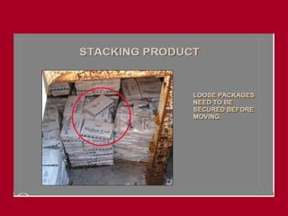
OBJECTIVES
• Lifting OperationsAnd LOLER 1998 (LOLER).
• Definitions And Terminologies In Lifting Operation.
• Types Of Lifts And Their Classification
• Types Of Hitches And Angle Factors
• Planning A Lift
• Weight Load Calculation
• Common Types Of Slings, Rigging Gear And Their
Inspection
• Lifting a Load
• Load Charts And Tables
• Crane Terminologies And Basic Load Chart
Understanding
2.
DEFINITIONS
• Lifting Equipment
•Work equipment for lifting or lowering loads and
including its attachments used for anchoring, fixing
or supporting it.
• Ex: chain hoist, cranes, fork trucks etc
• Lifting Accessory (Lifting Gear)
• work equipment used for attaching loads to
machinery for lifting.
• Ex: wire rope slings, shackles, webbing slings,
eyebolts, swivels etc..
3.
DEFINITIONS
• Operative
– Anoperative is a trained person actually using the
equipment.
• Responsible Person
– A Responsible Person is a person who has sufficient
knowledge and training to enable him/her to recognise
obvious defects and is responsible to his/her employer
for the 'in-service' inspection of equipment.
4.
DEFINITIONS
• Competent Person
–A Competent Person is the person concerned with the
testing, examination and certification of lifting equipment.
– He/she should have such practical and theoretical
knowledge and experience of the equipment which is to be
tested, examined and certified that will enable him/her to
detect defects or weaknesses which it is the purpose of
the examination to discover and to assess their
importance to the safety of the equipment. (Third party
lifting Inspector)
5.
DEFINITIONS
• In-service Inspection
–In-service inspection is a visual inspection
carried out by a Responsible Person to check
for obvious signs of damage or wear which
might affect the equipment's fitness for use.
6.
DEFINITIONS
• Thorough Examination
–A Thorough Examination is an examination carried out by a
Competent Person carefully and critically, and where necessary
supplemented by other means such as measurement and non-
destructive testing, in order to detect damage or deterioration.
– The period between thorough examinations shall be established
by management on the basis of statutory requirements for the
equipment, severity of service conditions, nature of the lifts,
prior experience and the recommendation of the Competent
Person.
– In no case shall the period between thorough examinations
exceed the statutory period.
7.
DEFINITIONS
• Proof orTest Load
– A load (mass or force) applied by the manufacturer or
Competent Person for the purpose of a test. This load
appears on test certificates.
• Minimum Breaking (or Failure) Load (MBL)
– The specified load (mass or force) below which the item of
equipment does not fail either by fracture or distorting to such an
extent that the load is released.
• Mass Units are usually tonnes (t)
• Force units are usually Newton (N)
8.
DEFINITIONS
• Working LoadLimit (WLL)
– The maximum load (mass) that an item of lifting
equipment is designed to raise, lower or suspend. In
some standards and documents the WLL is referred
to as the 'maximum safe working load'.
• Factor of Safety
– The ratio between MBL and WLL identified on the
test certificate as the Coefficient of Utilisation.
– E.G. MBL = 5t, WLL = 1t F.O.S. = 5:1
9.
DEFINITIONS
• Safe WorkingLoad (SWL)
– The maximum load (mass), as assessed by a
Competent Person, which an item of lifting equipment
may raise, lower or suspend under the particular
service conditions. The SWL will normally be the
same as the working load limit or the maximum safe
working load, where the term is used but it may be
less. The SWL appears in statutory records.
10.
DEFINITIONS
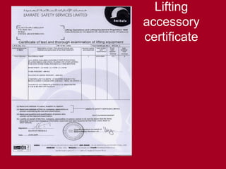
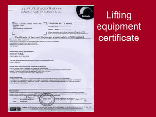
• Test Certificate
–A certificate issued by the Competent Person giving
details of tests, conducted on an item of lifting
equipment.
11.
DEFINITIONS
• Examination Report
–A certificate issued by a Competent Person
giving the results of the thorough examination
including testing if appropriate. This will detail
the defects found or include a statement that
the item is fit safe to operate.
UAE LAW
Law governingINDUSTRIAL SAFETY
AND LIFTING OPERATIONS enacted
in 1982 in form of Ministerial Decree No.
32 for that year.
17.
Article (20) Cranes& Lifting Equipment
• Following to be noted regarding lifting &
pulling machines & tools:
a. Cranes & lifts for men & materials shall be of
sound construction & manufacture, regularly
maintained & checked by a qualified
technician at once ever 12 months.
b. Area where lifts fitted shall be fenced in such
way as to prevent access or egress while
moving.
18.
c. Chains, ropes,wire ropes & other lifting
equipment shall be continuously & completely
maintained & checked by a qualified
technician at least once every 6 months.
d. The maximum capacity of machine / lift shall
be displayed in a prominent position.
e. An employee may not be asked to carry loads
above his capacity, & in any case no load
shall exceed 50kg per man & 20kg per
woman, & where possible mechanical lifting
equipment shall be used.
19.
Section (a):Qualified inspector defined by
Ministry of Labour issuing approvals to
carry out inspection & testing to certain
organisations & personnel within it.
(Before using crane, loose lifting gear &
points, ensure it is certified.)
20.
Periodicity of Examinations(LOLER)
• Under LOLER, all lifting equipment &
accessories examined & tested (where
appropriate):
before it is put to service for first time (unless it
hasn’t been used before &/or it has an EC
declaration of conformity less than 12 months
old)
after installation / assembly at new site (if safety
of equipment is dependent on installation
conditions)
21.
at specified intervalsdependent on
operational circumstances as follows:
• lifting equipment used for lifting persons – at
least every 6 months
• lifting accessories – at least every 6 months
• any other lifting equipment – at least every 12
months
each time exceptional circumstances which
are liable to jeopardise safety of lifting
equipment has occurred.
22.
Planning
• Lifting /cargo handling operations – each
job is different & for safety all have to be
planned
• Depth of planning increases with complexity
of job
• Numerous factors to be considered:
weight of load
position / height of centre of gravity
stability of load
23.
size & shapeof load
availability of dedicated lifting points on load
availability of suitable rigging
protection of rigging against sharp edges
capacity of crane / hoisting equipment
availability of certified anchor points / support
steelwork
available headroom
route to be travelled
obstructions
24.
maximum height loadhas to be lifted
any dynamic factors
hazards to other personnel
number of banksmen required
communication
deck / floor capacity for landing load
need for tag lines
available light
experience / competence of personnel
25.
Types of Lifts
Routine Lifts: performed on regular
basis – involves basic slinging
practices – e.g. containers, etc.
Planning: use of generic plans &/or
toolbox talks usually adequate for this
level of lifting operation
26.
• Simple Lifts:involve use of basic hoisting
equipment directly above the head (e.g. –
crane / manual hoist suspended from
dedicated lifting structures such as pad
eyes / runway beams). Load required to
have certified lifting points / easy to sling
Planning: use of generic plans &/or
toolbox talks usually adequate for this
level of lifting operation
27.
Complicated Lifts:difficult due to nature of
load (e.g. awkward shape, offset / high
centre of gravity, fragility, containing liquids,
no lifting attachments / difficulty to sling,
etc.)
actual lifting operation / handling of lift may
be difficult (e.g. may require to be rotated /
cross-hauled involving two / more sets of
rigging &/or tandem lifting with cranes).
Planning: written plan with toolbox talks
required
28.
• Complex Lifts:could be any of the above
categories – additional hazards, i.e. lifting
operations / conditions which would merit
additional engg. input (e.g. extremely
heavy loads, confined spaces, restricted
headroom, lifting over unprotected plant /
equipment & lifts involving divers / floating
cranes, etc).
Planning: written plan / job pack with
toolbox talks required
29.
Activity 1.
• Giveexamples of simple, routine,
complicated and complex lifts.
• Questions on LOLER 1998.
• Case study on different loads and
conditions.
30.
Slinger requirement
1. Either18years of age or under the direct supervision of
competent person for training
2. In good health, eyesight, reflexes and agility and able to
handle lifting accessories
3. Able to establish weights, balance loads, judge
distances, heights and clearances
4. Trained in technique of slinging and selection of rigging
material.
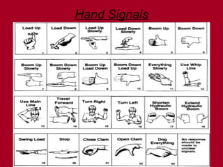
5. Able to give right hand signals and communicate the
lifting operation
6. Capable of initiating and directing movement of crane
and load.
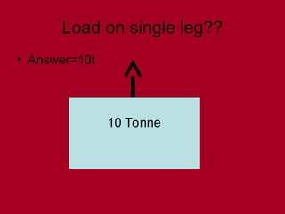
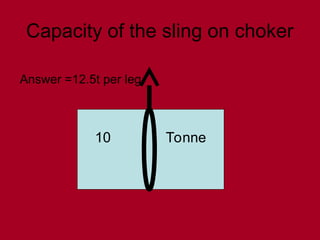
Capacity of thesling on choker
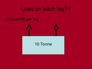
10 Tonne
Answer =12.5t per leg
34.
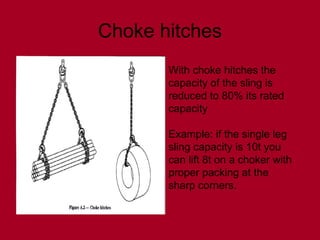
Choke hitches
With chokehitches the
capacity of the sling is
reduced to 80% its rated
capacity
Example: if the single leg
sling capacity is 10t you
can lift 8t on a choker with
proper packing at the
sharp corners.
35.
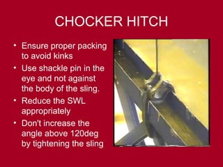
CHOCKER HITCH
• Ensureproper packing
to avoid kinks
• Use shackle pin in the
eye and not against
the body of the sling.
• Reduce the SWL
appropriately
• Don't increase the
angle above 120deg
by tightening the sling
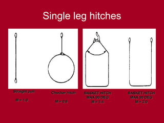
Single leg hitches
Straightpull
Straight pull
M = 1.0
M = 1.0
Chocker hitch
Chocker hitch
M = 0.8
M = 0.8
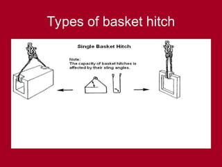
BASKET HITCH
BASKET HITCH
MAX 90 DEG
MAX 90 DEG
M = 1.4
M = 1.4
BASKET HITCH
BASKET HITCH
MAX 90 DEG
MAX 90 DEG
M = 2.0
M = 2.0
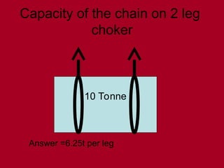
Capacity of thechain on 2 leg
choker
10 Tonne
Answer =6.25t per leg
43.
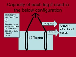
Capacity of eachleg if used in
the below configuration
10 Tonne
Answer:
=8.75t and
above
Choker hitch
Two leg sling
Single leg will
take 70% of the
load
=7t
Because the leg
is used in choker
the capacity is
reduces to 80%
= 7t / 0.8
=8.75t
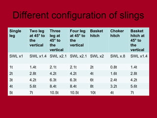
Different configuration ofslings
Single
leg
Two leg
at 45° to
the
vertical
Three
leg at
45° to
the
vertical
Four leg
at 45° to
the
vertical
Basket
hitch
Choker
hitch
Basket
hitch at
45° to
the
vertical
SWL x1 SWL x1.4 SWL x2.1 SWL x2.1 SWL x2 SWL x.8 SWL x1.4
1t 1.4t 2.1t 2.1t 2t 0.8t 1.4t
2t 2.8t 4.2t 4.2t 4t 1.6t 2.8t
3t 4.2t 6.3t 6.3t 6t 2.4t 4.2t
4t 5.6t 8.4t 8.4t 8t 3.2t 5.6t
5t 7t 10.5t 10.5t 10t 4t 7t
47.
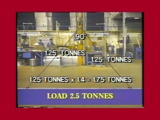
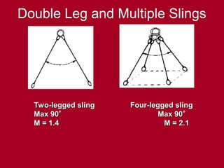
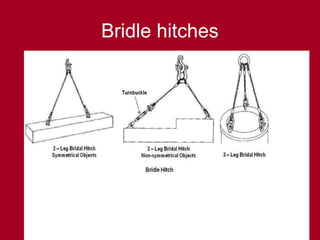
Double Leg andMultiple Slings
Two-legged sling
Two-legged sling Four-legged sling
Four-legged sling
Max 90
Max 90
Max 90
Max 90
M = 1.4
M = 1.4 M = 2.1
M = 2.1
48.
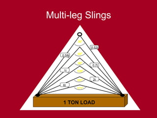
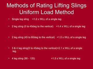
Methods of RatingLifting Slings
Uniform Load Method
• Single leg sling =1.0 x WLL of a single leg
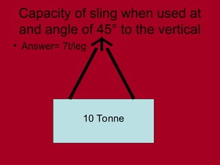
• 2 leg sling (0 to 45deg to the vertical) =1.4 x WLL of a single leg
• 2 leg sling (45 to 60deg to the vertical) =1.0 x WLL of a single leg
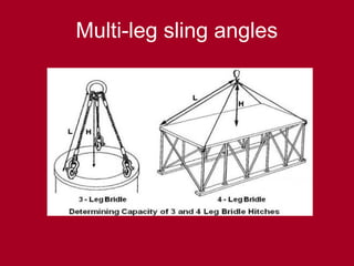
• 3 & 4 leg sling(0 to 45deg to the vertical)=2.1 x WLL of a single
leg.
• 4 leg sling (90 - 120) =1.5 x WLL of a single leg
49.
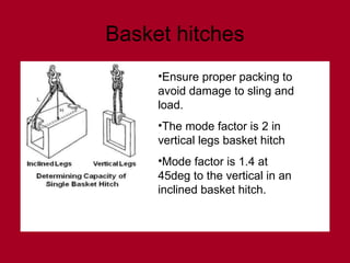
Basket hitches
•Ensure properpacking to
avoid damage to sling and
load.
•The mode factor is 2 in
vertical legs basket hitch
•Mode factor is 1.4 at
45deg to the vertical in an
inclined basket hitch.
Center Of Gravity
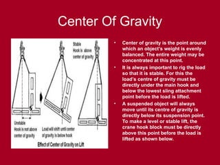
•Center of gravity is the point around
which an object’s weight is evenly
balanced. The entire weight may be
concentrated at this point.
• It is always important to rig the load
so that it is stable. For this the
load’s centre of gravity must be
directly under the main hook and
below the lowest sling attachment
point before the load is lifted.
• A suspended object will always
move until its centre of gravity is
directly below its suspension point.
To make a level or stable lift, the
crane hook block must be directly
above this point before the load is
lifted as shown below.
57.
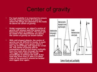
Center of gravity
•For load stability it is important to ensure
that the support points of a load (i.e.
where the slings are attached to the load)
lie above its centre of gravity.
• Under suspension, an object’s centre of
gravity will always seek the lowest level
below the point of support. The load will
be stable if the attachments are above
the centre of gravity as shown below.
• With odd shaped objects, the centre of
gravity can be difficult to locate. In such
cases the rigger must guess where it
lies, rig accordingly and signal for a trial
lift. The centre of gravity will lie
somewhere along a line drawn vertically
from the hook down through the load.
The rigger than adjust the slings
accordingly to balance the load. If any
load tilts more than 5º after it is lifted
clear of the ground it should be landed
and rigged over again.
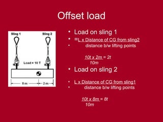
Offset load
• Loadon sling 1
• =L x Distance of CG from sling2
• distance b/w lifting points
10t x 2m = 2t
10m
• Load on sling 2
• L x Distance of CG from sling1
• distance b/w lifting points
10t x 8m = 8t
10m
60.
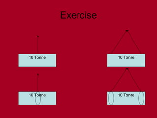
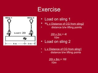
Exercise
20t
• Load onsling 1
• =L x Distance of CG from sling2
• distance b/w lifting points
20t x 2m = 4t
10m
• Load on sling 2
• L x Distance of CG from sling1
• distance b/w lifting points
20t x 8m = 16t
10m
61.
Lifting Points
• Inpractice, unlikely that total load will be
evenly distributed amongst all lifting points.
• Actual load distribution will depend on a
number of factors including construction of
plant (e.g. flexibility of structure, sling
length, tolerances etc.).
62.
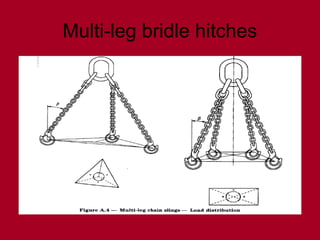
• It isrecommended to assume that in a 4
point lift situation, 75% of the load is
distributed between two diagonally opposite
legs, the third leg supports 25% of the load
& the fourth leg is redundant.
• This equates to a possible increase in load
on each lifting point of 50%.
• Hence each lifting point shall have a rated
load of not less than 1.5 times the share of
the load which it is intended to take when
the load is applied vertically.
63.
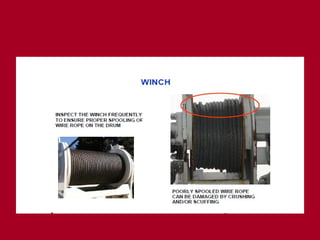
Moving a Load
•Centre the hook over the CG of the load.
Ensure correct spooling of rope, prevent
load from swinging when it is lifted.
• Use a tag line when loads must traverse
long distances or must otherwise be
controlled. Manila rope may be used for
tag lines.
64.
• Plan &check the travel path to avoid
personnel & obstructions.
• Lift the load only high enough to clear the
tallest obstruction in the travel path.
• Start and stop slowly.
• Land the load when the move is finished.
Choose a safe landing.
65.
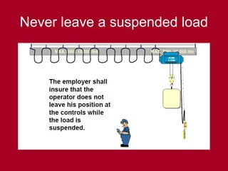
• NEVER leavesuspended loads
unattended. In an emergency where the
crane / hoist has become inoperative & if a
load must be left suspended, barricade &
post signs in the surrounding area, under
the load & on all four sides. Lock open &
tag the crane / hoist's main electrical
disconnect switch.
67
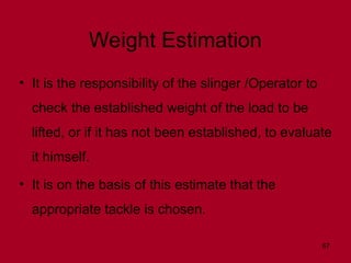
Weight Estimation
• Itis the responsibility of the slinger /Operator to
check the established weight of the load to be
lifted, or if it has not been established, to evaluate
it himself.
• It is on the basis of this estimate that the
appropriate tackle is chosen.
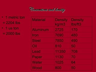
• 1 metricton
= 2204 lbs
• 1 us ton
= 2000 lbs
Material Density
kg/m3
Density
lbs/ft3
Aluminum 2725 170
Iron 7690 480
Steel 7850 490
Oil 810 50
Lead 11350 708
Paper 1130 70
Water 1025 64
Wood 800 50
Conversions and density
Conversions and density
70.
70
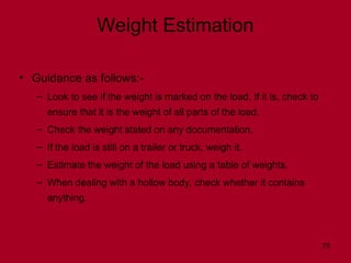
Weight Estimation
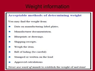
• Guidanceas follows:-
– Look to see if the weight is marked on the load. If it is, check to
ensure that it is the weight of all parts of the load.
– Check the weight stated on any documentation.
– If the load is still on a trailer or truck, weigh it.
– Estimate the weight of the load using a table of weights.
– When dealing with a hollow body, check whether it contains
anything.
71.
71
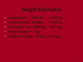
Weight Estimation
• 1imperial ton = 2240 lbs. =1016 Kg.)
• 1 metric tonne = 2204lbs =1000 Kg.
• 1 American Ton = 2000 lbs. =907 Kg)
• 1 Litre of water = 1 Kg.
• 1 Gallon of water = 10 Lbs. (4.54 Kg.)
72.
72
2 m.
3 m.
4m.
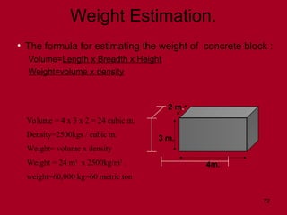
WeightEstimation.
• The formula for estimating the weight of concrete block :
Volume=Length x Breadth x Height
Weight=volume x density
Volume = 4 x 3 x 2 = 24 cubic m.
Density=2500kgs / cubic m.
Weight= volume x density
Weight = 24 m3
x 2500kg/m3
.
weight=60,000 kg=60 metric ton
73.
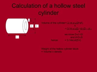
Calculation of ahollow steel
cylinder
D
t
d
L
Volume of the cylinder= 3.14 x L(D2-
d2
)
4
= 3.14 x L(D +
d) (D – d )
4
we know D-d =2t
and d=D-2t
hence: = 3.14xLxt(D-t)
Weight of the hollow cylinder block
= Volume x density
74.
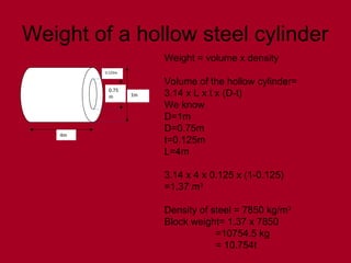
Weight of ahollow steel cylinder
1m
0.125m
0.75
m
4m
Weight = volume x density
Volume of the hollow cylinder=
3.14 x L x t x (D-t)
We know
D=1m
D=0.75m
t=0.125m
L=4m
3.14 x 4 x 0.125 x (1-0.125)
=1.37 m3
Density of steel = 7850 kg/m3
Block weight= 1.37 x 7850
=10754.5 kg
= 10.754t
75.
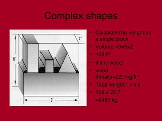
Complex shapes
• Calculatethe weight as
a single block
• Volume =9x6x2
• 108 ft3
• If it is wood
• wood
density=22.7kg/ft3.
• Total weight= v x d
• 108 x 22.7
• =2451 kg
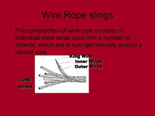
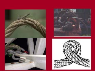
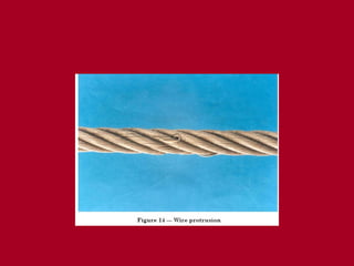
Wire Rope slings
•The construction of wire rope consists of
individual steel wires spun into a number of
strands, which are in turn laid helically around a
central core
King Wire
King Wire
Inner Wires
Inner Wires
Outer Wires
Outer Wires
CORE
CORE
Strand
Strand
80.
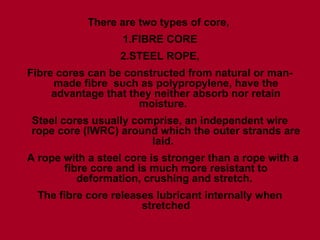
There are twotypes of core,
1.FIBRE CORE
2.STEEL ROPE,
Fibre cores can be constructed from natural or man-
made fibre such as polypropylene, have the
advantage that they neither absorb nor retain
moisture.
Steel cores usually comprise, an independent wire
rope core (IWRC) around which the outer strands are
laid.
A rope with a steel core is stronger than a rope with a
fibre core and is much more resistant to
deformation, crushing and stretch.
The fibre core releases lubricant internally when
stretched
81.
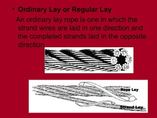
• Ordinary Layor Regular Lay
An ordinary lay rope is one in which the
strand wires are laid in one direction and
the completed strands laid in the opposite
direction
Rope Lay
Rope Lay
Strand Lay
Strand Lay
82.
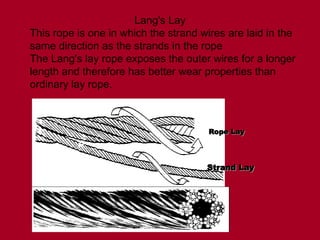
Lang's Lay
This ropeis one in which the strand wires are laid in the
same direction as the strands in the rope
The Lang's lay rope exposes the outer wires for a longer
length and therefore has better wear properties than
ordinary lay rope.
Rope Lay
Rope Lay
Strand Lay
Strand Lay
83.
The ordinary layrope is easier to handle,
more resistant to crushing and distortion
and is the more commonly used.
The majority of ropes are of right-hand lay,
although occasionally left-hand lay ropes
can be supplied. The direction of rope lay
is important, to ensure correct coiling and
spooling of the rope .
84.
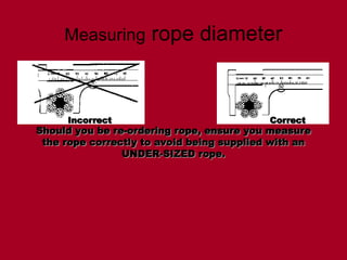
Measuring rope diameter
Correct
Correct
Incorrect
Incorrect
Shouldyou be re-ordering rope, ensure you measure
Should you be re-ordering rope, ensure you measure
the rope correctly to avoid being supplied with an
the rope correctly to avoid being supplied with an
UNDER-SIZED rope.
UNDER-SIZED rope.
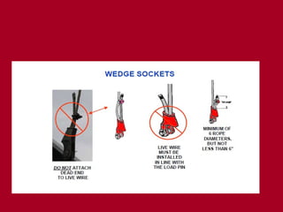
85.
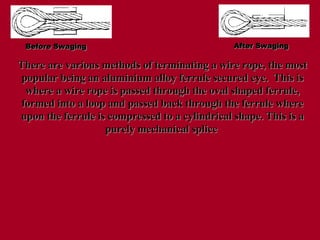
Before Swaging
Before SwagingAfter Swaging
After Swaging
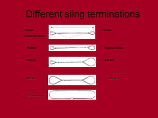
There are various methods of terminating a wire rope, the most
There are various methods of terminating a wire rope, the most
popular being an aluminium alloy ferrule secured eye. This is
popular being an aluminium alloy ferrule secured eye. This is
where a wire rope is passed through the oval shaped ferrule,
where a wire rope is passed through the oval shaped ferrule,
formed into a loop and passed back through the ferrule where
formed into a loop and passed back through the ferrule where
upon the ferrule is compressed to a cylindrical shape. This is a
upon the ferrule is compressed to a cylindrical shape. This is a
purely mechanical splice
purely mechanical splice
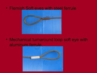
87.
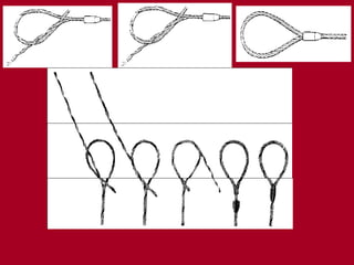
Flemish eye
• Thismethod of making an eye actually produces a stronger
securing than the turn back loop, ie the termination is more
efficient.
• To make a Flemish eye, a tapered steel ferrule is passed over
the rope. The standing part of the rope is then taken and three
strands are unravelled and opened so that a ‘Y’ formation is
made.
• The leg of the ‘Y’ that includes the core is bent to form an eye so
that the ends of the strands sit against the undisturbed part of the
rope at the bottom of the ‘Y’. The remaining three strands are
then re-laid into the rope in the opposite direction, taking up the
position they originally had in the rope so that the lay of the
strands is not disturbed. The ends of the strands are then evenly
distributed around the intact standing part of the rope to
complete the eye. The ferrule is then slid back over the
distributed wires without displacing the strands and then
pressed. In this case the ferrule compresses and grips the rope.
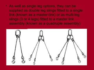
• As wellas single leg options, they can be
supplied as double leg slings fitted to a single
link (known as a master-link) or as multi-leg
slings (3 or 4 legs) fitted to a master link
assembly (known as a quadruple assembly)
93.
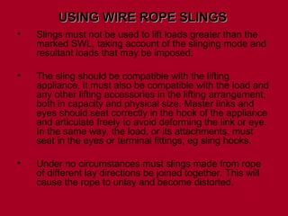
• Slings mustnot be used to lift loads greater than the
marked SWL, taking account of the slinging mode and
resultant loads that may be imposed.
• The sling should be compatible with the lifting
appliance, it must also be compatible with the load and
any other lifting accessories in the lifting arrangement,
both in capacity and physical size. Master links and
eyes should seat correctly in the hook of the appliance
and articulate freely to avoid deforming the link or eye.
In the same way, the load, or its attachments, must
seat in the eyes or terminal fittings, eg sling hooks.
• Under no circumstances must slings made from rope
of different lay directions be joined together. This will
cause the rope to unlay and become distorted.
USING WIRE ROPE SLINGS
USING WIRE ROPE SLINGS
94.
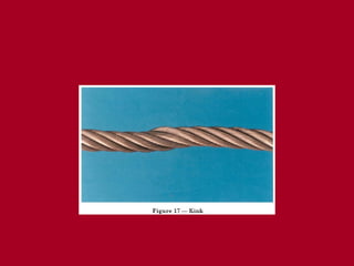
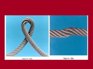
• Under nocircumstances should the radius formed be
less than four times the rope diameter. Suitable packing
should also be used. If this is not done the rope will be
permanently kinked, crushed or, at worst, cut. In any
event a sling that is repeatedly taken around corners and
than loaded will take on a set, this may make the sling
difficult to handle but will only be harmful if other damage
is done to the rope.
• Shock loading must be avoided otherwise the core or
inner wires will become damaged.
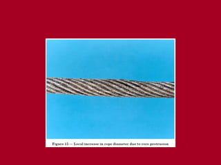
95.
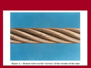
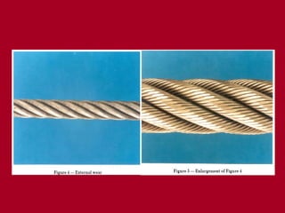
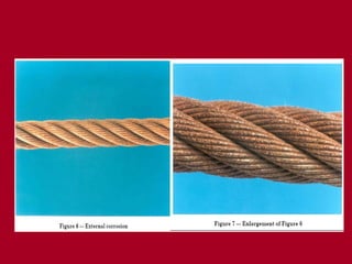
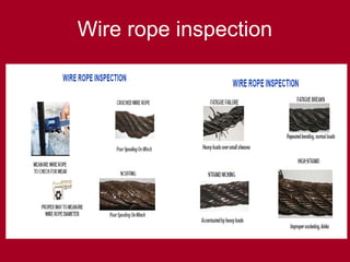
EXAMINATION
• THE SWLIS ADEQUATE FOR THE LOAD
• COLOR CODING AND ID ARE CLEAR.
• EXAMINE EACH INDIVIDUAL LEG,CHECK FOR CORROSION,
WEAR, ABRASION AND MECH DAMAGE AND BROKEN WIRES
• EXAMINE EACH FERRULE FOR CRACKS AND DAMAGE.
CHECK THE END OF ROPE PROTUDES SLIGHTLY NOT MORE
THAN HALF THE DIA
• CHECK THIMBLES FOR DAMAGE AND ELONGATION ,
CORRECT FITTING.(STRECHTED THIMBLES COULD INDICATE
OVERLOAD)
• WIRE ROPE WEAR ESPECIALLY AROUND THIMBLES
• CHECK TERMINATIONS LIKE MASTER LINKS AND HOOKS
FOR DAMAGE, CRACKS, NICKS, CORROSION AND SAFETY
CATCH.
Chain Slings andFittings
• Alloy grade 80 chain slings were
developed to replace the older mild steel
and high tensile chain slings
• Grade 80 chain slings are constructed
from individual components which can be
assembled in numerous configurations to
suit the task in hand.
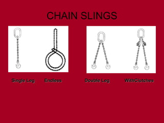
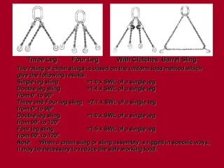
Three Leg
Three LegFour Leg
Four Leg With Clutches
With Clutches Barrel Sling
Barrel Sling
The rating of chain slings is based on the uniform load method which
The rating of chain slings is based on the uniform load method which
give the following results:
give the following results:
Single leg sling
Single leg sling =1.0 x SWL of a single leg
=1.0 x SWL of a single leg
Double leg sling
Double leg sling =1.4 x SWL of a single leg
=1.4 x SWL of a single leg
from 0° to 90°
from 0° to 90°
Three and Four leg sling
Three and Four leg sling =2.1 x SWL of a single leg
=2.1 x SWL of a single leg
from 0° to 90°
from 0° to 90°
Double leg sling
Double leg sling =1.0 x SWL of a single leg
=1.0 x SWL of a single leg
from 90° to 120°
from 90° to 120°
Four leg sling
Four leg sling =1.5 x SWL of a single leg
=1.5 x SWL of a single leg
from 90° to 120°
from 90° to 120°
Note:
Note: When a chain sling or sling assembly is rigged in specific ways,
When a chain sling or sling assembly is rigged in specific ways,
it may be necessary to reduce the safe working load.
it may be necessary to reduce the safe working load.
115.
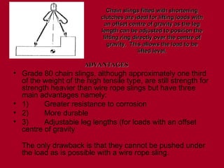
• Grade 80chain slings, although approximately one third
of the weight of the high tensile type, are still strength for
strength heavier than wire rope slings but have three
main advantages namely:
• 1) Greater resistance to corrosion
• 2) More durable
• 3) Adjustable leg lengths (for loads with an offset
centre of gravity
The only drawback is that they cannot be pushed under
the load as is possible with a wire rope sling.
Chain slings fitted with shortening
Chain slings fitted with shortening
clutches are ideal for lifting loads with
clutches are ideal for lifting loads with
an offset centre of gravity as the leg
an offset centre of gravity as the leg
length can be adjusted to position the
length can be adjusted to position the
lifting ring directly over the centre of
lifting ring directly over the centre of
gravity. This allows the load to be
gravity. This allows the load to be
lifted level.
lifted level.
ADVANTAGES
ADVANTAGES
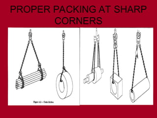
Use of chainslings
• The sling MUST be compatible with the lifting
appliance, it must also be compatible with the
load and any other lifting accessories in the
lifting arrangement, both in capacity and
physical size.
• The master link should seat correctly in the
hook of the appliance and articulate freely to
avoid deforming the link. In the same way, the
load, or its attachments, must seat in the sling
hooks, never on the point, and allow the hook
to align to avoid opening the throat or
deforming the hook.
118.
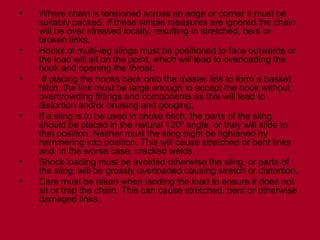
• Where chainis tensioned across an edge or corner it must be
suitably packed. If these simple measures are ignored the chain
will be over stressed locally, resulting in stretched, bent or
broken links.
• Hooks of multi-leg slings must be positioned to face outwards or
the load will sit on the point, which will lead to overloading the
hook and opening the throat.
• If placing the hooks back onto the master link to form a basket
hitch, the link must be large enough to accept the hook without
overcrowding fittings and components as this will lead to
distortion and/or bruising and gouging.
• If a sling is to be used in choke hitch, the parts of the sling
should be placed in the natural 120º angle, or they will slide to
that position. Neither must the sling bight be tightened by
hammering into position. This will cause stretched or bent links
and, in the worse case, cracked welds.
• Shock loading must be avoided otherwise the sling, or parts of
the sling, will be grossly overloaded causing stretch or distortion.
• Care must be taken when landing the load to ensure it does not
sit or trap the chain. This can cause stretched, bent or otherwise
damaged links.
119.
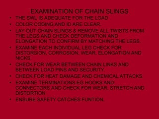
EXAMINATION OF CHAINSLINGS
• THE SWL IS ADEQUATE FOR THE LOAD
• COLOR CODING AND ID ARE CLEAR.
• LAY OUT CHAIN SLINGS & REMOVE ALL TWISTS FROM
THE LEGS AND CHECK DEFORMATION AND
ELONGATION TO CONFIRM BY MATCHING THE LEGS.
• EXAMINE EACH INDIVIDUAL LEG CHECK FOR
DISTORSION, CORROSION, WEAR, ELONGATION AND
NICKS.
• CHECK FOR WEAR BETWEEN CHAIN LINKS AND
BETWEEN LOAD PINS AND SECURITY.
• CHECK FOR HEAT DAMAGE AND CHEMICAL ATTACKS.
• EXAMINE TERMINATIONS.EG HOOKS AND
CONNECTORS AND CHECK FOR WEAR, STRETCH AND
DISTORTION
• ENSURE SAFETY CATCHES FUNTION.
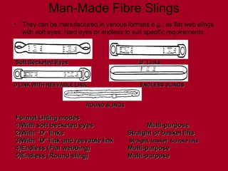
Man-Made Fibre Slings
•They can be manufactured in various formats e.g.: as flat web slings
with soft eyes, hard eyes or endless to suit specific requirements.
Soft Becketed Eyes
Soft Becketed Eyes “D” Links
“D” Links
D LINK WITH REEVABLE LINK
D LINK WITH REEVABLE LINK ENDLESS SLINGS
ENDLESS SLINGS
Format
Format Lifting modes
Lifting modes
1)With soft becketed eyes
1)With soft becketed eyes Multi-purpose
Multi-purpose
2)With “D” links
2)With “D” links Straight or basket lifts
Straight or basket lifts
3)With “D” link and reevable link
3)With “D” link and reevable link Straight, basket &choke lifts
Straight, basket &choke lifts
4)Endless (Flat webbing)
4)Endless (Flat webbing) Multi-purpose
Multi-purpose
5)Endless (Round sling)
5)Endless (Round sling) Multi-purpose
Multi-purpose
ROUND SLINGS
ROUND SLINGS
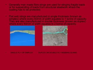
124.
• Generally manmade fibre slings are used for slinging fragile loads
or for suspending of loads from structural steelwork where the
coating has to be protected.
• Flat web slings are manufactured in single thickness (known as
simplex) where every 60mm of width equates to 1 tonne of capacity.
They are also manufactured in double thickness (known as duplex)
where every 60mm of width equates to 2 tonne of capacity.
• SINGLE PLY OR SIMPLEX DUPLEX OR DOUBLE PLY WEBBING SLINNG
• When describingyour requirement for man made fibre slings, the
length of flat web slings is always taken as bearing point to bearing
point. However, when describing endless sling 'length', you must
always quote the circumference
• The majority of man made fibre slings are made from polyester.
Here follows a guide to their resistance to various chemicals and
conditions liable to be found in a hostile environment:
Agent Resistance
• acid :good
• alkali :poor
• water / steam :good
• long term exposure to dry heat :excellent
• oxidising agents :excellent
• reducing agents :excellent
• solvents :good
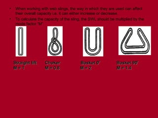
127.
• When workingwith web slings, the way in which they are used can affect
their overall capacity i.e. it can either increase or decrease.
• To calculate the capacity of the sling, the SWL should be multiplied by the
mode factor “M”
Straight lift
Straight lift Choker Basket 0
Choker Basket 0
Basket 90
Basket 90
M = 1
M = 1 M = 0.8
M = 0.8 M = 2
M = 2 M = 1.4
M = 1.4
128.
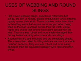
USES OF WEBBINGAND ROUND
SLINGS
• Flat woven webbing slings, sometimes referred to belt
slings, are soft to handle, pliable longitudinally whilst offering
rigidity across their width. These qualities make them ideal
for handling loads that require some support when being
lifted as the load is spread across their full width, unlike
ropes and chains that tend to have point contact with the
load. They are less robust and more easily damaged than
the equivalent capacity wire rope and chain slings.
• Roundslings are soft to handle and are completely pliable.
This makes them ideal for lifting delicate loads or loads with
polished surfaces. They are less robust and more easily
damaged than the equivalent capacity wire rope and chain
slings.
129.
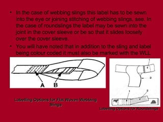
• In thecase of webbing slings this label has to be sewn
into the eye or joining stitching of webbing slings, see. In
the case of roundslings the label may be sewn into the
joint in the cover sleeve or be so that it slides loosely
over the cover sleeve.
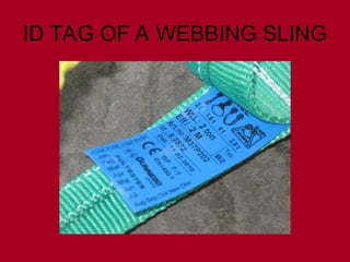
• You will have noted that in addition to the sling and label
being colour coded it must also be marked with the WLL
and the material.
Labelling Options for Flat Woven Webbing
Labelling Options for Flat Woven Webbing
Slings
Slings
Labelling Options for Roundslings
Labelling Options for Roundslings
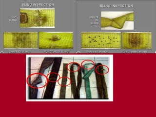
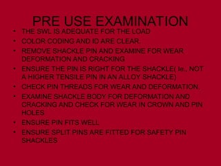
PRE USE EXAMINATION
•THE SWL IS ADEQUATE FOR THE LOAD
• COLOR CODING AND ID ARE CLEAR.
• CUTS, TEARS OR CHAFING
• BURST STICTCHING ESPECIALLY AROUND THE EYES.
• CHEMICAL DAMAGE
• ULTRAVIOLET DEGREDATION
• HEAT DAMAGE
• INGRESS OF FOREIGN BODIES INTO THE FIBRES LIKE
METAL PIECES ETC
• DISTORTION OR WEAR IN METAL EYES IF FITTED
132.
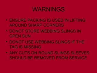
WARNINGS
• ENSURE PACKINGIS USED IN LIFTING
AROUND SHARP CORNERS
• DONOT STORE WEBBING SLINGS IN
OPEN SUN
• DONOT USE WEBBING SLINGS IF THE
TAG IS MISSING
• ANY CUTS ON ROUND SLINGS SLEEVES
SHOULD BE REMOVED FROM SERVICE
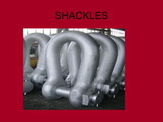
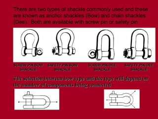
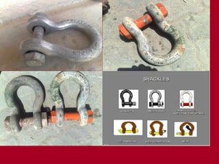
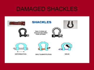
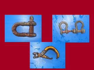
There are twotypes of shackle commonly used and these
are known as anchor shackles (Bow) and chain shackles
(Dee). Both are available with screw pin or safety pin
SCREW PIN BOW
SCREW PIN BOW
SHACKLE
SHACKLE
SAFETY PIN BOW
SAFETY PIN BOW
SHACKLE
SHACKLE
SCREW PIN DEE
SCREW PIN DEE
SHACKLE
SHACKLE
SAFETY PIN DEE
SAFETY PIN DEE
SHACKLE
SHACKLE
The selection between bow type and dee type will depend on
The selection between bow type and dee type will depend on
the number of components being connected
the number of components being connected
137.
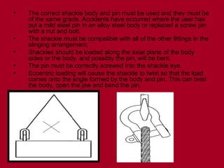
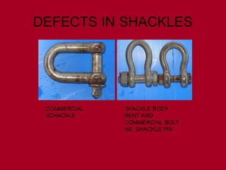
• The correctshackle body and pin must be used and they must be
of the same grade. Accidents have occurred where the user has
put a mild steel pin in an alloy steel body or replaced a screw pin
with a nut and bolt.
• The shackle must be compatible with all of the other fittings in the
slinging arrangement.
• Shackles should be loaded along the axial plane of the body
sides or the body, and possibly the pin, will be bent.
• The pin must be correctly screwed into the shackle eye.
• Eccentric loading will cause the shackle to twist so that the load
comes onto the angle formed by the body and pin. This can twist
the body, open the jaw and bend the pin.
138.
PRE USE EXAMINATION
•THE SWL IS ADEQUATE FOR THE LOAD
• COLOR CODING AND ID ARE CLEAR.
• REMOVE SHACKLE PIN AND EXAMINE FOR WEAR
DEFORMATION AND CRACKING
• ENSURE THE PIN IS RIGHT FOR THE SHACKLE( Ie., NOT
A HIGHER TENSILE PIN IN AN ALLOY SHACKLE)
• CHECK PIN THREADS FOR WEAR AND DEFORMATION.
• EXAMINE SHACKLE BODY FOR DEFORMATION AND
CRACKING AND CHECK FOR WEAR IN CROWN AND PIN
HOLES
• ENSURE PIN FITS WELL
• ENSURE SPLIT PINS ARE FITTED FOR SAFETY PIN
SHACKLES
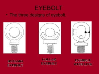
EYEBOLT
• The threedesigns of eyebolt.
DYNAMO
DYNAMO
EYEBOLT
EYEBOLT
COLLAR
COLLAR
EYEBOLT
EYEBOLT
EYEBOLT
EYEBOLT
WITH LINK
WITH LINK
144.
• The DynamoEyebolt is the most basic in
design and the most limited in use, being
suitable for axial lifting only. Effectively it is
a ring sitting on top of the shank and has
only a small collar. Although it is limited to
axial loads, the eye is large enough to
accept a hook of the same capacity.
• Dynamo Eyebolts get their name from the
historical use to which they are put, being
fitted by electric motor manufacturers to the
tapped hole over the balanced lifting point
of the motor.
145.
• Collar Eyeboltswere for many years considered to be the general purpose
eyebolt and indeed they remain so for many thread diameters. The eye is
larger than that of the Dynamo pattern and is blended to the collar in one
plane. However, the eye is not large enough for direct connection to a hook
and it is necessary to use a shackle for connection to other components.
• When used in pairs of the same capacity, the plane of the eye of each
eyebolt must not be inclined to the plane containing the axis of the two
eyebolts by more than 5°. In order not to over stress the shank, this
alignment may be achieved by use of shims up to a maximum of half of one
thread in thickness. A reduction in the maximum load that may be lifted is
necessary due to the angular loading. This is far more drastic than is
required with the Eyebolt with Link so that, although in axial loading size for
size Collar Eyebolts have a higher SWL, the capacity when subject to
angular loads is far lower.
146.
• EYEBOLT WITHLINK have a small, squat, eye which is blended
into the collar in all directions and a link is fitted to allow articulation
and connection with other lifting components. The link is designed to
accept a hook of the same capacity.
• Compared size for size with Collar Eyebolts, the SWL for axial load
is lower, in all other arrangements the SWL are relatively greater
than those of Collar Eyebolts when used in the same conditions.
Unlike the Collar Eyebolt, the load can be applied away from the
plane of the eye, as the link will articulate to align and the collar has
equal strength in all directions, making correct fitting easier.
• Provided that the angle of the load to the axis of the screw thread
does not exceed 15°, they may be loaded in any direction to the full
SWL rating. For greater angles, the load will decrease, however this
reduction is less drastic than with a Collar Eyebolt. In all respects
Eyebolts with Links can be considered the general purpose pattern
of eyebolt, to be used for lifting whenever the loading cannot be
confined to a single plane. They are however only produced in a
limited range of thread diameters, so limiting their application.
147.
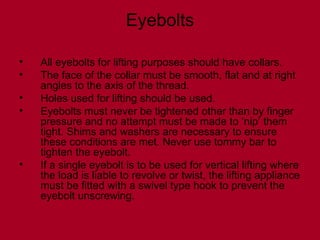
Eyebolts
• All eyeboltsfor lifting purposes should have collars.
• The face of the collar must be smooth, flat and at right
angles to the axis of the thread.
• Holes used for lifting should be used.
• Eyebolts must never be tightened other than by finger
pressure and no attempt must be made to ‘nip’ them
tight. Shims and washers are necessary to ensure
these conditions are met. Never use tommy bar to
tighten the eyebolt.
• If a single eyebolt is to be used for vertical lifting where
the load is liable to revolve or twist, the lifting appliance
must be fitted with a swivel type hook to prevent the
eyebolt unscrewing.
148.
Pre use examination
•THE SWL IS ADEQUATE FOR THE LOAD
• COLOR CODING AND ID ARE CLEAR.
• CHECK THREADS FOR WEAR, STRETCH, IMPACT
DAMAGE.
• THREADS SHOULD BE CONCENTRIC AND MESH WELL
• CHECK FOR DISTORTION, WEAR, CRACKS IN THE EYE
• CHECK SHANK AGAINST THE COLLAR FOR
STRAIGHTNESS.
• EXAMINE TAPPED HOLE.
Points to rememberbefore
lifting
• 1 All lifts shall be planned and risk assessed by a
competent person
• 2 All lifts will be supervised
• 3 All lifts will be carried out safely
• 4 Weight of load / cargo to be established and
appropriate equipment chosen prior to any lift
commencing
• 5 All personnel must keep out of any area where
they may be injured by a falling or shifting load
• 6 No personnel may stand below, return below, or
stand on top of a suspended load
152.
• 7 Allpersonnel involved in the lifting operation must
ensure a route of escape and never stand between a
load and a wall / container / barrier etc.
• 8 Prior to any lift, a toolbox talk must be undertaken
with all personnel involved
• 9 No lift will be undertaken without a plan being in
place, (either generic or unique plan depending on lifting /
handling operation)
• 10 Immediately a lift deviates from the plan or an
unexpected complication arises, the lifting operation must
be stopped, made safe and reassessed. All personnel
must remain clear of the lift until reassessment / re-
planning of the lift has been carried out
• 11 Lifting / handling operations must be undertaken
by a minimum of three competent people. A crane
operator, a banksman / signaller and a load handler /
slinger. Additional personnel may be used as required
153.
• 12 Thebanksman / signaller must be easily identifiable to
the crane operator from other personnel involved in the lifting
operation
• 13 The banksman / signaller must not touch the load. He
must ensure he has an unobstructed view of the load at all
times
• 14 The banksman / signaller must remain in
communication with the load handler / slinger and the crane
operator at all times
• 15 The banksman / signaller must keep the load handler /
slinger in sight during the lifting operation
• 16 The load handler / slinger must stand clear of a load
as it is lifted clear of the deck or ground, while it is being
landed, while slack is taken up and must confirm to the
banksman / slinger that he is clear
154.
• 17 Theload handler / slinger must not touch a load until
it is below his waist height as it is landed and must stand
clear of the load as it passes waist height during raising
• 18 The load handler / slinger must never attempt to
manually stop a swinging load
• 19 The load handler must be easily identifiable from the
banksman / signaller
• 20 For complicated and complex lifts a rigger must be
present as the competent supervisor of the lift
• 21 For complicated and complex lifts a written lift plan
and full risk assessment must be in place
• 22 Tandem lifts are automatically classed at least as a
complicated lift
• 23 Standard lifting equipment must not be used for man-
riding purposes except in exceptional circumstances
155.
Types of cranes
•Mobile Crane
• Overhead or gantry Crane
• Tower cranes
• Pedestal Crane
• Portal Crane
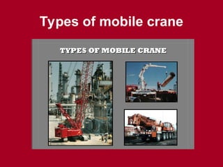
Mobile crane
• Roughterrain,
• All terrain cranes
• They have different
capacities based on
their duties
• On outriggers fully,
mid on no extension
• On rubber tires
• Flyjib duties
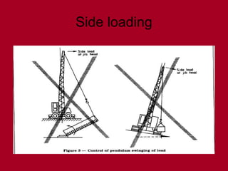
•Instability – unsecuredload, load capacity
exceeded, or ground not level or too soft
•Lack of communication - the point of
operation is a distance from the crane
operator or not in full view of the operator
•Lack of training
•Inadequate maintenance or inspection
How Do Accidents Occur?
162.
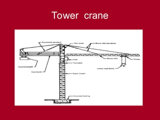
Definitions (crane model)
•Crane – Consists of a rotating structure for lifting and lowering
horizontally on rubber tires or crawler treads
• Hoist - Used to lift and lower load.
• Boom – An inclined spar, strut, or other long member supporting
the hoisting tackle
• Boom stops – A device used to limit the angle of the boom at its
highest position
• Brake – To slow or stop motion by friction or power
• Hook Block – Sheaves or grooved pulleys in a frame with hook,
eye and strap
• Radius –horizontal distance b/w center of slew and hook block.
• Boom angle-angle formed by the boom to the horizontal (ground
level)
• Jib – Extension attached to the boom point to provide added boom
length for lifting specified loads.
• Partlines / falls- no of ropes that the hook block is hanging off
from the boom tip.
163.
Definitions
Rated capacity: Maximumload that can be safely handled by a
crane at a specified position and under specified conditions
NOTE The rated capacity is the "safe working load".
Rated capacity indicator: A device that automatically provides,
within a specified tolerance, warning that the load is
approaching rated capacity, and another warning when rated
capacity is exceeded
NOTE Rated capacity indicators are also known as automatic
safe load indicators.
Rated capacity limiter: device that automatically prevents, within a
specified tolerance, motions that could increase risks, if the
Rated capacity is exceeded.
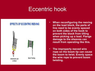
Eccentric hook
• Whenreconfiguring the reeving
on the load block, the parts of
line need to be evenly spaced
on both sides of the hook to
prevent the block from tilting
when picking up a load. Flange
damage to the sheaves can
result from operating like this.
• The improperly reeved wire
rope on the boom tip can cause
the boom to twist. Evenly space
the wire rope to prevent boom
twisting.
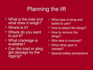
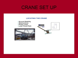
Planning the lift
•What is the load and
what does it weigh?
• Where is it?
• Where do you want
to put it?
• What craneage is
available?
• Can the load or sling
get damage by the
rigging?
• What type of sling and
tackle to use?
• How to attach the slings?
• How to remove the
slings?
• Who else is involved?
• What other gear is
needed?
• Special safety precautions
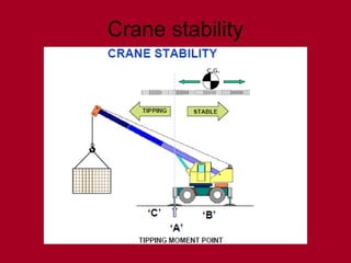
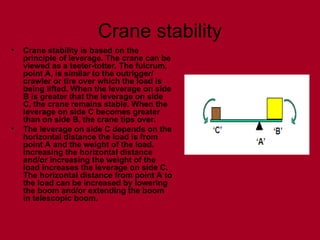
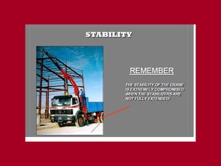
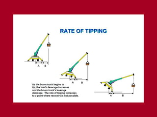
Crane stability
• Cranestability is based on the
principle of leverage. The crane can be
viewed as a teeter-totter. The fulcrum,
point A, is similar to the outrigger/
crawler or tire over which the load is
being lifted. When the leverage on side
B is greater that the leverage on side
C, the crane remains stable. When the
leverage on side C becomes greater
than on side B, the crane tips over.
• The leverage on side C depends on the
horizontal distance the load is from
point A and the weight of the load.
Increasing the horizontal distance
and/or increasing the weight of the
load increases the leverage on side C.
The horizontal distance from point A to
the load can be increased by lowering
the boom and/or extending the boom
in telescopic boom.
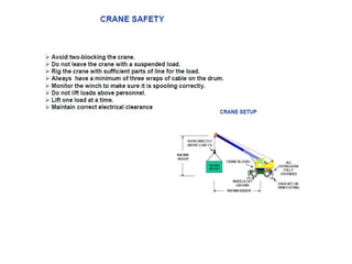
Crane safety
• Avoidtwo-blocking the crane.
• Do not leave the crane with a suspended load.
• Rig the crane with sufficient parts of line for the load.
• Always have a minimum of three wraps of cable on the
drum.
• Monitor the winch to make sure it is spooling correctly.
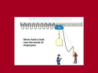
• Do not lift loads above personnel.
• Lift one load at a time.
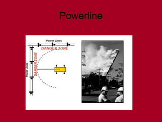
• Maintain correct electrical clearance.
193.
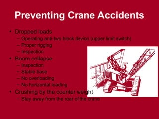
Preventing Crane Accidents
•Dropped loads
– Operating anti-two block device (upper limit switch)
– Proper rigging
– Inspection
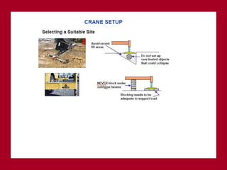
• Boom collapse
– Inspection
– Stable base
– No overloading
– No horizontal loading
• Crushing by the counter weight
– Stay away from the rear of the crane
#161 In addition to instability factors, communication, and training, some cranes are not maintained properly nor inspected regularly to ensure safe operation.
#162
OTHER DEFINITIONS
Boom angle indicator – An accessory device that measures the angle of boom base section centerline to horizontal
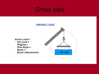
Load – The weight of the object being lifted including:
Load block and hook
Wire rope
Rigging
Boom attachments
Ancillary attachment
Outrigger – Support members attached to the crane’s carrier frame which are used to level the crane
Pendants – Stationary wire ropes used to support the boom
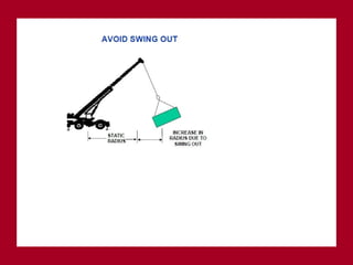
Radius – The horizontal distance from the axis of the rotation of the crane’s superstructure to the center of the suspended load
Superstructure – The rotating frame, gantry and boom or other operating equipment
Counter weight – Weights used for balancing loads and the weight of the crane in providing stability
Deck – The revolving superstructure or turntable bed.
Drum – The spool or cylindrical member around which cables are wound for raising and lowering loads