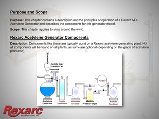
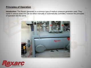
Since 1924, Rexarc has been recognized as the leader in high quality,
and high value industrial gas distribution systems ...There is no substitute!
Acetylene Generators – Part I
INTERNATIONAL, INC.
Table of Contents
• Calcium Carbide Skip (Transfer Cart)
• Calcium Carbide Hopper
• Hopper Gauge
• Vent Valves
• Equalizing Valve
• Control Switches
• Screw Feed
• Carbide Valve and Hydraulic System
• Pressure Transducers
• Temperature Safety Instrument
• Inlet Water Control Instrument
• Optional Low/Low and High/High Water Level
Alarms
• Inlet Water Control Valve
• Water Level Alarm
• Water Inlet Pressure Switch
• Water Pressure Gauge
• Residue/Lime Water Agitator
• Motor Control Center
• Automatic Lubrication Panel
• Water Level Valves
• Residue/Lime Water Drain Valve &
Control
• Flashback Arresters
• Safety Valves
• Plant Alarms
1. Purpose and Scope
2. Principles of Operation
3. Rexarc Acetylene Generator Components
INTERNATIONAL, INC.
Purpose and Scope
Purpose: This chapter contains a description and the principles of operation of a Rexarc ATX
Acetylene Generator and describes the components for this generator model.
Scope: This chapter applies to sites around the world.
Rexarc Acetylene Generator Components
Description: Components like these are typically found on a Rexarc acetylene generating plant. Not
all components will be found on all plants, as some are optional (depending on the grade of acetylene
produced).
INTERNATIONAL, INC.
Principles of Operation
Introduction: The Rexarc generator is a common type of medium pressure generator used. They
come in various sizes and can be either manually or automatically controlled, however the principles
of operation are the same.
INTERNATIONAL, INC.
Generator
The generator provides for the controlled reaction of carbide with water using either a single hopper
mounted at one end (smaller generators) or two hoppers mounted at either end of the generator
(larger generators) that are used alternatively. The two hoppers allow continuous acetylene
production, without shutting down to recharge the hoppers.
When the pressure inside the generator drops, a carbide screw feed conveys carbide to the
generator tank from the hoppers. The generator is designed for carbide sized between 1-2 inches
(25-50 mm) and a dust component of less than 15%.
As the calcium carbide reacts with the water in the generator, heat, lime and acetylene gas is
produced. The gas produced causes the pressure in the generator to rise and the screw feed to stop
at a preset pressure closing the carbide feed valve and stopping the flow of calcium carbide into the
generator.
Acetylene gas is drawn off the generator by the compressor causing the pressure to
drop and a low pressure setting on the transducer starts the screw feed, feeding more
calcium carbide into the generator causing the gas pressure to rise.
INTERNATIONAL, INC.
Generator Controls
If the generator is automatically controlled, water is added to the generator through spray nozzles to
control the heat generated during the reaction, maintaining a set operating temperature.
Note:
1. Smaller capacity generators have no automatically controlled water injection system. Water must
be drained from this type of generator and refilled each time a new charge is required.
When the rising water reaches a certain level a diaphragm control valve automatically opens the
drain valve and drains off lime slurry, closing when the level returns to normal.
2. If the water level rises above the high water level inside the generator, an alarm will sound and no
further water can be added until the level has been returned to normal.
A low water alarm is also activated if the lime slurry falls below a set level in the generator.
INTERNATIONAL, INC.
Calcium Carbide Skip (Transfer Cart)
Description: A skip/transfer cart is used to transport calcium carbide from the drum opening area or
the carbide container staging stand to the generator hopper. This cart is matched to the size of the
hopper capacity of the generator.
CAUTION: When calcium carbide vessels are emptied into a skip/transfer cart in preparation for
generator recharging care must be taken to ensure that:
• Calcium carbide is not loaded into the skip/cart until required to limit exposure to atmospheric
moisture.
• Calcium carbide can be covered and purged if necessary in the event of hoist failure or emergency
generator shut-down.
• Loading should not proceed without grounding the skip/cart and the carbide container on the
staging stand.
INTERNATIONAL, INC.
Calcium Carbide Hopper
Description: Calcium carbide is held in the hopper(s) ready to be fed into the generator body.
Generators can either have one hopper, which means the production of acetylene gas must be halted
when it is empty and requires recharging, or have two hoppers, one mounted at either end of the
generator tank. These are used alternatively to provide continuous acetylene production.
The hoppers come standard with a relief valve to keep from being over pressurized.
The hoppers are available in 300 pounds (136kg), 600 pounds (272kg), 1200 pounds (544kg), 2500
pounds (1134kg) and 5000 pounds (2267kg).
INTERNATIONAL, INC.
Hopper Gauge
Description: A hopper gauge shows the acetylene pressure in the hopper (during recharging this will
be slightly lower than the generator tank pressure). During normal operation the hopper pressure and
generator pressure should be equal.
This gauge is used to indicate pressure when recharging the hopper, to indicate when pressure is
vented to atmosphere and when equalizing the hopper and generator tank pressure after recharging.
INTERNATIONAL, INC.
Vent Valves
Description: These are used to manually vent the carbide hopper of:
• Acetylene before charging
• Nitrogen that has been used to purge the hopper before the hopper lid is removed
• Nitrogen and air after the hopper has been purged after charging
Equalizing Valve
Description: This valve is used for equalizing pressure in the hoppers after carbide charging. It is
closed during normal operation and open only during the pressure equalizing process.
INTERNATIONAL, INC.
Control Switches
Description: If there are two hoppers installed, switches are mounted near the generator tank to
control the operation of the hoppers.
When the operating hopper runs out of carbide, the tank pressure drops to a predetermined pressure
and actuates the low-pressure mercoid switch 5-6 PSI (35-42 kPa) to automatically start the second
hopper.
The empty hopper is then turned off and recharged.
When the operator pushes the high mercoid button the operating pressure is raised from the 5-6 PSI
(35-42 kPa) range to the 7-8 PSI (50-64 kPa) operating range.
INTERNATIONAL, INC.
Screw Feed
Description: A screw feed pushes calcium carbide towards the carbide valve from the hopper. It is
electrically driven and is controlled by mercoid switches which start it when the generator pressure
falls below a set pressure and stops it when the pressure rises to a preset level.
Carbide Valve and Hydraulic System
Description: The carbide valve has a soft rubber seat that is held against the screw feed opening by a
spring.
When the screw feed starts, a hydraulic gear pump builds pressure in the hydraulic cylinder, which is
connected to the carbide valve.
The hydraulic cylinder overcomes the pressure of the spring and opens the carbide valve allowing
carbide to enter the generator tank.
When the screw feed stops hydraulic pressure is lost and the spring closes the carbide valve.
A gauge is fitted to the hydraulic system, which registers the hydraulic pressure, and a safety valve
protects the cylinder from over pressure.
INTERNATIONAL, INC.
Pressure Transducers
Description: These are external switches fitted to the
generator. The high pressure switch is set at 7-8 psig (50-64
kPa) and the low pressure mercoid switch are set at 5-6 psig
(35-42 kPa). The set pressure is done on a screen on the motor
control center
They are used to operate the screw feed and change over from
empty to full hoppers.
The screen has been designed so that multiple 4-20ma
pressure transducer ranges can be used. All that is needed
is to enter the correct range of the transducer.
INTERNATIONAL, INC.
Temperature Safety Instrument
Description: This instrument measures the temperature of the
acetylene in the generator tank and closes the alarm circuit when the
temperature reaches a set point. Normally it is set 10°F (5. 6°C)
above the inlet water control instrument temperature setting using the
password protected set screen. It must never be set above the
maximum operating temperature of the generator (176°F or 80°C).
Inlet Water Control Instrument
Description: This instrument measures the temperature of the
acetylene in the generator tank and opens the water inlet valve when
the temperature reaches the set point. The temperature setting is
password protected and has both an on and off setting. A high
temperature warning is activated when the generator temperature
reaches 10°F above the water inlet set point. Water is added by
temperature and whenever the carbide feeders are running.
INTERNATIONAL, INC.
Optional Low/Low and High/High Water Level Alarms
Description: Separate controls on the opposite end of the generator for the high/high and low/low
alarms. These are in addition to the standard high and low water level alarms.
INTERNATIONAL, INC.
Inlet Water Control Valve
Description: This air operated valve opens to allow water to enter the generator through spray
nozzles when the generator tank temperature rises to the set point on the water control instrument (B).
A spring closes the valve when the air supply to it is off.
The water supply has a meter fitted to measure the amount of water supplied to the generator. By
adjusting the water control instrument (B) to either increase or decrease the water supplied to the
generator the correct carbide to water ratio (approximately 8:1 by weight) can be maintained.
INTERNATIONAL, INC.
Water Level Alarm
Description: When the water level varies from the normal operating level (higher or lower) a proximity
switch comes on (orange light). This signal to the motor control center causes the generator actuated
ball valve to open and a lowering of the slurry level to happen. The generator must only be operated
when the water is at the correct operational level.
Click here for Rexarc Acetylene Generator – Part II

Rexarc Acetylene Generators - Part I

  • 1.
    Since 1924, Rexarchas been recognized as the leader in high quality, and high value industrial gas distribution systems ...There is no substitute! Acetylene Generators – Part I
  • 2.
    INTERNATIONAL, INC. Table ofContents • Calcium Carbide Skip (Transfer Cart) • Calcium Carbide Hopper • Hopper Gauge • Vent Valves • Equalizing Valve • Control Switches • Screw Feed • Carbide Valve and Hydraulic System • Pressure Transducers • Temperature Safety Instrument • Inlet Water Control Instrument • Optional Low/Low and High/High Water Level Alarms • Inlet Water Control Valve • Water Level Alarm • Water Inlet Pressure Switch • Water Pressure Gauge • Residue/Lime Water Agitator • Motor Control Center • Automatic Lubrication Panel • Water Level Valves • Residue/Lime Water Drain Valve & Control • Flashback Arresters • Safety Valves • Plant Alarms 1. Purpose and Scope 2. Principles of Operation 3. Rexarc Acetylene Generator Components
  • 3.
    INTERNATIONAL, INC. Purpose andScope Purpose: This chapter contains a description and the principles of operation of a Rexarc ATX Acetylene Generator and describes the components for this generator model. Scope: This chapter applies to sites around the world. Rexarc Acetylene Generator Components Description: Components like these are typically found on a Rexarc acetylene generating plant. Not all components will be found on all plants, as some are optional (depending on the grade of acetylene produced).
  • 4.
    INTERNATIONAL, INC. Principles ofOperation Introduction: The Rexarc generator is a common type of medium pressure generator used. They come in various sizes and can be either manually or automatically controlled, however the principles of operation are the same.
  • 5.
    INTERNATIONAL, INC. Generator The generatorprovides for the controlled reaction of carbide with water using either a single hopper mounted at one end (smaller generators) or two hoppers mounted at either end of the generator (larger generators) that are used alternatively. The two hoppers allow continuous acetylene production, without shutting down to recharge the hoppers. When the pressure inside the generator drops, a carbide screw feed conveys carbide to the generator tank from the hoppers. The generator is designed for carbide sized between 1-2 inches (25-50 mm) and a dust component of less than 15%. As the calcium carbide reacts with the water in the generator, heat, lime and acetylene gas is produced. The gas produced causes the pressure in the generator to rise and the screw feed to stop at a preset pressure closing the carbide feed valve and stopping the flow of calcium carbide into the generator. Acetylene gas is drawn off the generator by the compressor causing the pressure to drop and a low pressure setting on the transducer starts the screw feed, feeding more calcium carbide into the generator causing the gas pressure to rise.
  • 6.
    INTERNATIONAL, INC. Generator Controls Ifthe generator is automatically controlled, water is added to the generator through spray nozzles to control the heat generated during the reaction, maintaining a set operating temperature. Note: 1. Smaller capacity generators have no automatically controlled water injection system. Water must be drained from this type of generator and refilled each time a new charge is required. When the rising water reaches a certain level a diaphragm control valve automatically opens the drain valve and drains off lime slurry, closing when the level returns to normal. 2. If the water level rises above the high water level inside the generator, an alarm will sound and no further water can be added until the level has been returned to normal. A low water alarm is also activated if the lime slurry falls below a set level in the generator.
  • 7.
    INTERNATIONAL, INC. Calcium CarbideSkip (Transfer Cart) Description: A skip/transfer cart is used to transport calcium carbide from the drum opening area or the carbide container staging stand to the generator hopper. This cart is matched to the size of the hopper capacity of the generator. CAUTION: When calcium carbide vessels are emptied into a skip/transfer cart in preparation for generator recharging care must be taken to ensure that: • Calcium carbide is not loaded into the skip/cart until required to limit exposure to atmospheric moisture. • Calcium carbide can be covered and purged if necessary in the event of hoist failure or emergency generator shut-down. • Loading should not proceed without grounding the skip/cart and the carbide container on the staging stand.
  • 8.
    INTERNATIONAL, INC. Calcium CarbideHopper Description: Calcium carbide is held in the hopper(s) ready to be fed into the generator body. Generators can either have one hopper, which means the production of acetylene gas must be halted when it is empty and requires recharging, or have two hoppers, one mounted at either end of the generator tank. These are used alternatively to provide continuous acetylene production. The hoppers come standard with a relief valve to keep from being over pressurized. The hoppers are available in 300 pounds (136kg), 600 pounds (272kg), 1200 pounds (544kg), 2500 pounds (1134kg) and 5000 pounds (2267kg).
  • 9.
    INTERNATIONAL, INC. Hopper Gauge Description:A hopper gauge shows the acetylene pressure in the hopper (during recharging this will be slightly lower than the generator tank pressure). During normal operation the hopper pressure and generator pressure should be equal. This gauge is used to indicate pressure when recharging the hopper, to indicate when pressure is vented to atmosphere and when equalizing the hopper and generator tank pressure after recharging.
  • 10.
    INTERNATIONAL, INC. Vent Valves Description:These are used to manually vent the carbide hopper of: • Acetylene before charging • Nitrogen that has been used to purge the hopper before the hopper lid is removed • Nitrogen and air after the hopper has been purged after charging Equalizing Valve Description: This valve is used for equalizing pressure in the hoppers after carbide charging. It is closed during normal operation and open only during the pressure equalizing process.
  • 11.
    INTERNATIONAL, INC. Control Switches Description:If there are two hoppers installed, switches are mounted near the generator tank to control the operation of the hoppers. When the operating hopper runs out of carbide, the tank pressure drops to a predetermined pressure and actuates the low-pressure mercoid switch 5-6 PSI (35-42 kPa) to automatically start the second hopper. The empty hopper is then turned off and recharged. When the operator pushes the high mercoid button the operating pressure is raised from the 5-6 PSI (35-42 kPa) range to the 7-8 PSI (50-64 kPa) operating range.
  • 12.
    INTERNATIONAL, INC. Screw Feed Description:A screw feed pushes calcium carbide towards the carbide valve from the hopper. It is electrically driven and is controlled by mercoid switches which start it when the generator pressure falls below a set pressure and stops it when the pressure rises to a preset level. Carbide Valve and Hydraulic System Description: The carbide valve has a soft rubber seat that is held against the screw feed opening by a spring. When the screw feed starts, a hydraulic gear pump builds pressure in the hydraulic cylinder, which is connected to the carbide valve. The hydraulic cylinder overcomes the pressure of the spring and opens the carbide valve allowing carbide to enter the generator tank. When the screw feed stops hydraulic pressure is lost and the spring closes the carbide valve. A gauge is fitted to the hydraulic system, which registers the hydraulic pressure, and a safety valve protects the cylinder from over pressure.
  • 13.
    INTERNATIONAL, INC. Pressure Transducers Description:These are external switches fitted to the generator. The high pressure switch is set at 7-8 psig (50-64 kPa) and the low pressure mercoid switch are set at 5-6 psig (35-42 kPa). The set pressure is done on a screen on the motor control center They are used to operate the screw feed and change over from empty to full hoppers. The screen has been designed so that multiple 4-20ma pressure transducer ranges can be used. All that is needed is to enter the correct range of the transducer.
  • 14.
    INTERNATIONAL, INC. Temperature SafetyInstrument Description: This instrument measures the temperature of the acetylene in the generator tank and closes the alarm circuit when the temperature reaches a set point. Normally it is set 10°F (5. 6°C) above the inlet water control instrument temperature setting using the password protected set screen. It must never be set above the maximum operating temperature of the generator (176°F or 80°C). Inlet Water Control Instrument Description: This instrument measures the temperature of the acetylene in the generator tank and opens the water inlet valve when the temperature reaches the set point. The temperature setting is password protected and has both an on and off setting. A high temperature warning is activated when the generator temperature reaches 10°F above the water inlet set point. Water is added by temperature and whenever the carbide feeders are running.
  • 15.
    INTERNATIONAL, INC. Optional Low/Lowand High/High Water Level Alarms Description: Separate controls on the opposite end of the generator for the high/high and low/low alarms. These are in addition to the standard high and low water level alarms.
  • 16.
    INTERNATIONAL, INC. Inlet WaterControl Valve Description: This air operated valve opens to allow water to enter the generator through spray nozzles when the generator tank temperature rises to the set point on the water control instrument (B). A spring closes the valve when the air supply to it is off. The water supply has a meter fitted to measure the amount of water supplied to the generator. By adjusting the water control instrument (B) to either increase or decrease the water supplied to the generator the correct carbide to water ratio (approximately 8:1 by weight) can be maintained.
  • 17.
    INTERNATIONAL, INC. Water LevelAlarm Description: When the water level varies from the normal operating level (higher or lower) a proximity switch comes on (orange light). This signal to the motor control center causes the generator actuated ball valve to open and a lowering of the slurry level to happen. The generator must only be operated when the water is at the correct operational level. Click here for Rexarc Acetylene Generator – Part II