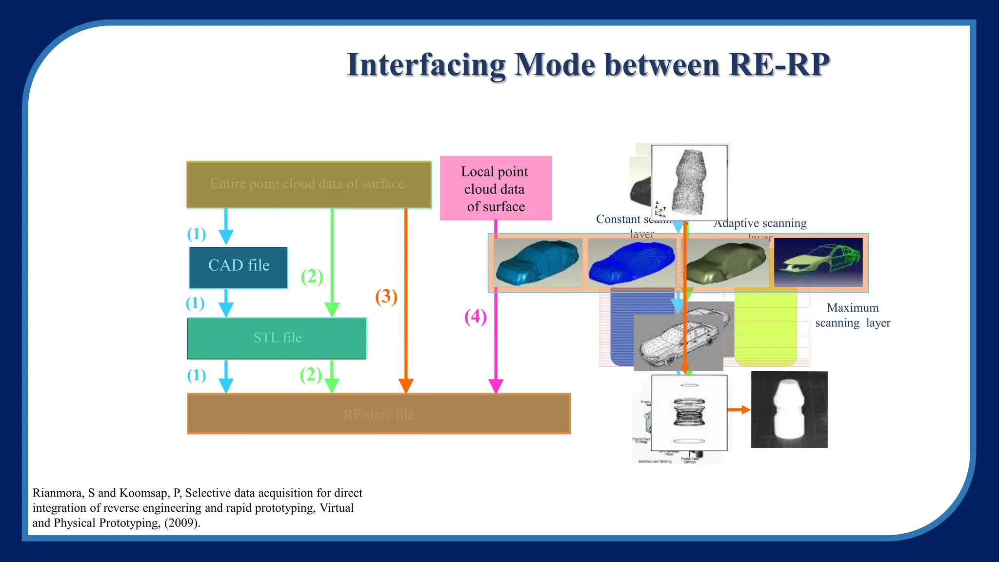
(1) Reverse engineering uses point data from physical objects to reconstruct 3D CAD models. It is useful when the original design files are unavailable or a product requires frequent changes.
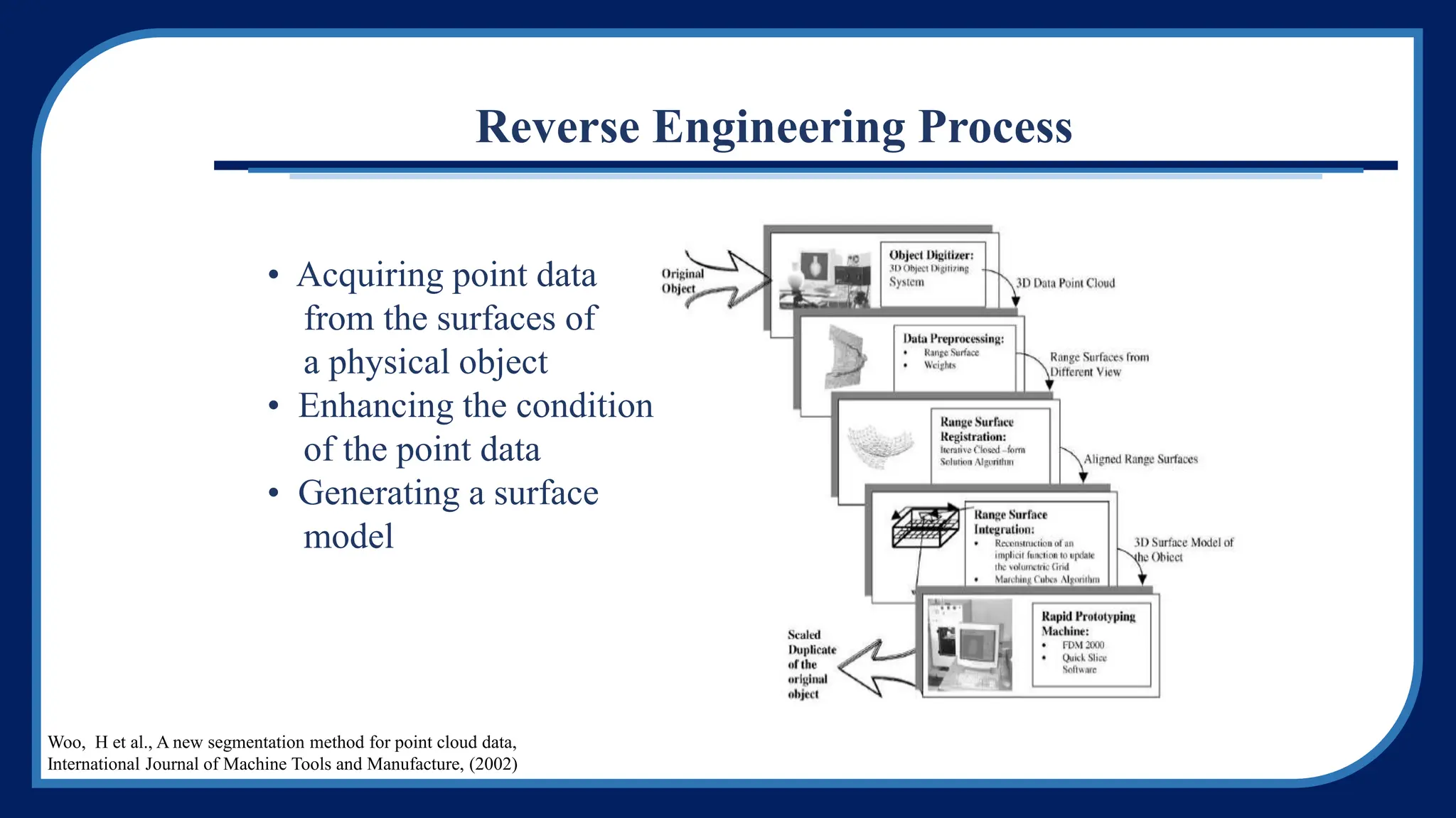
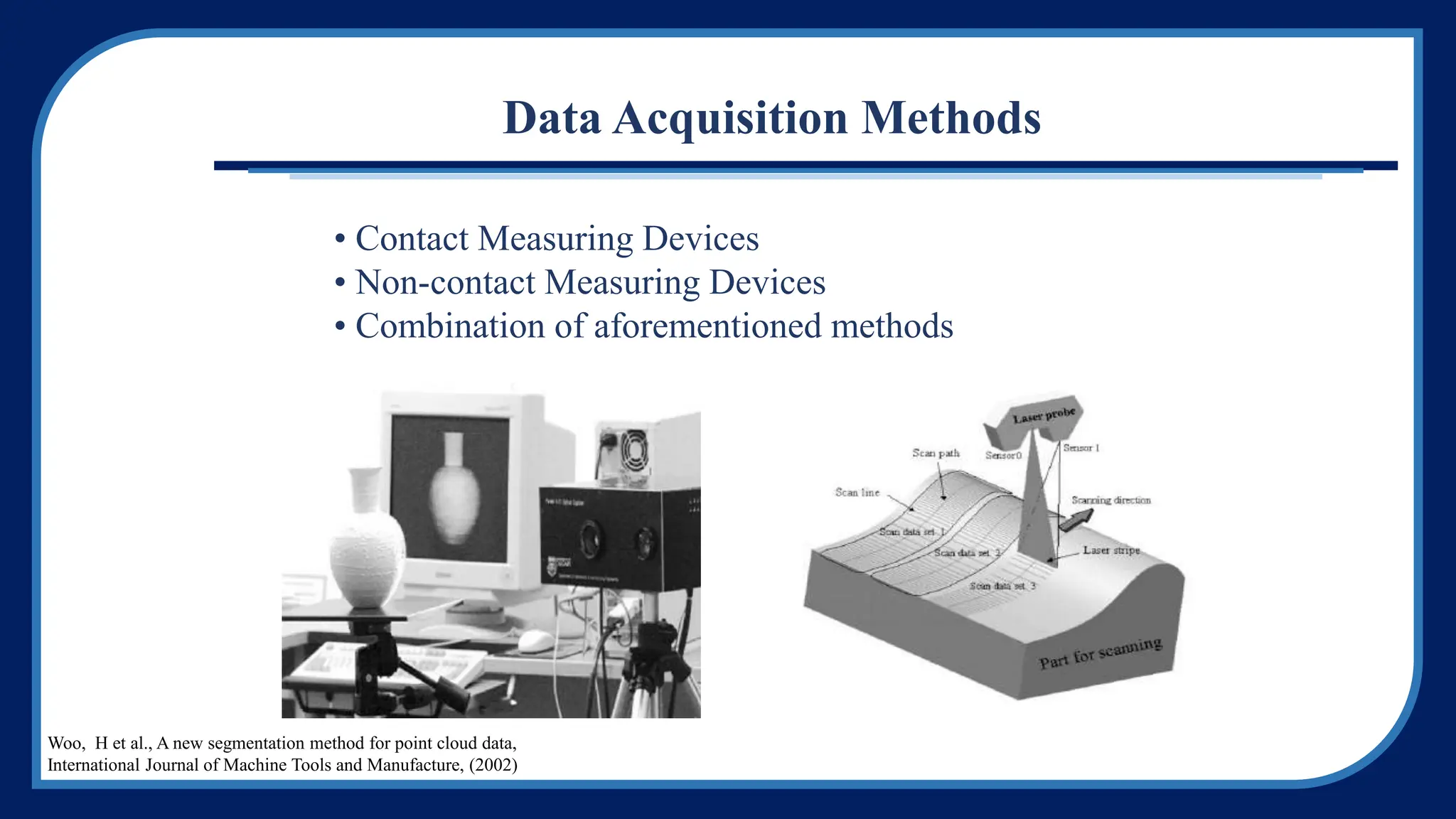
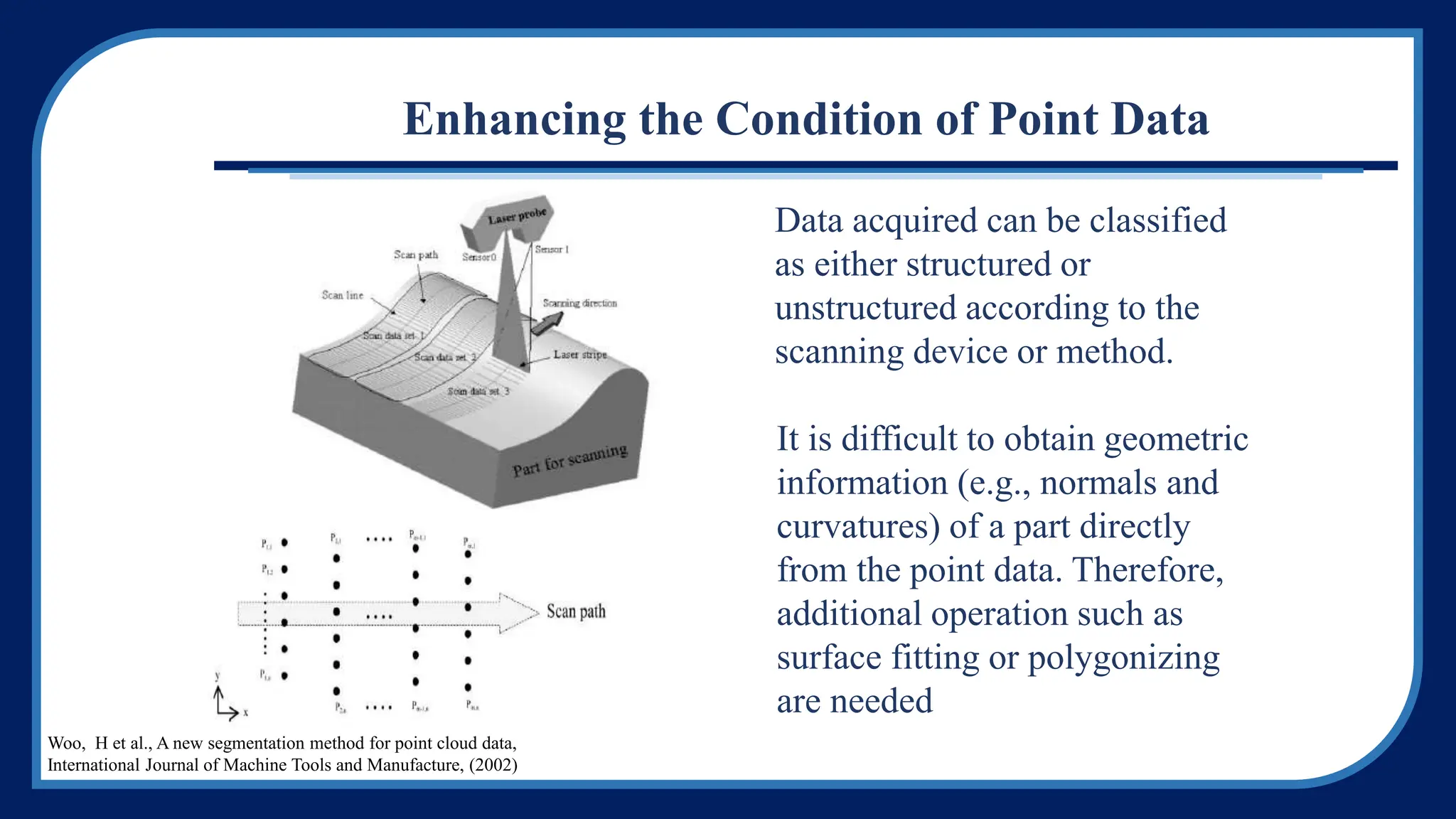
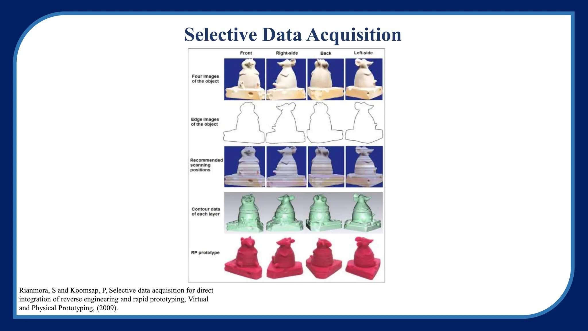
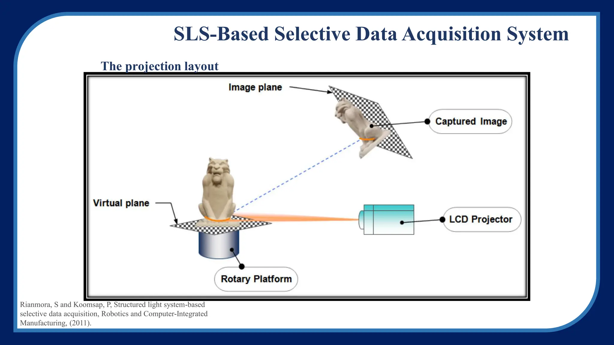
(2) The reverse engineering process involves acquiring point data, enhancing the data quality, and generating a surface model. Point data can be acquired through contact or non-contact methods and segmented to separate surfaces.
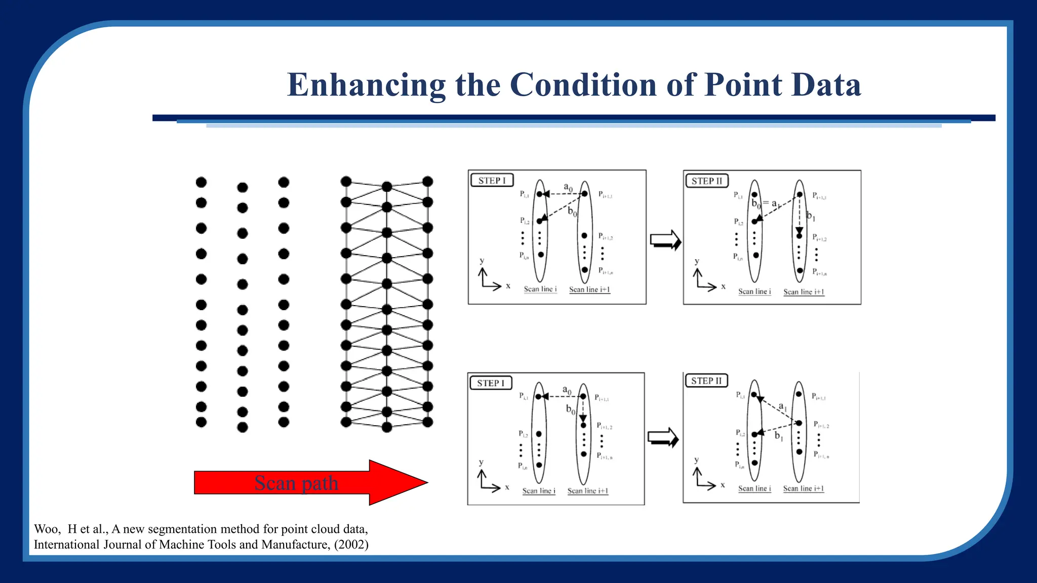
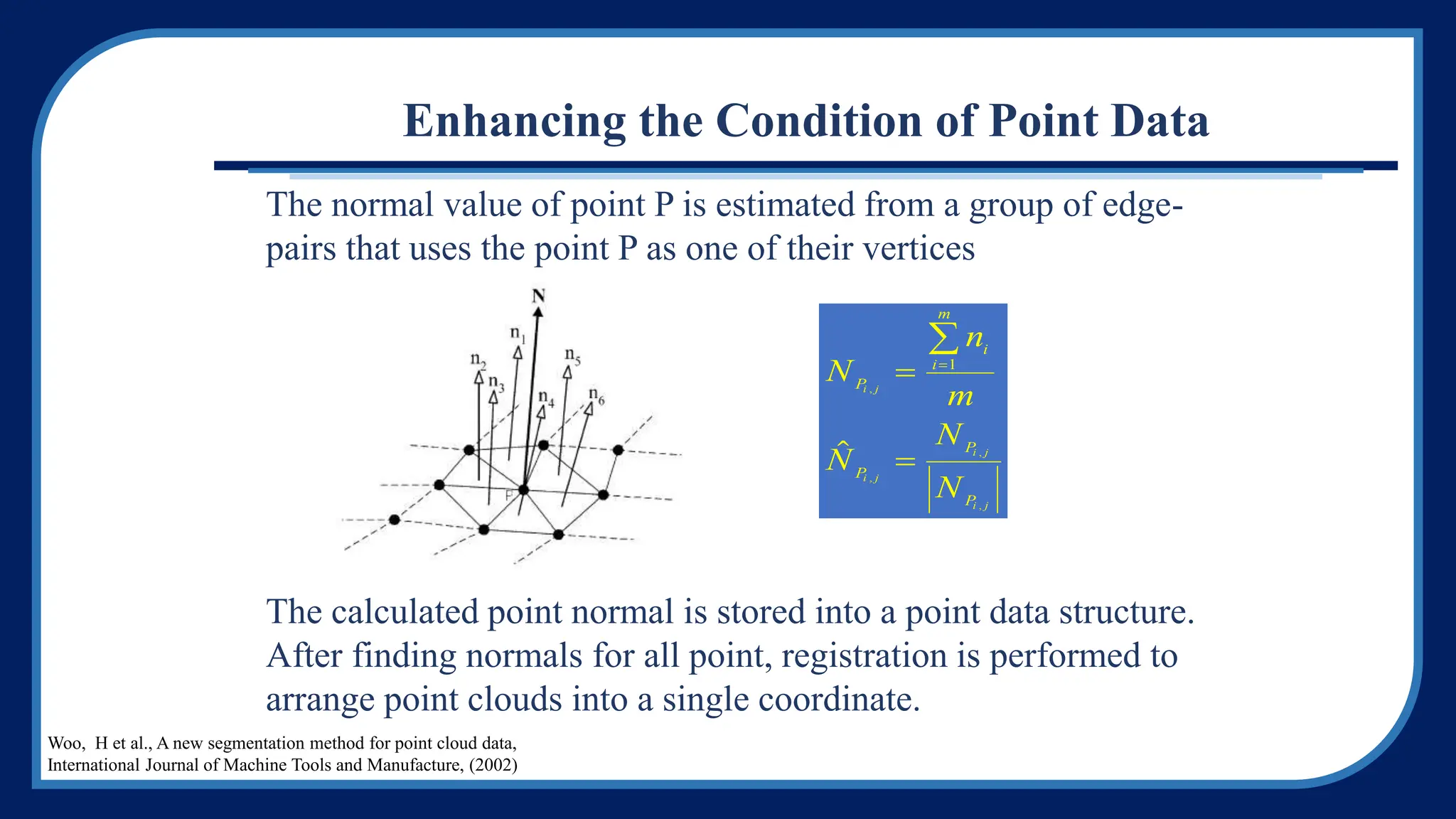
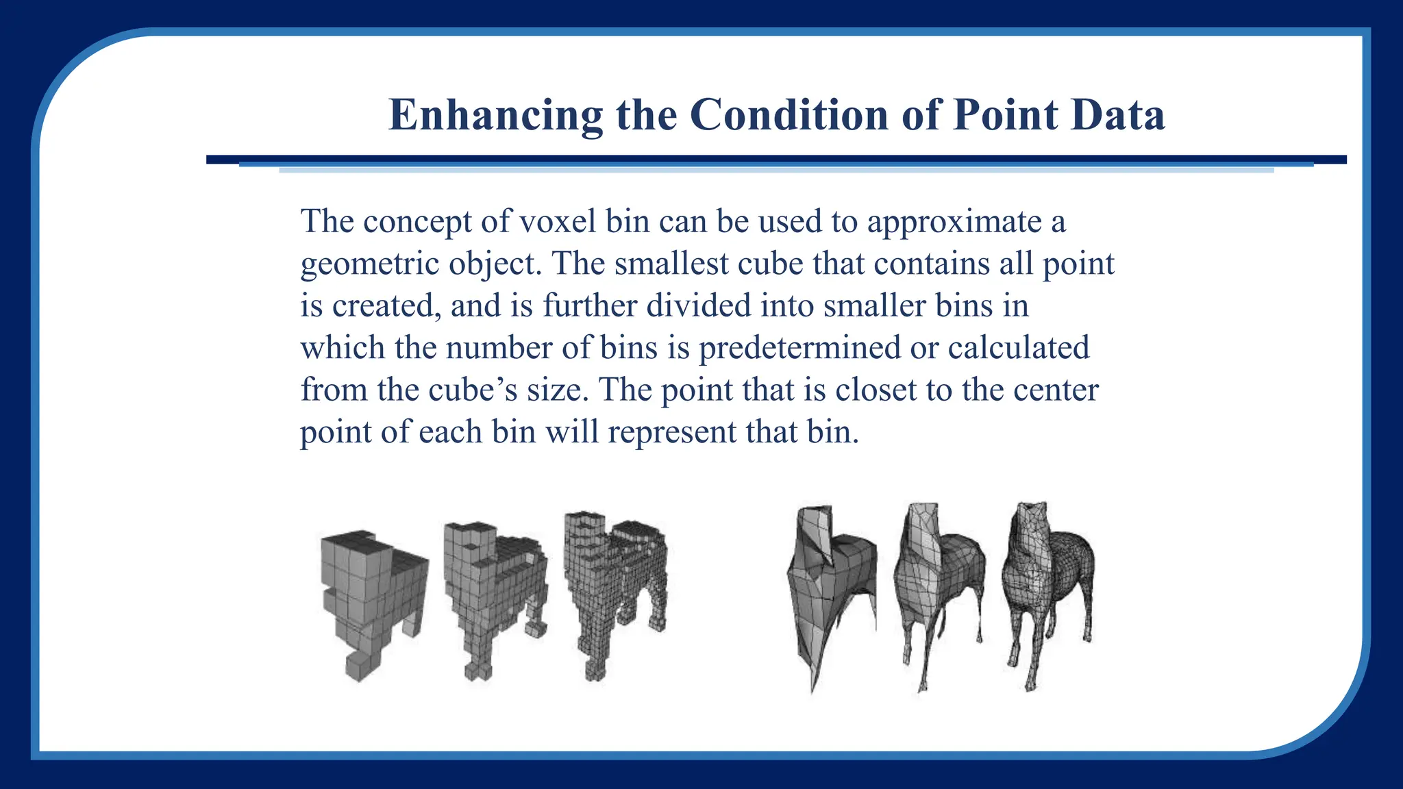
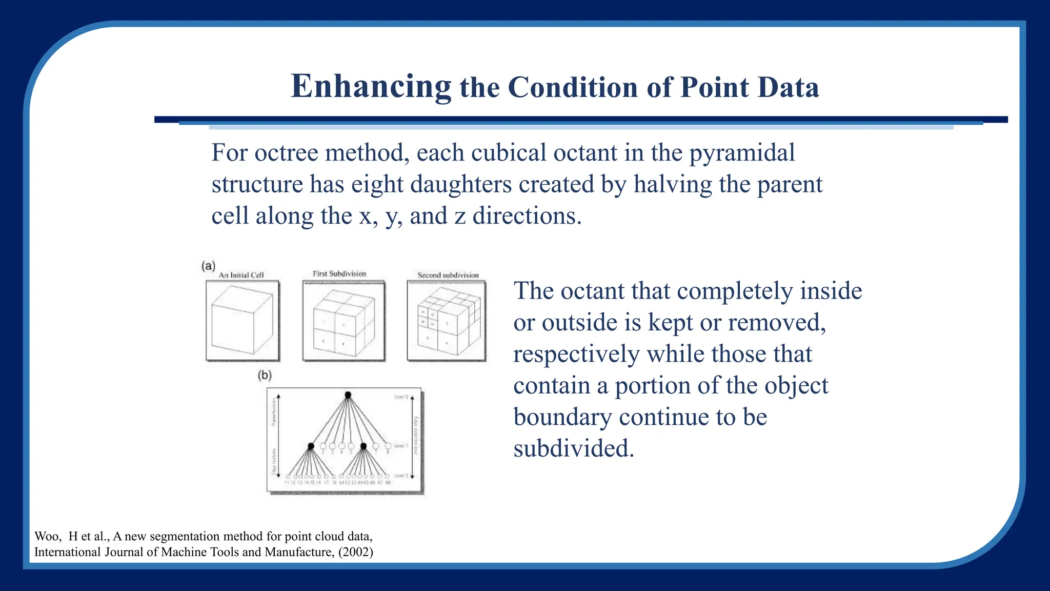
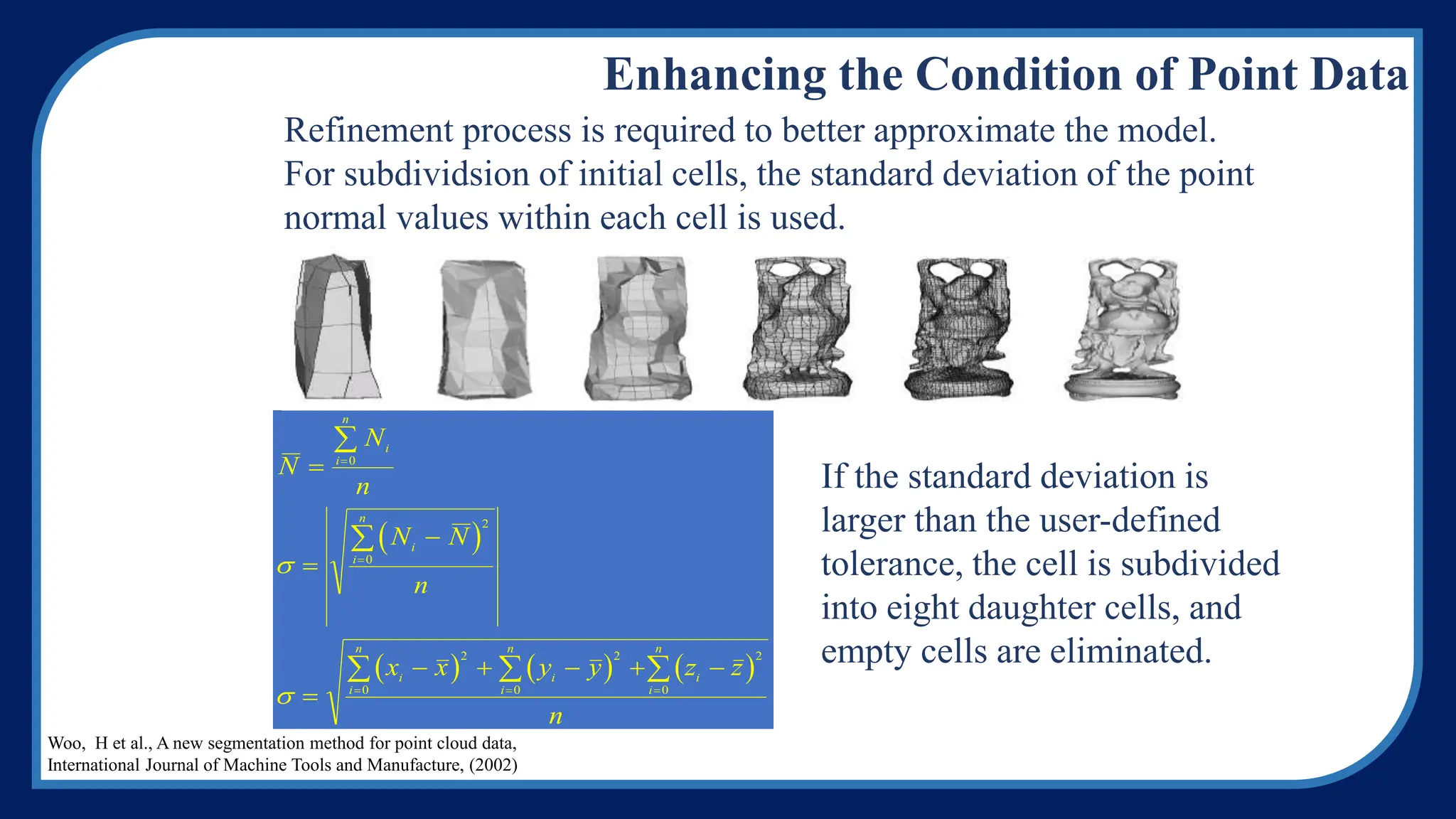
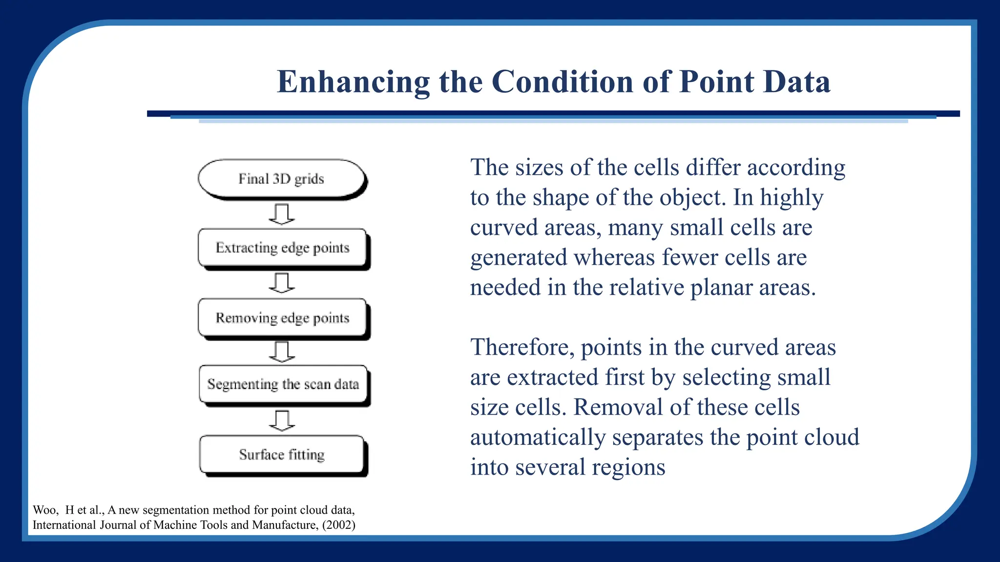
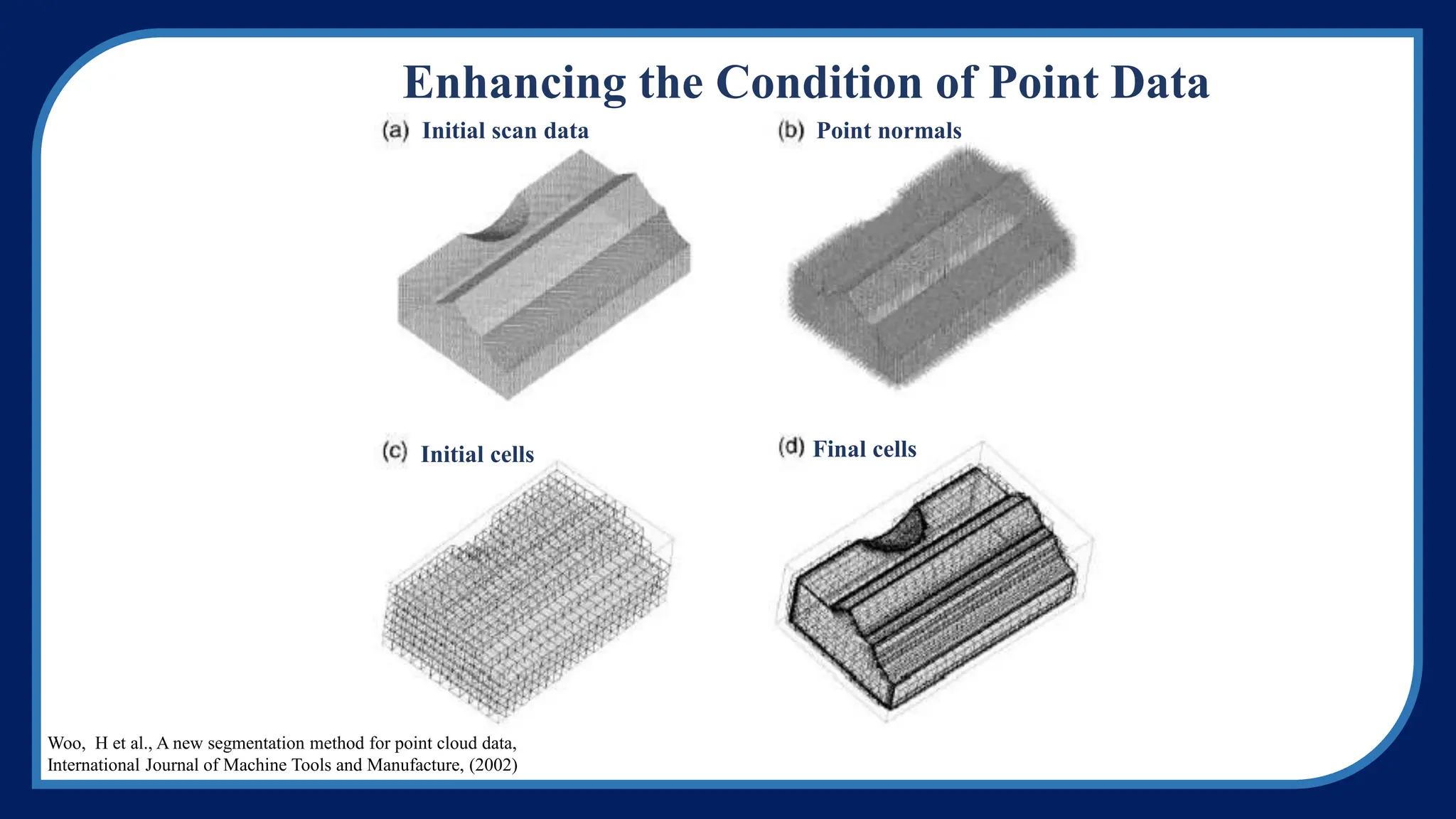
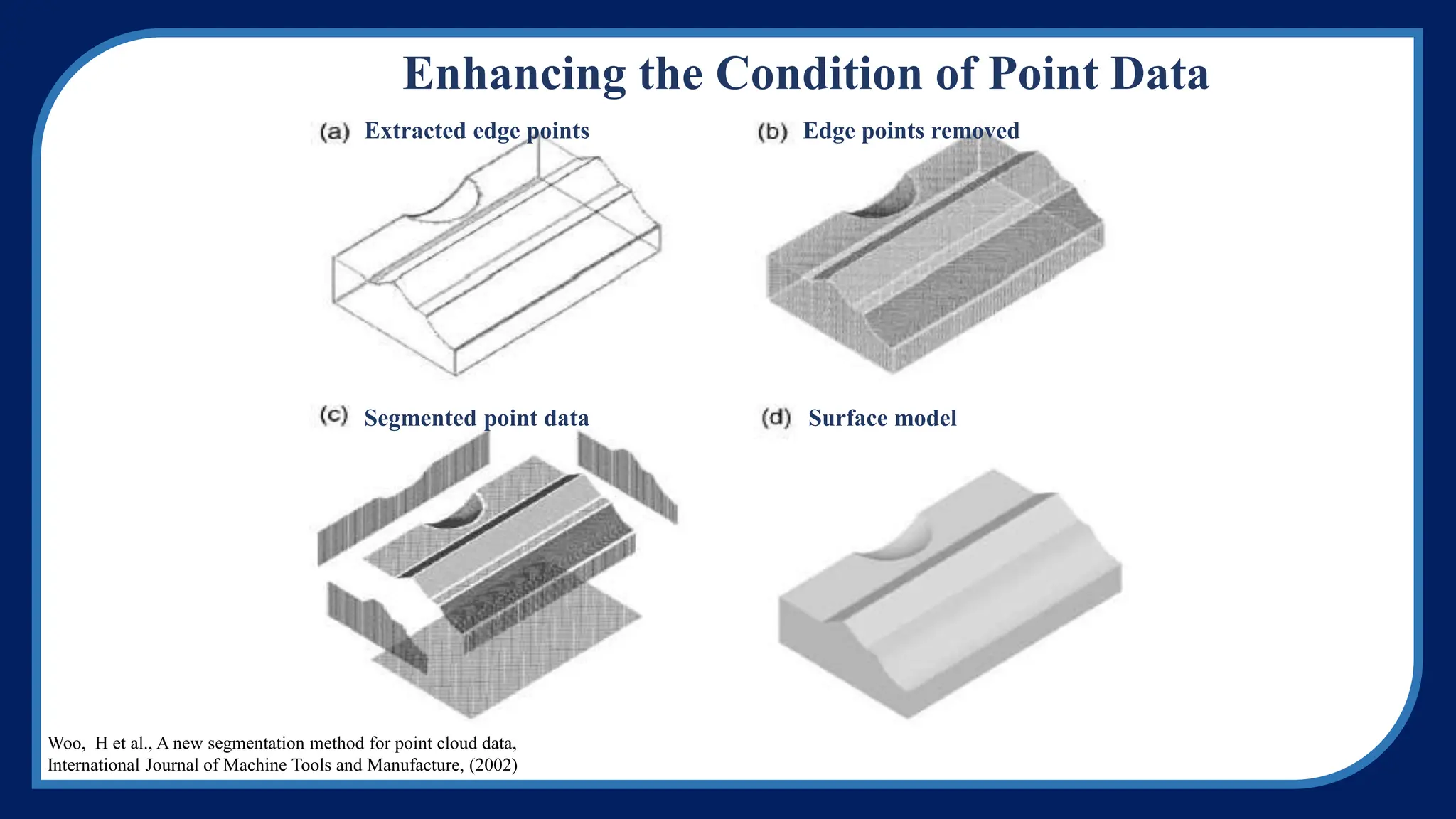
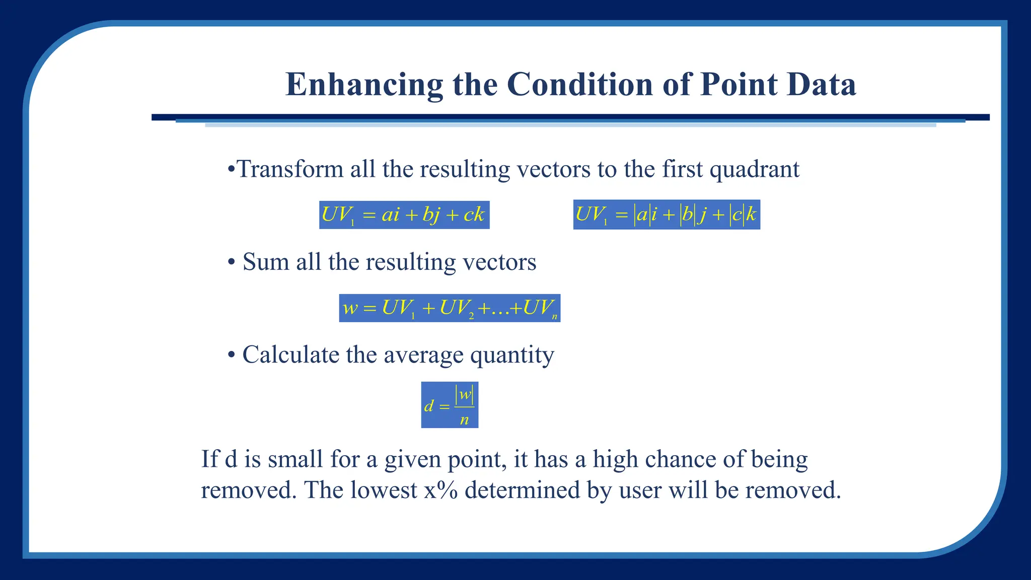
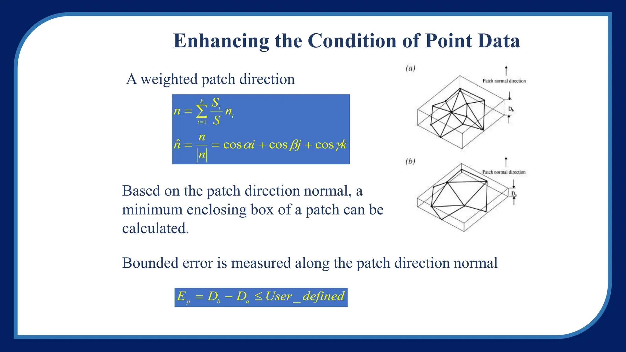
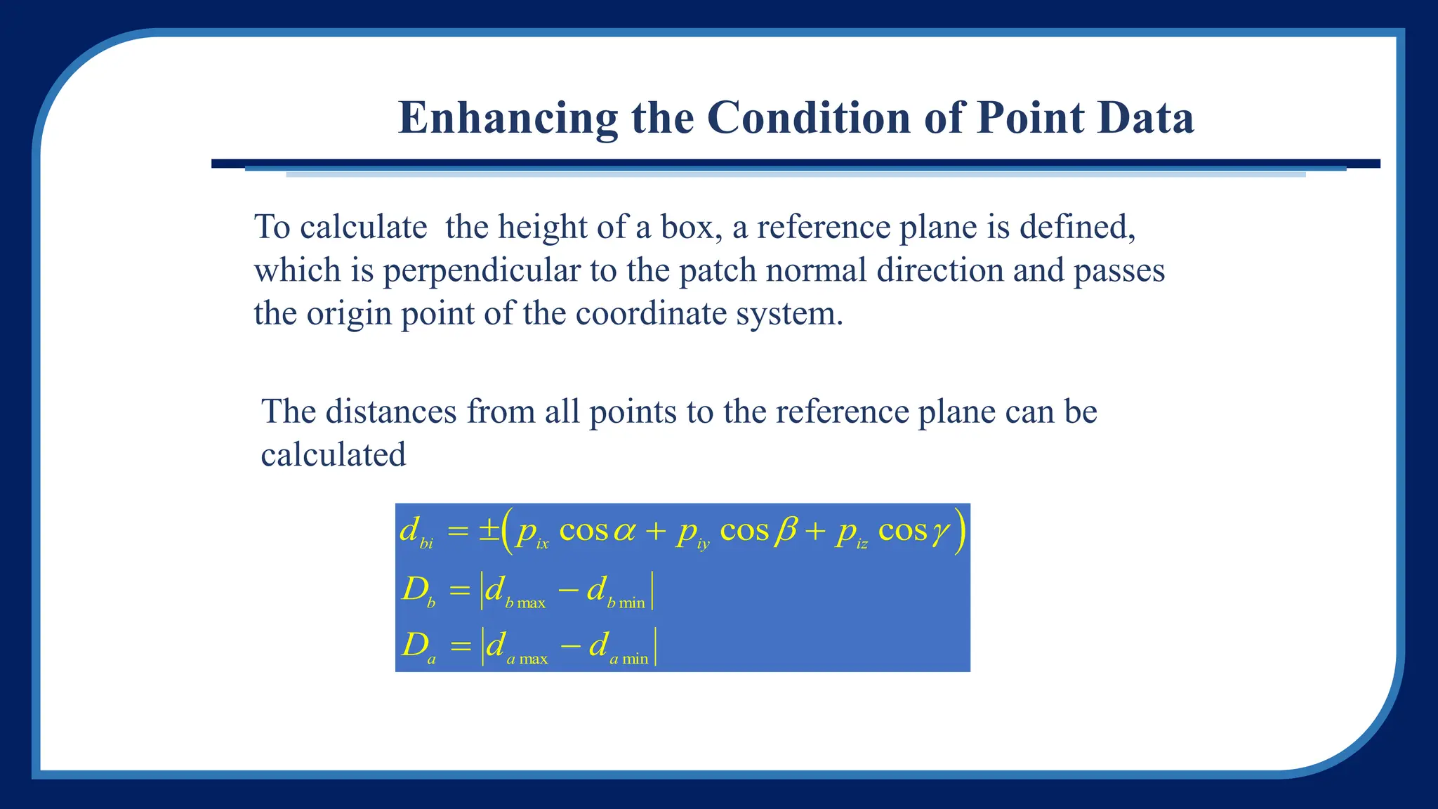
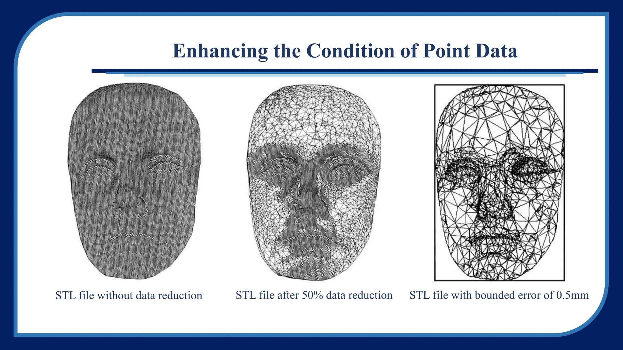
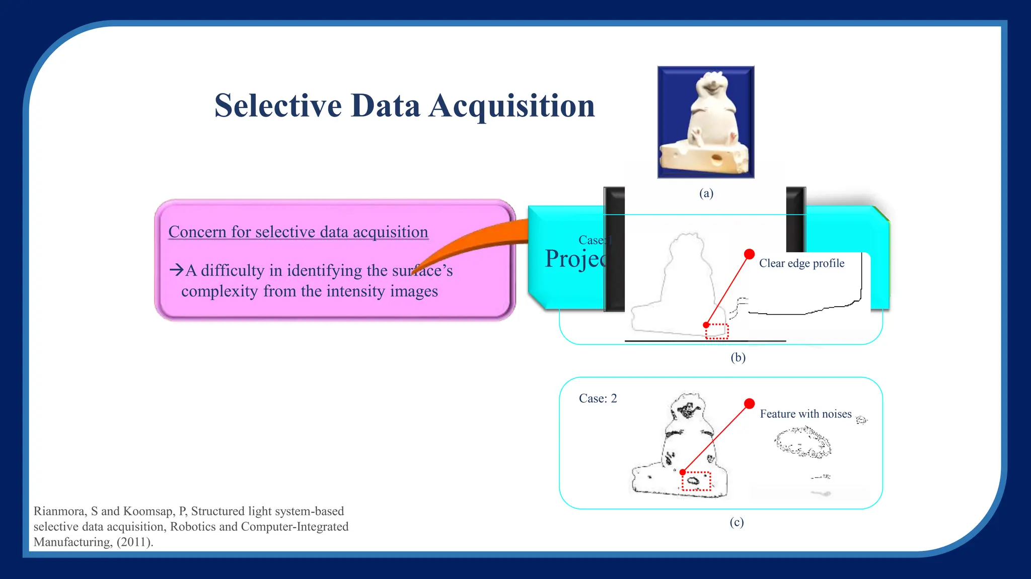
(3) Enhancing point data quality involves estimating normals, registering clouds, and refining models. Segmentation divides data into smooth regions using edge detection, region growing, or hybrid methods. Surface models are then generated from segmented data.