1. Results and Findings
Experiments and Design
The FSS is currently in the engineering testing unit phase, which is posed to help further improve design reliability for the
flight mission. Testing and experiments will include pressure transducers repeatability testing, RTD efficiency and
reliability testing, heat wrap efficiency testing and manifolds heating effectiveness testing. All experimental design was
done by Dr. Mary Coan, Dr. Janine Captain, Lucas Lance, Kate Cryderman, and Beau Peacock.
Pressure Transducer Qualification Testing
• The PT testing comprised of taking the experimental setup and utilizing
pressure changes in conjunction with temperature changes. The PT’s are
used as pressure monitors inside of the manifold, while the rover is
running. Temperature will be kept constant, while the pressure of the
system is changed.
Heat Wrap Analysis Testing
• The goal during the heat wrap analysis test is to determine the most
efficient method to heat trace 1/8th inch stainless steel tubing that
minimizes heat loss and uneven heat distribution. Thermal profile will
help to determine the cooler spots along the tube, where the RTD’s will
be placed.
Mini-Manifold Thermal Profile Testing
• The goal of the Mini-Manifold Test is to determine if the 6’’ piece of
tubing is able to reach a certain temperature with either the line and/or
manifold heaters turned on. The experiment also shows any temperature
inconsistencies across the tube.
RESOLVE (Regolith & Environmental Science & Oxygen & Lunar Volatile Extraction) Project
Abstract
The RESOLVE Project is a lunar prospecting mission whose
primary goal is to characterize water and other volatiles in
lunar regolith. The Lunar Advanced Volatiles Analysis (LAVA)
subsystem is comprised of a fluid subsystem that transports
flow to the gas chromatograph – mass spectrometer (GC-MS)
instruments that characterize volatiles and the Water Droplet
Demonstration (WDD) that will capture and display water
condensation in the gas stream. The LAVA Engineering Test
Unit (ETU) is undergoing risk reduction testing this summer
and fall within a vacuum chamber to understand and
characterize component and integrated system performance.
Testing of line heaters, printed circuit heaters, pressure
transducers, temperature sensors, regulators, and valves in
atmospheric and vacuum environments was done. Test
procedures were developed to guide experimental tests and
test reports to analyze and draw conclusions from the data. In
addition, knowledge and experience was gained with
preparing a vacuum chamber with fluid and electrical
connections. Further testing will include integrated testing of
the fluid subsystem with the gas supply system, near-infrared
spectrometer for the Surge Tank (NIRST), WDD, Sample
Delivery System, and GC-MS in the vacuum chamber.
Ray Parker1,2 parker5@rpi.edu, Dr. Mary Coan1, Dr. Janine Captain1, Kate Cryderman1, Dr. Jacqueline Quinn1
(1) National Aeronautics and Space Administration, John F. Kennedy Space Center, Florida 32899
(2) Department of Chemical and Biological Engineering, Rensselaer Polytechnic Institute, Troy, New York 12180
References
• Coan, Mary. United States. National Aeronautics and Space
Administration. Redundant Heaters For LAVA Trade Study. KSC:
Kennedy Space Center, 2013. Web.
• "In-Situ Resource Utilization Mission." www.nasa.gov. National
Aeronautics and Space Administration. Web. 20 Jul 2013.
<www.nasa.gov/pdf/667862main_FS-2012-07-026-JSC-ISRU-
Fact-Sheet-Screen.pdf>.
• Captain, Janine. "Lunar Advanced Volatile Analysis Vacuum
Demonstration Unit." LAVA 90% Review. National Aeronautics
and Space Administration. Kennedy Space Center, Merritt
Island. 28 Jun 2013. Lecture
Results and Findings (Cont.)
Pressure Transducer Qualification Testing Results
• Each of the PT’s will be installed onto the Integrated Manifold as
part of the Fluid Subsystem. The ETU integrated manifold will help
control the manifold, heaters, temperature and pressure sensors,
orifices, values, tubing and fluid components. The PT test will
allow for a wide range of temperatures and pressures that will
emulate the operational and non-operational modes throughout
the mission lifetime.
Heat Wrap Analysis Results
• Testing of the heat wrap variables has shown that three wraps
per inch results in the least amount of heat loss, reached desired
temperature fastest, most even heat distribution and is easiest to
assemble. More coverage also limits the amount of tubing
exposed, minimizing the risk of potential damage.
Mini-Manifold Thermal Profile Testing Results
• With all heaters (line and both manifold 2 & 4 heaters) at the
same temperature, RTD 1 cannot reach the same temperature,
but remains slightly lower, at steady state. In order to reach
150°C, RTD 1 must be either heated by the power going through
the heaters, insulated, or the metal must be changed in order for
heat to transfer more efficiently.
• RTD 1 is located right near Manifold 2, but because stainless steel
has such a low thermal coefficient compared to Aluminum 6061,
the heat does not transfer over quick enough to heat RTD 1 to
operating temperature. The line heater does disperse energy
evenly, but the aluminum manifold draws heat away from the
stainless steel tubing.
• The lowest temperature areas are located at the ends of the
tube, due to stainless steel thermal coefficient and the stainless
steel bolts. Better line heater is advised and stainless steel tubing
is advised to be replaced with copper or another more
conductive metal.
Conclusion
RESOLVE may lead an essential exploratory expedition in
the future and humankind missions of extraterrestrial
bodies that utilizes resources from surrounding planetary
bodies. RESOLVE may be one of the possible solution to
assist in humankind’s exploration.
Acknowledgements
American Association for the Advancement of Science,
National Aeronautics and Space Administration, KSC Education
Office, Rensselaer Polytechnic Institute
Figure 2. RESOLVE Payload and
Resource Prospector Rover Field
Test Unit. The LAVA subsystem is
depicted in the black box on the
rover. Photo credit: NASA/Dmitri
Gerondidakis
Figure 6. One Wraps/Inch Thermal Profile. Picture
taken after 30 seconds after reaching 150 °C.
RESOLVE is a lunar prospecting
expedition whose primary goal
is to characterize water and
other gas volatiles in lunar
regolith. RESOLVE consists of
LAVA, OVEN, Avionics, Software,
Thermal and Structures
Subsystems. The rover will look
for essential gases inside of
craters, where the remains of
comets (made of ashes, dust
and iced water) will be located.
The rover will then drill into the
lunar soil to extract soil, which
will then be heated inside the
OVEN subsystem.
The Resource Prospector will
complete its mission in seven
days. RESOLVE is a combined
effort between the NASA’s
John F. Kennedy Space Center,
Jet Propulsion Laboratory,
Ames Research Center,
Johnson Space Center,
Marshall Space Flight Center,
and Glenn Research Center
with potential international.
RESOLVE started out as an
exploratory project that took
the proven concept using a
hydrogen reduction reaction
and adding hydrogen to react
with oxides in soil and form
water.
Figure 1. RESOLVE
Logo. RESOLVE
mission patch.
Figure 5. Two Wraps/Inch Thermal Profile. Picture
taken after 30 seconds after reaching 150 °C.
Figure 4. Three Wraps/Inch Thermal Profile. Picture
taken after 30 seconds after reaching 150 °C.
0
20
40
60
80
100
120
363.3
696
1029.2
1363.2
1697.2
2031.1
2365.1
Pressure(atm)
Time (ms)
Pressure
Standard
0
0.005
0.01
0.015
0.02
0.025
0.03
363.3
752.1
1142
1532.3
1922.7
2313
Temperature(C°)
Time (ms)
PT Voltage
23.6
23.7
23.8
23.9
24
24.1
24.2
24.3
24.4
24.5
24.6
363.3
752.1
1142
1532.3
1922.7
2313
Temperature(C°)
Time (ms)
TC Manifold
4.09
4.0905
4.091
4.0915
4.092
4.0925
4.093
363.3
752.1
1142
1532.3
1922.7
2313
Temperature(C°)
Time (ms)
PT Voltage
Supply
Figure 9. Pressure Transducer Testing Outputs. Testing outputs includes pressure
voltage applied, temperature, and voltage supply, from left to right, respectively.
RTD’s
Manifold 4Manifold 2
PTPT
Figure 8. Pressure Transducer Testing Output Diagram. Possible thermal profile of
the mini-manifold system from temperature observations at 10 minutes.
Figure 3. Engineering Test Unit Subsystem Layout.
Fluid Subsystem diagram showing all components of
the RESOLVE payload.
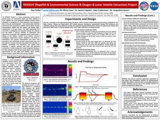
Figure 7. RTD Temperature Testing Results. Possible thermal profile of the mini-
manifold system from temperature observations.
RTD 3RTD 1
Background Information
It was then expanded to
prove that this concept would be able to be done on another
terrestrial body, in order to make essential resources on the moon
or Mars. RESOLVE is a Class D mission and expected to fly in 2020.