SlideShare a Scribd company logo
1 of 28
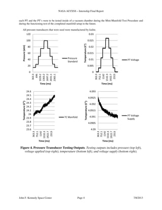
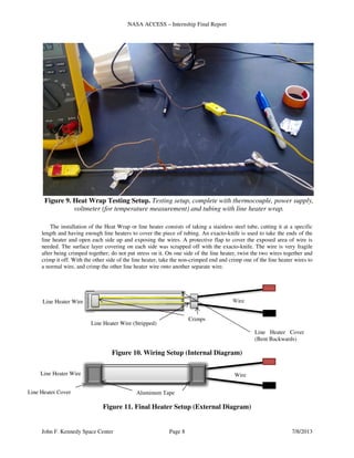
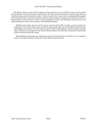
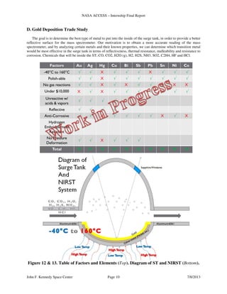
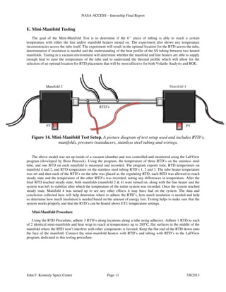
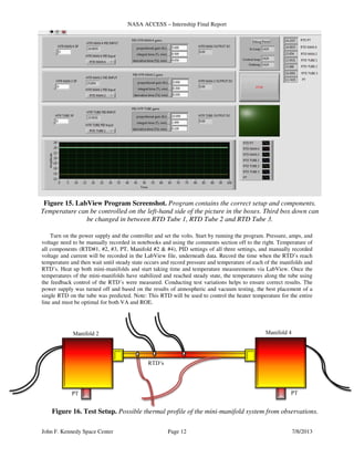
Download to read offline
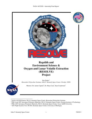
NASA ACCESS – Internship Final Report
John F. Kennedy Space Center i 7/8/2013
Regolith and
Environment Science &
Oxygen and Lunar Volatile Extraction
(RESOLVE)
Project
Ray Parker1
Rensselaer Polytechnic Institute, John F. Kennedy Space Center, Florida, 32899
Mentors: Dr. Janine Captain2
, Dr. Mary Coan3
, Kate Cryderman4
1
NASA ACCESS Intern, NE-L5, Kennedy Space Center, Rensselaer Polytechnic Institute.
2
PhD, Lead AST Aerospace Polymeric Materials, NE-L5, Kennedy Space Center, Georgia Institute of Technology.
3
PhD, AST Aerospace Polymeric Materials, NE-L5, Kennedy Space Center, Texas A&M University.
4
AST Flight Systems Test, NE-M3, Kennedy Space Center, University of Michigan.
NASA ACCESS – Internship Final Report
John F. Kennedy Space Center ii 7/8/2013
Table of Contents
RESOLVE Cover Page i
Table of Contents iii
Nomenclatures, Abbreviations, Acronyms, and Symbols iv
Abstract 1
I. Introduction 1
II. Procedures and Testing 3
A. PT Testing Procedure 3
B. RTD Procedure 5
C. Heat Wrap Analysis Testing 7
D. Gold Deposition Trade Study 10
E. Mini-Manifold Testing 11
III. Analysis and Results 13
A. PT Testing Results 13
B. RTD Procedure Results 13
C. Heat Wrap Analysis Results 13
D. Gold Deposition Trade Study Results 15
E. Mini-Manifold Test Results 16
IV. Conclusion and Recommendations 18
V. Acknowledgments 18
VI. References 18
NASA ACCESS – Internship Final Report
John F. Kennedy Space Center iii 7/8/2013
Nomenclatures, Abbreviations, Acronyms, and Symbols
Term Definition
⁰C Degrees Celsius
ACCESS Achieving Competency in Careers in Engineering and Space Sciences
ACL Applied Chemistry Laboratory
APL Applied Physics Laboratory
ATM Atmosphere
cc Cubic Centimeters
ci Cubic Inches
ESD Electrostatic Discharge
ETU Engineering Test Unit
FSS Fluid Subsystem
FTU Field Test Unit
g Grams
GC Gas Chromatograph
GSE Ground Support Equipment
GSS Gas Supply System
IPA Isopropyl Alcohol
JPL Jet Propulsion Laboratory
K Kelvin
kg Kilograms
KSC Kennedy Space Center
LAVA Lunar Advanced Volatile Analysis
MCOTS Modified Commercial off the Shelf
MS Mass Spectrometer
NE-L5 Applied Physics Laboratory Mail Code
NIRST Near Infrared Spectrometer for Surge Tank
OVEN Oxygen Volatile Extraction Node
PID Proportional-Integral-Derivative
PPE Personal Protective Equipment
psia Pounds per Square Inch at Atmospheric Pressure
PT Pressure Transducer
QA Quality Assurance
RESOLVE Regolith and Environment Science and Oxygen and Lunar Volatile Extraction
ROE Regolith Oxygen Extraction
RTD Resistive Temperature Detector
SBU Sensitive But Unclassified
SDS Sample Delivery System
SS Stainless Steel
ST LAVA Surge Tank
TEC Thermal Electric Cooler
TS Temperature Sensors
UHP Ultra High Purity (99.999%)
VA Volatile Analysis
WDD Water Droplet Demonstration
Chemical Formula (Mass) Name Chemical Formula (Mass) Name
H2O (18 g/mol) Water H2S (34.08 g/mol) Hydrogen sulfide
CO (28.05 g/mol) Carbon monoxide NH3 (28.01 g/mol) Ammonia
O2 (32 g/mol) Oxygen SO2 (64.07 g/mol) Sulfur dioxide
C2H4 (28 g/mol) Ethylene OH (17 g/mol) Hydroxide
CO2 (44.01 g/mol) Carbon dioxide HF (20.01 g/mol) Hydrogen fluoride
H2 (2 g/mol) Hydrogen HCl (36.46 g/mol) Hydrochloric acid
NASA ACCESS – Internship Final Report
John F. Kennedy Space Center Page 1 7/8/2013
Abstract. The RESOLVE project is a lunar prospecting mission whose primary goal is to
characterize water and other volatiles in lunar regolith. The Lunar Advanced Volatiles Analysis
(LAVA) subsystem is comprised of a fluid subsystem that transports flow to the gas chromatograph –
mass spectrometer (GC-MS) instruments that characterize volatiles and the Water Droplet
Demonstration (WDD) that will capture and display water condensation in the gas stream. The LAVA
Engineering Test Unit (ETU) is undergoing risk reduction testing this summer and fall within a
vacuum chamber to understand and characterize component and integrated system performance.
Testing of line heaters, printed circuit heaters, pressure transducers, temperature sensors, regulators,
and valves in atmospheric and vacuum environments was done. Test procedures were developed to
guide experimental tests and test reports to analyze and draw conclusions from the data. In addition,
knowledge and experience was gained with preparing a vacuum chamber with fluid and electrical
connections. Further testing will include integrated testing of the fluid subsystem with the gas supply
system, near-infrared spectrometer, WDD, Sample Delivery System, and GC-MS in the vacuum
chamber. This testing will provide hands-on exposure to a flight forward spaceflight subsystem, the
processes associated with testing equipment in a vacuum chamber, and experience working in a
laboratory setting. Examples of specific analysis conducted include: pneumatic analysis to calculate
the WDD’s efficiency at extracting water vapor from the gas stream to form condensation; thermal
analysis of the conduction and radiation along a line connecting two thermal masses; and
proportional-integral-derivative (PID) heater control analysis. Since LAVA is a scientific subsystem,
the near-infrared spectrometer and GC-MS instruments will be tested during the ETU testing phase.
I. Introduction
NASA (National Aeronautics and Space Administration) exploration of extraterrestrial bodies is increasingly
growing as well as what materials that can be gained from these lunar bodies. In future human exploration of space,
NASA has an increasing interest in obtaining resources from outside of our own planetary system and using these
resources as essential resources to help humans survive in the unforgiving climates of space, and lunar bodies such
as Mars.
The RESOLVE (Regolith and Environment Science and Oxygen and Lunar Volatile Extraction) project is a
lunar prospecting mission whose primary goal is to characterize water and other gas volatiles in lunar regolith.
RESOLVE consists of LAVA (Lunar Advanced Volatile Analysis), OVEN (Oxygen Volatile Extraction Node),
Avionics, Software, Thermal and Structures Subsystems. The Lunar Advanced Volatiles Analysis (LAVA)
subsystem, interfaces with all of the other RESOLVE subsystems, is comprised of a fluid subsystem that transports
flow to the gas chromatograph – mass spectrometer (GC-MS) instruments that characterize volatiles and the Water
Droplet Demonstration (WDD) that will capture and display water condensation in the gas stream. In addition to
being comprised of the GC (Gas Chromatograph) and MS (Mass Spectrometer), LAVA is also made up by the SDS
(Sample Delivery System), FSS (Fluid Subsystem) and GSE (Ground Support Equipment). The Fluid Subsystem is
primarily what will be focused on during the duration of this report, and includes the NIRST (Near Infrared
Spectrometer for Surge Tank), WDD (Water Droplet Demonstration), Integrated Manifold and GSS (Gas Supply
System). The Integrated Manifold consists of the Manifold, Heaters, Pressure Transducers (PT), Temperature
Sensors (TS), and Orifices/Tubing.
The RESOLVE rover will be sent to prove that water can be accessible on the moon and other planetary bodies,
and that there is enough regolith, or lunar soil, to make air for astronauts, fuel for rockets, or water for plants. The
rover will look for essential gases inside of craters, where the remains of comets (made of ashes, dust and iced
water) will be located. The rover will then use its drill, which is designated to burrow a yard into the lunar soil to
extract soil, of which will be put into the OVEN. OVEN will then heat the soil, which will release the gas particles
into a streamline to lead to the ST/NIRST, which will then vent the fast flowing gas molecules to the SDS/GC-MS,
or WDD subsystems.
While inside of the ST, the GC-MS analyzes the mass of the particles using the near infrared spectrometer to
determine the identity of the particles. The GC-MS will allow for scientific data to be transmitted back to Earth to
provide more information on particles of matter on other planetary bodies. The gas inside of the ST can also go to
the WDD or Water Droplet Demo, ran through ROE, or can be vented out of the system. Within the WDD, the
NASA ACCESS – Internship Final Report
John F. Kennedy Space Center Page 2 7/8/2013
particles of gas (CO, CO2, H2O, H2, H2S, NH3, SO2, C2H4, HF and HCl) are moved into the system along with
hydrogen gas that ejects into the WDD as well, causing the OH molecules to condense inside of the WDD causing
water droplets to form in the state of condensation. A picture will be taken of the processes and will be sent back to
Earth, showing that water can be made on the moon or another planetary body with the right conditions.
Figure 1. RESOLVE Subsystem ETU Layout. LAVA Subsystem is depicted inside box, with
the WDD and fluid valves/lines on the right, and the OVEN/GC-MS/SDS subsystems on the left.
Regolith Oxygen Extraction (ROE) is a process that
involves LAVA and OVEN, and is the same procedure
as before, but instead at a much higher temperature.
OVEN heats the regolith to 900°C, instead of 150°C,
and Hydrogen is supplied and reacts with the oxygen in
the regolith to form water which flows into the ST.
Fluoride and other unwanted species can also react with
the hydrogen at high temperatures and form acidic
species. Along with the more gaseous molecules,
fluoride ions and other unwanted molecules may be
present and bond with the existing molecules to cause
complications, of which could damage or lower the
accuracy of the instruments. Because of this, ROE will
not be used until RESOLVE has completed all other
essential tasks, such as the WDD or GC-MS analysis.
Figure 2. RESOLVE Moon Rover Field
Test Unit. The LAVA subsystem is depicted
in the black box on the rover. Photo credit:
NASA/Dmitri Gerondidakis
NASA ACCESS – Internship Final Report
John F. Kennedy Space Center Page 3 7/8/2013
The rover is to complete its mission in 10 days on the
moon and projected to last no more than a month on the
moon, due to large temperature drops on the inside of the
craters on the moon. RESOLVE is a combined effort
between the National Aeronautics and Space Administration
(NASA), NASA’s John F. Kennedy Space Center, NASA’s
Jet Propulsion Laboratory (JPL), NASA’s Ames Research
Center (ARC) and the Canadian Space Agency (CSA). The
RESOLVE project started out as an exploratory project that
took the proven concept using a hydrogen reduction reaction
and adding Hydrogen to react with oxides in soil and form
water. It was then expanded to prove that this concept would
be able to be done on another terrestrial body, other than the
Earth, in order to make essential resources, such as water,
on the moon or Mars. NASA is working towards using the
few resources on other terrestrial bodies and turning them
into resources that will help discover the rest of the solar
system. RESOLVE is a Class D mission and the mission
payload is expected to fly in 2018.
The duration of the internship focuses mainly on the LAVA and FSS subsystem. Procedure writing, testing and
analysis were all done on certain aspects of the ETU build. The following will address developed procedures and
experiments, along with the results of the experiments and their effect on the RESOLVE ETU rover.
II. Procedures and Testing
The FSS is currently in the ETU testing phase, in which certain factors from the FTU are being modified to be
better suited for flight mission. Testing was all done for the FSS, in which certain factors and concepts were tested
and figured to be favored over the other. This internship focuses on testing, analyzing and evaluating certain points
on the FSS FTU and modifying them for maximum efficiency. Pressure Transducers were tested for repeatability.
RTD Experimental Procedures were modified and improved for further efficiency. Heat wrapping was analyzed for
maximum heating and efficiency. Abstract modification concepts were researched and analyzed for the Gold
Deposition Trade stud and experimentation thinking and pneumatic analysis were done on the Mini-Manifold
Analysis Testing. All procedures that were done in this section were done in O&C Laboratory 1292, under
supervision of Mary Coan, Janine Captain, Lucas Lance, Kate Cryderman and/or Beau Peacock. All procedures will
be addressed in Section II, follow by results in Section III and conclusion in Section IV.
A. PT Testing Procedure
Pressure Transducer testing was done to help ensure repeatability of the PT’s inside of the vacuum chamber and
at atmospheric pressure. The PT testing was done using a LabView Program and an experimental manifold setup
with National Instrument NI adaptor sensors, of which were set up by Beau Peacock.
The PT testing comprised of taking the experimental setup and utilizing pressure changes in conjunction with
temperature changes. The PT’s are used as pressure regulators inside of the manifold, while the rover is running.
Temperature was kept constant, while the pressure of the system was changed in certain increments, each of which
lasted about seven or so minutes. Pressure started at ATM, went to 25 pisa (pounds per square inch absolute), 50
pisa, 75 pisa, 100 pisa, and then back down to 75 pisa, 50 psia, 25 pisa, and then back to ATM. Each test took about
30 minutes to complete, and each temperature level, (25°C, 50°C, 75°C, 100°C, 150°C and 175°C) needed to be
tested three times each for repeatability and quality assurance.
There will be three PT’s that will be used inside of the Integrated Manifold for ETU, which will help transfer
fluids and gases along their expected paths. RTD’s (Resistance Thermal Detectors) are placed onto the surface of
Figure 3. RESOLVE Rover Field Test
Unit. RESOLVE rover being tested on the
Hawaiian Islands (Big Island). Photo credit:
NASA/Joe Bibby
NASA ACCESS – Internship Final Report
John F. Kennedy Space Center Page 4 7/8/2013
each PT and the PT’s were to be tested inside of a vacuum chamber during the Mini-Manifold Test Procedure and
during the functioning test of the completed manifold setup in the future.
All pressure transducers that were used were manufactured by kulite.
Figure 4. Pressure Transducer Testing Outputs. Testing outputs includes pressure (top left),
voltage applied (top right), temperature (bottom left), and voltage supply (bottom right).
0
20
40
60
80
100
120 363.3
696
1029.2
1363.2
1697.2
2031.1
2365.1
Pressure(atm)
Time (ms)
Pressure
Standard
0
0.005
0.01
0.015
0.02
0.025
0.03
363.3
752.1
1142
1532.3
1922.7
2313
Temperature(C°)
Time (ms)
PT Voltage
23.6
23.7
23.8
23.9
24
24.1
24.2
24.3
24.4
24.5
24.6
363.3
752.1
1142
1532.3
1922.7
2313
Temperature(C°)
Time (ms)
TC Manifold
4.09
4.0905
4.091
4.0915
4.092
4.0925
4.093
363.3
752.1
1142
1532.3
1922.7
2313
Temperature(C°)
Time (ms)
PT Voltage
Supply
NASA ACCESS – Internship Final Report
John F. Kennedy Space Center Page 5 7/8/2013
B. RTD Procedure
The LAVA Resistance Temperature Detector (RTD) Test will allow for a wide range of temperatures that will
emulate the operational and non-operational modes throughout the mission lifetime. Testing the RTD at 14.7 psia, or
Earth’s Atmosphere, affords the designer the ability to discriminate phenomenon and error associated with the
vacuum of space.
Testing the RTD in a vacuum equal to or below 1x10⁻⁵
torr affords the designer the ability to discriminate
phenomenon and error associated with Earth’s Atmosphere and allows the RTD to function in an environment
similar to the Moon. An oven will be used to heat and cool an isothermal block that the RTDs will be mounted to in
earth’s atmosphere. A temperature standard will be used in the oven to verify the accuracy of the RTD unit under
test in earth’s atmosphere and in vacuum. The RTD’s will be attached to certain parts of the manifold and rover to
help determine temperature and be used as a feedback control regulator.
Figure 5. RTD Model. A picture showing the proper side to mount to the metal surface in this
experiment.
Figure 6. LAVA Resistance Temperature Detector Experimental Test Set-up in Vacuum.
(Provided by Mary Coan)
The adhesion of an RTD to a metal consists of taking a silicon adhesive and applying the RTV onto a metallic
surface and placing in a RTD onto it in order to create a sustaining vacuum-rated sealant, temperature sensor and
bond network. The adhesive is made using a liquid part and solid part of which should be weigh and mixed
according to the data sheet provided for the specific adhesive. Keep in mind that the adhesive has a short working
NASA ACCESS – Internship Final Report
John F. Kennedy Space Center Page 6 7/8/2013
life time, so be sure to consult a data sheet prior to mixing to ensure enough time will be available. Utilize pre-wired
RTD’s, this way soldering does not damage or destroy manifold or component with the RTD on it.
Figure 7. Experimental Procedure. Enough adhesive is place to cover the bottom part of the
RTD and keep it off the manifold.
If not readily available, it is advisable to solder wires to the RTD leads prior to adhering to the metal surface.
The metal surface and RTD are cleaned with alcohol; keep in mind that alcohol is flammable and an irritant. The
RTD must not be too far away from the manifold, or else the temperature measurement may be off by a couple
degrees.
Then place tape down to protect the other sides of the manifold in order to keep other parts from being in contact
with the adhesive. If the tape is used, it is necessary to use a sharp knife blade to carefully cut the adhesive from the
tape, rather than peeling the tape from under the adhesive. RTV Silicone Rubber Adhesive Mixtures are sensitizers.
Resin Part A is an irritant and sensitizer. Catalyst Part B is an irritant. Exposure may cause eye and skin
irritation, sensitization and burns. Wear safety glasses with side shields, nitrile (Sol-Vex) gloves, chemical
protectant sleeves or shop coat. Do not touch the adhesive with Nitrile or Latex Gloves. The gloves will cause the
adhesive to chemically break down. If adhesive must be touched, utilize PVC gloves. Do not place the adhesive or
RTD wires where the potential to block vital functions is possible such as bolts, screws, moving devices, etc. The
RTD leads shall not touch the metal surface or each other. Cover the leads with tape before curing and solder joints
with vacuum rated heat shrink, if prewired RTDs are used. If the leads touch each other or the manifold surface, a
short may occur and could be grounded out.
NASA ACCESS – Internship Final Report
John F. Kennedy Space Center Page 7 7/8/2013
Figure 8. Complete Product. Completed RTD attachment to a flat metal surface (no wires).
The RTD is placed on the adhesive using tweezers. The RTD is pressed into the adhesive using the adhesive-
applying tool, and then a piece of tape is placed over the RTD wires while pressing the RTD down. Cover the entire
RTD and exposed leads with additional adhesive. The adhesive shall be cured according to the manufacturer data
sheets. Using thermal protective gloves, remove the mounted surface and the attached RTDs from the oven ensuring
due care while handling the assembly. Heat generating equipment produces high surface temperatures. Contact with
hot equipment or heated materials may cause severe burns. Usage near combustible materials, vapors or ordnance
may result in fire and/or explosion causing severe injury or death. Flat surface of the RTD must be in contact with
the metal surface in order to ensure accuracy in temperature reading. Tape may be advised to be kept on until
soldering is started, due to the possibility of reattaching the RTD and adhesive from the metallic surface.
In order to check if the RTD is working properly, a voltmeter or multi-meter is taken and put onto resistance
measurement setting. The two leads are then touched by the two multi-meter probes and the resistance is taken.
RTD’s should have around one kilo-ohm of resistance. While touching one probe to the wire, take the other probe
and touch the piece of tubing to make sure no ohms are being recorded. Then take the other leads and make sure it
doesn’t have any resistance reading. Testing reduces the chances of the RTD’s grounding out or failing during
testing and ensures quality of the RTD adhering procedure. If the RTD is coming out of the adhesives or is not laid
flat against the manifold or tubing, the entire procedure must be redone. Adhering RTD’s can be difficult but can be
made easier by having two appliers.
C. Heat Wrap Analysis Testing
The goal during the heat wrap analysis test is to determine the most efficient method to heat trace 1/8th inch
stainless steel tubing that minimizes heat loss and uneven heat distribution. Thermal profile will help to determine
the cooler spots along the tube, where the RTD’s will be placed. This will also help us determine the most effective
method of wrapping the line heater onto the tube. The data and conclusion collected here will help determine which
type of wrapping style will be used on the ETU. The testing of the line heater wrap for initial testing has concluded
that for wrapping line heater around a 6 inch tube that; 3 Wraps/in – 27 inches of heater per 1 foot tube, 2 Wraps/in
– 16 inches of heater per 1 foot tube, 1 Wraps/in – 13.5 inches of heater per 1 foot tube. Thermal images/heat
profiles of each of the tubes were taken to see which wrapping method would be most effective and what will be
used for the remainder of the ETU design.
NASA ACCESS – Internship Final Report
John F. Kennedy Space Center Page 8 7/8/2013
The installation of the Heat Wrap or line heater consists of taking a stainless steel tube, cutting it at a specific
length and having enough line heaters to cover the piece of tubing. An exacto-knife is used to take the ends of the
line heater and open each side up and exposing the wires. A protective flap to cover the exposed area of wire is
needed. The surface layer covering on each side was scrapped off with the exacto-knife. The wire is very fragile
after being crimped together; do not put stress on it. On one side of the line heater, twist the two wires together and
crimp it off. With the other side of the line heater, take the non-crimped end and crimp one of the line heater wires to
a normal wire, and crimp the other line heater wire onto another separate wire.
.
Aluminum Tape
Crimps
Line Heater Wire (Stripped)
Wire
WireLine Heater Wire
Line Heater Wire
Figure 9. Heat Wrap Testing Setup. Testing setup, complete with thermocouple, power supply,
voltmeter (for temperature measurement) and tubing with line heater wrap.
Figure 10. Wiring Setup (Internal Diagram)
Line Heater Cover
(Bent Backwards)
Line Heater Cover
Figure 11. Final Heater Setup (External Diagram)
NASA ACCESS – Internship Final Report
John F. Kennedy Space Center Page 9 7/8/2013
The adhesive silicon was put onto the crimped and exposed portion of wire and fold covering over the exposed
part on both sides of the wire to create a sealed system. The silicon was then cured and covered with tape, then was
tested by running current through the system. In order to test the wires, banana clips are attached and the papered
layer of the line heater was torn off and stuck to the tube with the number of wraps per inch needed to be tested. A
thermocouple was put in between in order to test the temperature correctly. The line heater may smoke due to the
adhesive burning off; make sure to use gloves when handling hot objects.
Multiple thermocouples may be used to increase accuracy and the PID controller is used to regulate the
temperature of the system. Positive wire into the line heater and the other wire into the PID controller, then the
thermocouple are attached to the PID and the system should be self-regulating. Thermal images were then
taken. This processes and analysis of the tube line heaters enables the LAVA team to determine which thermal
profile would best suit the ETU design.
When handling the line heater, the crimped areas at the end of the line heater, where the wires are connected,
may be very fragile and likely to break once moved, shifted or adjusted about.
NASA ACCESS – Internship Final Report
John F. Kennedy Space Center Page 10 7/8/2013
D. Gold Deposition Trade Study
The goal is to determine the best type of metal to put into the inside of the surge tank, in order to provide a better
reflective surface for the mass spectrometer. Our motivation is to obtain a more accurate reading of the mass
spectrometer, and by analyzing certain metals and their known properties, we can determine which transition metal
would be most effective in the surge tank in terms of reflectiveness, thermal resistance, malleability and resistance to
corrosion. Chemicals that will be inside the ST; CO, CO2, H2O (g), H2, H2S, NH3, SO2, C2H4, HF and HCl.
Figure 12 & 13. Table of Factors and Elements (Top). Diagram of ST and NIRST (Bottom).
NASA ACCESS – Internship Final Report
John F. Kennedy Space Center Page 11 7/8/2013
E. Mini-Manifold Testing
The goal of the Mini-Manifold Test is to determine if the 6’’ piece of tubing is able to reach a certain
temperature with either the line and/or manifold heaters turned on. The experiment also shows any temperature
inconsistencies across the tube itself. The experiment will result in the optimal location for the RTD across the tube,
determination if insulation is needed and the understanding of the heat profile of the SS tubing between two heated
manifolds. Testing in a vacuum environment will determine whether the manifold and line heaters are able to supply
enough heat to raise the temperature of the tube and to understand the thermal profile which will allow for the
selection of an optimal location for RTD placement that will be most effective for both Volatile Analysis and ROE.
The above model was set up inside of a vacuum chamber and was controlled and monitored using the LabView
program (developed by Beau Peacock). Using the program, the temperature of three RTD’s on the stainless steel
tube, and one RTD on each manifold is measured and recorded. The program exports time, RTD temperature on
manifold 4 and 2, and RTD temperature on the stainless steel tubing RTD’s 1, 2 and 3. The tube heater temperature
was set and then each of the RTD’s on the tube was placed as the regulating RTD, each RTD was allowed to reach
steady state and the temperature of the other RTD’s was recorded, noting any differences in temperature. After the
final RTD reached steady state, both manifolds (manifold 2 & 4) were turned on, along with the line heater and the
system was left to stabilize after which the temperature of the entire system was recorded. Once the system reached
steady state, Manifold 4 was turned up to see any other effects it may have had on the system. The data and
conclusion collected here will help determine where to adhere the RTD’s, how much insulation is needed and help
us determine how much insulation is needed based on the amount of energy lost. Testing helps to make sure that the
system works properly and that the RTD’s can be heated above ETU temperature settings.
Mini-Manifold Procedure
Using the RTD Procedure, adhere 3 RTD’s along locations along a tube using adhesive. Adhere 1 RTD to each
of 2 identical mini-manifolds and heat wrap to reach at temperatures up to 200°C, flat surfaces in the middle of the
manifold where the RTD won’t interfere with other components is favored. Keep the flat end of the RTD down onto
the face of the manifold. Connect the mini-manifold heaters with RTD’s and tubing with RTD’s to the LabView
program, dedicated to this testing procedure.
PT
Manifold 4
PT
RTD’s
Manifold 2
Figure 14. Mini-Manifold Test Setup. A picture diagram of test setup used and includes RTD’s,
manifolds, pressure transducers, stainless steel tubing and wirings.
NASA ACCESS – Internship Final Report
John F. Kennedy Space Center Page 12 7/8/2013
Turn on the power supply and the controller and set the volts. Start by running the program. Pressure, amps, and
voltage need to be manually recorded in notebooks and using the comments section off to the right. Temperature of
all components (RTD#1, #2, #3, PT, Manifold #2 & #4), PID settings of all three settings, and manually recorded
voltage and current will be recorded in the LabView file, underneath data. Record the time when the RTD’s reach
temperature and then wait until steady state occurs and record pressure and temperature of each of the manifolds and
RTD’s. Heat up both mini-manifolds and start taking time and temperature measurements via LabView. Once the
temperatures of the mini-manifolds have stabilized and reached steady state, the temperatures along the tube using
the feedback control of the RTD’s were measured. Conducting test variations helps to ensure correct results. The
power supply was turned off and based on the results of atmospheric and vacuum testing, the best placement of a
single RTD on the tube was predicted. Note: This RTD will be used to control the heater temperature for the entire
line and must be optimal for both VA and ROE.
RTD’s
Manifold 4Manifold 2
PTPT
Figure 16. Test Setup. Possible thermal profile of the mini-manifold system from observations.
Figure 15. LabView Program Screenshot. Program contains the correct setup and components.
Temperature can be controlled on the left-hand side of the picture in the boxes. Third box down can
be changed in between RTD Tube 1, RTD Tube 2 and RTD Tube 3.
NASA ACCESS – Internship Final Report
John F. Kennedy Space Center Page 13 7/8/2013
III. Analysis and Results
In the following section, the importance of the experiments and the impact of the analysis will be considered for
each of the procedures addressed above in Section II. Each of these analyses will directly impact ETU testing of the
RESOLVE rover. Results of the PT Testing, RTD Procedure, Heat Wrap Analysis, Gold Deposition and Mini-
Manifold Testing will be discussed in this section. Due to Export Control reasons, numbers and data will not be
addressed directly. All experimentation was completed at Kennedy Space Center inside of O&C 1292 by Ray
Parker, Janine Captain, Mary Coan, Kate Cryderman, Lucas Lance and Beau Peacock.
A. PT Testing Results
The outcomes of the PT testing will allow for the proper calibrations of the PT’s functioning properly during
ETU testing. Each of the PT’s will be installed onto the Integrated Manifold as part of the FSS. The ETU Integrated
manifold helps control the ETU manifold, heaters, temperature & pressure sensors, and the orifices, values tubing
and fluid components. The PT test will allow for a wide range of temperatures and pressures that will emulate the
operational and non-operational modes throughout the mission lifetime. It tested the pressure transducer at ATM,
and through a variety of different pressures and temperatures. Being able to calibrate these sensitive tools will allow
for the fluids/gases inside of the FSS to move with ease throughout the operational flow of the system while the
system is in operation. See Figure 4.
B. RTD Procedure Results
The RTD Procedure established a baseline procedure on adhering RTD’s onto various temperature sensitive
equipment for the FSS, in a flight forward manner. RTD’s will be attached to the Integrated Manifold, manifold,
manifold and tube heaters, PT’s, and tubing. Due to the thermal conductivity of the RTV, the RTD’s may be
inaccurate to the extent of a few degrees. Possible lessons that can be learned from the RTD Procedure include
making sure that the RTD’s won’t block or inhibit any vital functions of the system that it is being installed on, do
not use any tape for it makes preparing the finished product more difficult, make sure to bend the prewired RTD’s
concave downwards in order to keep them on tighter, and make sure and keep the conducting lead wires off of the
metallic surface to prevent the RTD from grounding out.
C. Heat Wrap Analysis Results
Testing of the different heat wraps has shown that 3 wraps per inch results in the least amount of heat loss,
quickest to reach temperature, best heat distribution along the stainless steel tubing and is the easiest method to wrap
tubing with. A secondary benefit is the limited amount of tubing exposed to the environment minimizing the risk of
potentially damaging the under layer of the heater tape (heat wrap).
The RESOLVE rover functions using heaters as a means of transporting its payload (gases). These heaters are
essential to the rover in order to complete its mission objective and must be able to heat its tubing to at least 150°C.
As a result, more line heater must be added onto the tubing, which thus increases the mass of the system as well as
the amount of power that is needed to power the tubes. The more mass, more power, the less mass less power
conflict comes into play again and for this situation, and the more mass more power was chosen for this situation,
because the system must reach 150°C, and must be able to heat itself as most effectively as it can, and since the
more spread out the wraps are, the more energy is escaping and being exposed to the atmosphere/space, then the
most logical wrap would be the one that insulates itself the beset and heats the tubing to the correct temperature at a
faster rate. This in turn creates a better line heater wrap and an overall system.
NASA ACCESS – Internship Final Report
John F. Kennedy Space Center Page 14 7/8/2013
-Not as much heat loss here as compared to the other wraps.
-Seems tight on the tubing.
-Very diverse range of temperature; even more than 2 wraps/in or 3 wraps/in.
-Has very cool spots along the tube itself.
-More consistent release of heat at each of the spots where the tube is shown.
-Very consistent in terms of temperature range.
-Several areas in between spiral reached +150 °C.
-Much more heat is lost here as compared to the 3 wraps/inch case.
-Wrap is less consistent in terms of spacing and seperation.
Figure 17. 3 Wraps/Inch Thermal Profile. Picture taken after 30 seconds after reaching 150 °C.
Figure 18. 2 Wraps/Inch Thermal Profile. Picture taken after 30 seconds after reaching 150 °C.
NASA ACCESS – Internship Final Report
John F. Kennedy Space Center Page 15 7/8/2013
-Much more divergence in temperature scaling.
-Doesn’t look tightly on the tube.
-Tube is not heated very well and seems relatively cool.
D. Gold Deposition Trade Study Results
Trade studies are studies that are put into place in order to justify
designs or functionalities of certain components. In design reviews,
questions that come up as to why a design was built the way it was,
and thus conflicting answers come up. Trade studies allow for the
designers to show the thought process as to how an idea was agreed
upon. Usually it consists of multiple designs each of which has certain
flaws and one is agreed upon.
LAVA is trying to determine is the potential issues with
depositing gold onto Al 6061. The Al 6061 is concave up and is the
inside of the ST. This means that the layer will see temperature
swings of -40 to 160C and be in contact with water vapor and various
other acids in the gas stream. It is important we understand the
process for depositing of Gold onto Al 6061, what layers are needed
between the Al and Gold, how much Au would need to be deposited,
is polishing the surface to make the surface defect free possible,
would this react with any of the gases that we might see, etc.?
Using the evidence researched in the Gold Deposition Case Study,
the conclusion is to reuse the ETU design for future Flight testing.
The optical cable/emitter, receiver and the pass-through NIR system
are to remain the same, due to the high costs of adding the layered
deposition, overall complexity of the system, and metallic properties
(thermal coefficients, softening temperatures, reflectiveness, and
being Hydrogen Embriddlement- Resistant). The Gold Deposition Trade study has helped to address future inquiries
regarding the design of the MS/ST and the difference between the pass-through NIR System and the Reflective NIR
system.
Figure 19. 1 Wraps/Inch Thermal Profile. Picture taken after 30 seconds after reaching 150 °C.
Figure 20. ST. Surge Tank covered
with a heater.
NASA ACCESS – Internship Final Report
John F. Kennedy Space Center Page 16 7/8/2013
E. Mini-Manifold Test Results
The Mini-Manifold Heater Test Procedure was followed for the beginning of this experiment. The experiment
was completed inside a vacuum chamber. The vacuum chamber’s base/starting pressure rose to a maximum when all
of the heaters were on and the entire system was off-gassing. See Figure 17.
Figure 21. Mini-Manifold Results. Graph showing RTD#1, RTD#2, and RTD#3 temperatures.
The manifold 2 and 4 heaters were turned on while the tube heater was still hot and the RTD#3 was heated. After
half an hour, the average temperature was about the same for all the RTD’s. RTD #3 was chosen as the “HTR TUBE
PID Input”, because it theoretically is the coolest stop on the tube, thus being the most probable location of the RTD
during ETU.
Differential temperature was tested next. Manifold 4 was heated, while the rest of the heaters remained the same.
After reaching steady state in 10 minutes, Manifold 4 was higher than Manifold 2, RTD#3 and RTD#2 were the
same and RTD#1 was lower. No temperature change for any of the RTD’s occurred, due to the poor thermal
coefficient of stainless steel tubing, thus more time and wattage would be invested, leading to instead focus more
wattage at the tube heater for a shorter amount of time rather than waiting for convection to spread the heat across
the mini-manifolds and stainless steel tubing.
With all heaters (line and both manifold 2 & 4 heaters) at the same temperature, RTD #1 cannot reach the same
temperature, but remains slightly lower, at steady state. If RTD#1 must be exceeded this temperature options
include, increase the amount of power going through the heaters, insulation must be added, or the metal must be
changed in order for the heat to transfer from over from the manifold #2 and #4 into the tube. RTD#1 is located right
near manifold #2, but because stainless steel has such a low thermal coefficient compared to Al 6061, the heat does
not transfer over quick enough to heat RTD#1 up. The line heater does heat evenly, but the aluminum manifold
draws heat away from the stainless steel tubing. This explains why RTD#1, which is very close to the manifold, is so
low in temperature and why RTD#3 is so much higher in temperature.
The RTD#1’s temperature is drastically different from RTD#3’s, (over 50°C in some instances), due to the
thermal coefficients and thermal profile of the metals. Other factors may play a role in this as well, such as thickness
of the adhesive holding the RTD on, uneven contact of the RTD’s against the stainless steel, or the location of the
RTD’s. The RTD’s may be situation on top of a cold spot in between the heat wrapped layers (avoiding the thermal
conducting wires). RTD#1 does have mechanical defects and cannot be completely reliable.
0
50
100
150
200
250
0.001
1.535
3.07
4.605
6.139
7.674
9.209
10.743
12.278
13.813
15.347
16.882
18.417
19.951
21.486
23.021
24.555
26.09
27.625
29.159
30.694
32.229
Degrees(°C)
Time (Minutes)
RTD#1
RTD#2
RTD#3
Temperature Average
NASA ACCESS – Internship Final Report
John F. Kennedy Space Center Page 17 7/8/2013
Due to the radiation of heat off all three heaters, adding some sort of insulation will help to increase the
temperature of the system. Due to the stainless steel, neither of the two manifolds (#2/#4) heaters have much of an
effect on them, thus increasing the manifold heaters won’t change the RTD’s temperatures until time has passed.
The line heater on the RTD’s will be able to supply enough heat to heat the RTD’s up. Due to gas flow and heat
transfer coming from OVEN and the LOVEN Line, it may be able to heat up but in order to ensure the target
temperature is reached, all heaters must be at above the desired temperature or the line heater must be turned up. The
stainless steel may be replaced with copper or another more heat conductive metal in order to maximize the
efficiency of the heaters. The line heater seemed to be more conductive near to RTD#3, or towards the manifold #4
side of the tube.
The coolest spot are located at the ends of the tube near the bolt, due to stainless steel thermal coefficient and the
stainless steel bolts. The heater works as a resistor along an electrical current, thus as it goes down the line, the
heater heats less, resulting in an uneven thermal profile (<50°C difference). Conceptually, if only the manifold
heaters were on and the line heater heated evenly, then the center of the tube would be the coolest, but since the
aluminum conducts heat better, heat is disbursed to the aluminum manifolds, thus causing the cold spots to be on the
ends of the stainless steel tubing. Better line heater is advised and stainless steel tubing is advised to be replaced
with copper or another more conductive metal.
Overall the system works correctly and efficiently, but could have some more improvements made to it. The
pump did make noises and beeps toward the end of the experiment, which may have caused slight error. All results
should be within ±5°C of the actual recording temperatures, due to non-flight RTD’s and equipment.
Report of Failure
While running tests after a long consecutive period of time, the power supply kept pulling current, even when all
of the set points on the LabView program were set to 0°C, there was also no DC either. The power supply was
turned off once the manifold reached 210°C, and then turned the power supply back on to see if it was still pulling
current, and it was. Next, the LabView program was shut off and turned the power supply was turned back on and
the power supply still kept pulling current. The controller (National Instruments) was turned off and then turned the
power supply on and it kept pulling current. Even when the computer was off and turned the power supply was back
on and it was still pulling current. In this picture below, the power supply off and on is depicted. 1.8x10⁻⁴
torr was
broken. The DC current kept oscillating up and down during testing previously.
Transistor Failure (Provided by Beau Peacock):
0
50
100
150
200
250
37.3
44.7
52.1
59.5
66.9
74.3
Degrees(°C)
Time (Minutes)
RTD MAN
4
RTD MAN
2
RTD TUBE
1
RTD TUBE
2
RTD TUBE
3
0
50
100
150
200
250
37.3
44.7
52.1
59.5
66.9
74.3
Degrees(°C)
Time (Minutes)
RTD MAN 4
RTD MAN 2
Figure 22. Manifold Temperatures (left) and Manifold & RTD Temperatures (right).
NASA ACCESS – Internship Final Report
John F. Kennedy Space Center Page 18 7/8/2013
The circuit was assembled on a 3M solderless breadboard.
Possible failure reasons (Provided by Beau Peacock):
- Long line lengths increase line inductance
o The larger the inductance values in switching applications are subject to the V=L*(di/dt).
o When a switch occurs the (di/dt) value can cause large voltage spikes across the drain and source
pins of the Mosfet.
o Possible solution would be to insert a protective diode
- Mishandling
- ESD event
o The components were assembled and handled outside of an
ESD sensitive area
- Just a bad part
- Oversizing of component for the bread board
o In the experience of other engineers a bad
connection on a MOSFET bias resistor could result in a gate
overvoltage situation and component damage
Conclusion:
For short term low risk testing, bread boards are an acceptable option. As they provide advantages in time over
designing a specific board for each test.
IV. Conclusion and Recommendations
With the end of the Shuttle Program, NASA and in particular, Kennedy Space Center, are looking for a new
identity and a new way of exploring the outer reaches of our solar system. The RESOLVE project will lead an
essential exploratory expedition of future NASA and humankind missions of extraterrestrial bodies that utilizes
resources from surrounding planetary bodies. In addition to water, the RESOLVE rover could be outfitted to extract
rocket fuel, nutrients or even oxygen. With a growing interest from NASA, RESOLVE will be the solution to
humankind exploration across the galaxy.
V. Acknowledgments
Research for the Fluid Subsystem (FSS) was done mainly at Kennedy Space Center, Jet Propulsion Laboratory
and Ames Research Center by the RESOLVE/LAVA team and was sponsored by the National Aeronautics and
Space Administration (NASA). Thanks to ACCESS, AAAS and EntryPoint! for the opportunity to work with
NASA and thanks to Dr. Mary Coan, Dr. Janine Captain, Kate Cryderman, Lucas Lance, Beau Peacock and Stan
Starr for all of their help during the duration of the internship.
VI. References
Gerondidakis, Dmitri, and Steven Siceloff. Rover's Exploration May Lead to Deep Space. 2012. Photograph.
www.nasa.gov, Kennedy Space Center. Web. 19 Jul 2013.
<http://www.nasa.gov/exploration/systems/ground/resolverover.html>.
Developing Technologies For Living Off the Land.. In Space. 2012. Photograph. www.nasa.gov, Kennedy Space
Center. Web. 19 Jul 2013. <http://www.nasa.gov/exploration/analogs/isru/>.
csa-logo. 2013. Photograph. http://www.spacesafetymagazine.com/Web. 20 Jul 2013.
<http://www.spacesafetymagazine.com/2011/11/24/canadian-space-agency-invests-advanced-exploration-
technologies/csa-logo/>.
"In-Situ Resource Utilization Mission." www.nasa.gov. National Aeronautics and Space Administration. Web.
20 Jul 2013. <http://www.nasa.gov/pdf/667862main_FS-2012-07-026-JSC-ISRU-Fact-Sheet-Screen.pdf>.
Kennedy Space Center. 2000. Photograph. www.nasa.govWeb. 21 Jul 2013. <
http://commons.wikimedia.org/wiki/File:US-KennedySpaceCenter-Logo.svg>.
NASA ACCESS – Internship Final Report
John F. Kennedy Space Center Page 19 7/8/2013
. kulite. Web. 23 Jul 2013. <http://kulite.com/products.asp?p=4-0>.
Coan, Mary, and Ray Parker. United States. National Aeronautics and Space Administration. LAVA
RESISTANCE TEMPERATURE DETECTOR TEST PROCEDURE. Kennedy Space Center: Kennedy Space Center,
2013. Web.
Coan, Mary. United States. National Aeronautics and Space Administration. LAVA CUSTOM HEATER TEST
PROCEDURE. Kennedy Space Center: Kennedy Space Center, 2013. Web.
Captain, Janine. United States. National Aeronautics and Space Administration. mini manifold setup in 1292 vac
chamber. Kennedy Space Center: Kennedy Space Center, 2013. Web.
Peacock, Beau. United States. National Aeronautics and Space Administration. Transistor Failure. Kennedy
Space Center: Kennedy Space Center, 2013. Web.
Coan, Mary. United States. National Aeronautics and Space Administration. Trade Study Report Active Relief
versus Passive Relief. Kennedy Space Center: Kennedy Space Center, 2013. Web.
Coan, Mary. United States. National Aeronautics and Space Administration. Redundant Heaters For LAVA
Trade Study. Kennedy Space Center: Kennedy Space Center, 2013. Web.
Coan, Mary, and Janine Captain. United States. National Aeronautics and Space Administration. LAVA Water
Droplet Demonstration (WDD) ETU Vacuum Chamber Test Procedure. Kennedy Space Center: Kennedy Space
Center, 2013. Web.
Captain, Janine. "Lunar Advanced Volatile Analysis Vacuum Demonstration Unit." LAVA 90% Review.
National Aeronautics and Space Administration. Kennedy Space Center, Merritt Island. 28 Jun 2013. Lecture.
Coan, Mary. United States. National Aeronautics and Space Administration. LAVA PRESSURE TRANSDUCER
TEST PROCEDURE. Kennedy Space Center: Kennedy Space Center, 2013. Web.

More Related Content

What's hot

Determination of water content (Calcium Carbide method, Radiation method, Tor...
Determination of water content (Calcium Carbide method, Radiation method, Tor...Determination of water content (Calcium Carbide method, Radiation method, Tor...
Determination of water content (Calcium Carbide method, Radiation method, Tor...MachenLink
 
Jonathan Taylor, Aurora
Jonathan Taylor, Aurora   Jonathan Taylor, Aurora
Jonathan Taylor, Aurora IES / IAQM
 
Reservoir Characterization 062816
Reservoir Characterization 062816Reservoir Characterization 062816
Reservoir Characterization 062816Calvin Reppe
 
Tomographic inverse estimation of aquifer properties based on pressure varia...
Tomographic inverse estimation of aquifer properties based on  pressure varia...Tomographic inverse estimation of aquifer properties based on  pressure varia...
Tomographic inverse estimation of aquifer properties based on pressure varia...Velimir (monty) Vesselinov
 
Evaluation of Water Quality in Parts of Wadi Fatimah, Western Saudi Arabia
Evaluation of Water Quality in Parts of Wadi Fatimah, Western Saudi ArabiaEvaluation of Water Quality in Parts of Wadi Fatimah, Western Saudi Arabia
Evaluation of Water Quality in Parts of Wadi Fatimah, Western Saudi ArabiaAgriculture Journal IJOEAR
 

What's hot (10)

Determination of water content (Calcium Carbide method, Radiation method, Tor...
Determination of water content (Calcium Carbide method, Radiation method, Tor...Determination of water content (Calcium Carbide method, Radiation method, Tor...
Determination of water content (Calcium Carbide method, Radiation method, Tor...
 
2.22_M_S_Darmawan
2.22_M_S_Darmawan2.22_M_S_Darmawan
2.22_M_S_Darmawan
 
J05625254
J05625254J05625254
J05625254
 
Jonathan Taylor, Aurora
Jonathan Taylor, Aurora   Jonathan Taylor, Aurora
Jonathan Taylor, Aurora
 
Wellwood-Thesis
Wellwood-ThesisWellwood-Thesis
Wellwood-Thesis
 
Thin film gas sensor
Thin film gas sensorThin film gas sensor
Thin film gas sensor
 
Reservoir Characterization 062816
Reservoir Characterization 062816Reservoir Characterization 062816
Reservoir Characterization 062816
 
Tomographic inverse estimation of aquifer properties based on pressure varia...
Tomographic inverse estimation of aquifer properties based on  pressure varia...Tomographic inverse estimation of aquifer properties based on  pressure varia...
Tomographic inverse estimation of aquifer properties based on pressure varia...
 
Petrophysic
PetrophysicPetrophysic
Petrophysic
 
Evaluation of Water Quality in Parts of Wadi Fatimah, Western Saudi Arabia
Evaluation of Water Quality in Parts of Wadi Fatimah, Western Saudi ArabiaEvaluation of Water Quality in Parts of Wadi Fatimah, Western Saudi Arabia
Evaluation of Water Quality in Parts of Wadi Fatimah, Western Saudi Arabia
 

Viewers also liked

natura_0309_valmis
natura_0309_valmisnatura_0309_valmis
natura_0309_valmisPaavo Ikonen
 
Boys basketball camps your child’s journey to manhood
Boys basketball camps your child’s journey to manhoodBoys basketball camps your child’s journey to manhood
Boys basketball camps your child’s journey to manhoodHoustonbasketball coaching
 
Suomen opiskelijaystävällisin kaupunki
Suomen opiskelijaystävällisin kaupunkiSuomen opiskelijaystävällisin kaupunki
Suomen opiskelijaystävällisin kaupunkiOpiskelijan Tampere
 
Kuukausikirje 01 2015 opiskelijantre1-1
Kuukausikirje 01 2015 opiskelijantre1-1Kuukausikirje 01 2015 opiskelijantre1-1
Kuukausikirje 01 2015 opiskelijantre1-1Opiskelijan Tampere
 
The four planes of development
The four planes of developmentThe four planes of development
The four planes of developmentShahied Lodewyk
 
フロー理論でプログラミングスキル向上
フロー理論でプログラミングスキル向上フロー理論でプログラミングスキル向上
フロー理論でプログラミングスキル向上Masahiro Kikuchi
 
Barriers to total quality management implementation By Mahr M.Haseeb Sultan
Barriers to total quality management implementation By Mahr M.Haseeb SultanBarriers to total quality management implementation By Mahr M.Haseeb Sultan
Barriers to total quality management implementation By Mahr M.Haseeb SultanMuhammad Haseeb Sultan
 

Viewers also liked (9)

natura_0309_valmis
natura_0309_valmisnatura_0309_valmis
natura_0309_valmis
 
Boys basketball camps your child’s journey to manhood
Boys basketball camps your child’s journey to manhoodBoys basketball camps your child’s journey to manhood
Boys basketball camps your child’s journey to manhood
 
フロー体験で
フロー体験でフロー体験で
フロー体験で
 
Suomen opiskelijaystävällisin kaupunki
Suomen opiskelijaystävällisin kaupunkiSuomen opiskelijaystävällisin kaupunki
Suomen opiskelijaystävällisin kaupunki
 
Kuukausikirje 01 2015 opiskelijantre1-1
Kuukausikirje 01 2015 opiskelijantre1-1Kuukausikirje 01 2015 opiskelijantre1-1
Kuukausikirje 01 2015 opiskelijantre1-1
 
El sueño
El sueñoEl sueño
El sueño
 
The four planes of development
The four planes of developmentThe four planes of development
The four planes of development
 
フロー理論でプログラミングスキル向上
フロー理論でプログラミングスキル向上フロー理論でプログラミングスキル向上
フロー理論でプログラミングスキル向上
 
Barriers to total quality management implementation By Mahr M.Haseeb Sultan
Barriers to total quality management implementation By Mahr M.Haseeb SultanBarriers to total quality management implementation By Mahr M.Haseeb Sultan
Barriers to total quality management implementation By Mahr M.Haseeb Sultan
 

Similar to NASA Intern Tests Equipment for Lunar Volatiles Mission

Volatile isotopes ang_organic_analysis_of_martian_fines_with_teh_nars_curiosi...
Volatile isotopes ang_organic_analysis_of_martian_fines_with_teh_nars_curiosi...Volatile isotopes ang_organic_analysis_of_martian_fines_with_teh_nars_curiosi...
Volatile isotopes ang_organic_analysis_of_martian_fines_with_teh_nars_curiosi...Sérgio Sacani
 
Cassini finds molecular hydrogen in the Enceladus plume: Evidence for hydroth...
Cassini finds molecular hydrogen in the Enceladus plume: Evidence for hydroth...Cassini finds molecular hydrogen in the Enceladus plume: Evidence for hydroth...
Cassini finds molecular hydrogen in the Enceladus plume: Evidence for hydroth...Sérgio Sacani
 
The extremely high albedo of LTT 9779 b revealed by CHEOPS
The extremely high albedo of LTT 9779 b revealed by CHEOPSThe extremely high albedo of LTT 9779 b revealed by CHEOPS
The extremely high albedo of LTT 9779 b revealed by CHEOPSSérgio Sacani
 
681398main sibille summary
681398main sibille summary681398main sibille summary
681398main sibille summaryClifford Stone
 
Subsurface properties and_early_activity_of_comet_67_churyumov_gerasimenko
Subsurface properties and_early_activity_of_comet_67_churyumov_gerasimenkoSubsurface properties and_early_activity_of_comet_67_churyumov_gerasimenko
Subsurface properties and_early_activity_of_comet_67_churyumov_gerasimenkoSérgio Sacani
 
Abundance and isotopic_composition_of_gases_in_the_martian_atmosphere_from_th...
Abundance and isotopic_composition_of_gases_in_the_martian_atmosphere_from_th...Abundance and isotopic_composition_of_gases_in_the_martian_atmosphere_from_th...
Abundance and isotopic_composition_of_gases_in_the_martian_atmosphere_from_th...Sérgio Sacani
 
Hot Earth or Young Venus? A nearby transiting rocky planet mystery
Hot Earth or Young Venus? A nearby transiting rocky planet mysteryHot Earth or Young Venus? A nearby transiting rocky planet mystery
Hot Earth or Young Venus? A nearby transiting rocky planet mysterySérgio Sacani
 
JWST molecular mapping and characterization of Enceladus’ water plume feeding...
JWST molecular mapping and characterization of Enceladus’ water plume feeding...JWST molecular mapping and characterization of Enceladus’ water plume feeding...
JWST molecular mapping and characterization of Enceladus’ water plume feeding...Sérgio Sacani
 
IGARSS11_DESDynI_V2.pptx
IGARSS11_DESDynI_V2.pptxIGARSS11_DESDynI_V2.pptx
IGARSS11_DESDynI_V2.pptxgrssieee
 
PosterDryden2011txt
PosterDryden2011txtPosterDryden2011txt
PosterDryden2011txtMichelle Wen
 
The Variable Detection of Atmospheric Escape around the Young, Hot Neptune AU...
The Variable Detection of Atmospheric Escape around the Young, Hot Neptune AU...The Variable Detection of Atmospheric Escape around the Young, Hot Neptune AU...
The Variable Detection of Atmospheric Escape around the Young, Hot Neptune AU...Sérgio Sacani
 
SPACE EXPLORATION ROVER USING LABVIEW | J4RV3I12011
SPACE EXPLORATION ROVER USING LABVIEW | J4RV3I12011SPACE EXPLORATION ROVER USING LABVIEW | J4RV3I12011
SPACE EXPLORATION ROVER USING LABVIEW | J4RV3I12011Journal For Research
 
Detection of an atmosphere around the super earth 55 cancri e
Detection of an atmosphere around the super earth 55 cancri eDetection of an atmosphere around the super earth 55 cancri e
Detection of an atmosphere around the super earth 55 cancri eSérgio Sacani
 
Moonraker – Enceladus Multiple Flyby Mission
Moonraker – Enceladus Multiple Flyby MissionMoonraker – Enceladus Multiple Flyby Mission
Moonraker – Enceladus Multiple Flyby MissionSérgio Sacani
 
A precise water_abundance_measurement_for_the_hot_jupiter_wasp_43b
A precise water_abundance_measurement_for_the_hot_jupiter_wasp_43bA precise water_abundance_measurement_for_the_hot_jupiter_wasp_43b
A precise water_abundance_measurement_for_the_hot_jupiter_wasp_43bSérgio Sacani
 
Martian fluvial conglomerates_at_gale_crater
Martian fluvial conglomerates_at_gale_craterMartian fluvial conglomerates_at_gale_crater
Martian fluvial conglomerates_at_gale_craterSérgio Sacani
 
Sara Seager - Lecture3 - MIT
Sara Seager - Lecture3 - MITSara Seager - Lecture3 - MIT
Sara Seager - Lecture3 - MITAtner Yegorov
 
Describe and explain satellite remote sensing mission for monitoring.pdf
Describe and explain satellite remote sensing mission for monitoring.pdfDescribe and explain satellite remote sensing mission for monitoring.pdf
Describe and explain satellite remote sensing mission for monitoring.pdfalshaikhkhanzariarts
 

Similar to NASA Intern Tests Equipment for Lunar Volatiles Mission (20)

Volatile isotopes ang_organic_analysis_of_martian_fines_with_teh_nars_curiosi...
Volatile isotopes ang_organic_analysis_of_martian_fines_with_teh_nars_curiosi...Volatile isotopes ang_organic_analysis_of_martian_fines_with_teh_nars_curiosi...
Volatile isotopes ang_organic_analysis_of_martian_fines_with_teh_nars_curiosi...
 
Cassini finds molecular hydrogen in the Enceladus plume: Evidence for hydroth...
Cassini finds molecular hydrogen in the Enceladus plume: Evidence for hydroth...Cassini finds molecular hydrogen in the Enceladus plume: Evidence for hydroth...
Cassini finds molecular hydrogen in the Enceladus plume: Evidence for hydroth...
 
The extremely high albedo of LTT 9779 b revealed by CHEOPS
The extremely high albedo of LTT 9779 b revealed by CHEOPSThe extremely high albedo of LTT 9779 b revealed by CHEOPS
The extremely high albedo of LTT 9779 b revealed by CHEOPS
 
Colloquium given at NASA/JPL
Colloquium given at NASA/JPLColloquium given at NASA/JPL
Colloquium given at NASA/JPL
 
681398main sibille summary
681398main sibille summary681398main sibille summary
681398main sibille summary
 
Subsurface properties and_early_activity_of_comet_67_churyumov_gerasimenko
Subsurface properties and_early_activity_of_comet_67_churyumov_gerasimenkoSubsurface properties and_early_activity_of_comet_67_churyumov_gerasimenko
Subsurface properties and_early_activity_of_comet_67_churyumov_gerasimenko
 
Abundance and isotopic_composition_of_gases_in_the_martian_atmosphere_from_th...
Abundance and isotopic_composition_of_gases_in_the_martian_atmosphere_from_th...Abundance and isotopic_composition_of_gases_in_the_martian_atmosphere_from_th...
Abundance and isotopic_composition_of_gases_in_the_martian_atmosphere_from_th...
 
PPT_aps
PPT_apsPPT_aps
PPT_aps
 
Hot Earth or Young Venus? A nearby transiting rocky planet mystery
Hot Earth or Young Venus? A nearby transiting rocky planet mysteryHot Earth or Young Venus? A nearby transiting rocky planet mystery
Hot Earth or Young Venus? A nearby transiting rocky planet mystery
 
JWST molecular mapping and characterization of Enceladus’ water plume feeding...
JWST molecular mapping and characterization of Enceladus’ water plume feeding...JWST molecular mapping and characterization of Enceladus’ water plume feeding...
JWST molecular mapping and characterization of Enceladus’ water plume feeding...
 
IGARSS11_DESDynI_V2.pptx
IGARSS11_DESDynI_V2.pptxIGARSS11_DESDynI_V2.pptx
IGARSS11_DESDynI_V2.pptx
 
PosterDryden2011txt
PosterDryden2011txtPosterDryden2011txt
PosterDryden2011txt
 
The Variable Detection of Atmospheric Escape around the Young, Hot Neptune AU...
The Variable Detection of Atmospheric Escape around the Young, Hot Neptune AU...The Variable Detection of Atmospheric Escape around the Young, Hot Neptune AU...
The Variable Detection of Atmospheric Escape around the Young, Hot Neptune AU...
 
SPACE EXPLORATION ROVER USING LABVIEW | J4RV3I12011
SPACE EXPLORATION ROVER USING LABVIEW | J4RV3I12011SPACE EXPLORATION ROVER USING LABVIEW | J4RV3I12011
SPACE EXPLORATION ROVER USING LABVIEW | J4RV3I12011
 
Detection of an atmosphere around the super earth 55 cancri e
Detection of an atmosphere around the super earth 55 cancri eDetection of an atmosphere around the super earth 55 cancri e
Detection of an atmosphere around the super earth 55 cancri e
 
Moonraker – Enceladus Multiple Flyby Mission
Moonraker – Enceladus Multiple Flyby MissionMoonraker – Enceladus Multiple Flyby Mission
Moonraker – Enceladus Multiple Flyby Mission
 
A precise water_abundance_measurement_for_the_hot_jupiter_wasp_43b
A precise water_abundance_measurement_for_the_hot_jupiter_wasp_43bA precise water_abundance_measurement_for_the_hot_jupiter_wasp_43b
A precise water_abundance_measurement_for_the_hot_jupiter_wasp_43b
 
Martian fluvial conglomerates_at_gale_crater
Martian fluvial conglomerates_at_gale_craterMartian fluvial conglomerates_at_gale_crater
Martian fluvial conglomerates_at_gale_crater
 
Sara Seager - Lecture3 - MIT
Sara Seager - Lecture3 - MITSara Seager - Lecture3 - MIT
Sara Seager - Lecture3 - MIT
 
Describe and explain satellite remote sensing mission for monitoring.pdf
Describe and explain satellite remote sensing mission for monitoring.pdfDescribe and explain satellite remote sensing mission for monitoring.pdf
Describe and explain satellite remote sensing mission for monitoring.pdf
 

NASA Intern Tests Equipment for Lunar Volatiles Mission

  • 1.
  • 2.
  • 3.
  • 4.
  • 5.
  • 6.
  • 7. NASA ACCESS – Internship Final Report John F. Kennedy Space Center i 7/8/2013 Regolith and Environment Science & Oxygen and Lunar Volatile Extraction (RESOLVE) Project Ray Parker1 Rensselaer Polytechnic Institute, John F. Kennedy Space Center, Florida, 32899 Mentors: Dr. Janine Captain2 , Dr. Mary Coan3 , Kate Cryderman4 1 NASA ACCESS Intern, NE-L5, Kennedy Space Center, Rensselaer Polytechnic Institute. 2 PhD, Lead AST Aerospace Polymeric Materials, NE-L5, Kennedy Space Center, Georgia Institute of Technology. 3 PhD, AST Aerospace Polymeric Materials, NE-L5, Kennedy Space Center, Texas A&M University. 4 AST Flight Systems Test, NE-M3, Kennedy Space Center, University of Michigan.
  • 8. NASA ACCESS – Internship Final Report John F. Kennedy Space Center ii 7/8/2013 Table of Contents RESOLVE Cover Page i Table of Contents iii Nomenclatures, Abbreviations, Acronyms, and Symbols iv Abstract 1 I. Introduction 1 II. Procedures and Testing 3 A. PT Testing Procedure 3 B. RTD Procedure 5 C. Heat Wrap Analysis Testing 7 D. Gold Deposition Trade Study 10 E. Mini-Manifold Testing 11 III. Analysis and Results 13 A. PT Testing Results 13 B. RTD Procedure Results 13 C. Heat Wrap Analysis Results 13 D. Gold Deposition Trade Study Results 15 E. Mini-Manifold Test Results 16 IV. Conclusion and Recommendations 18 V. Acknowledgments 18 VI. References 18
  • 9. NASA ACCESS – Internship Final Report John F. Kennedy Space Center iii 7/8/2013 Nomenclatures, Abbreviations, Acronyms, and Symbols Term Definition ⁰C Degrees Celsius ACCESS Achieving Competency in Careers in Engineering and Space Sciences ACL Applied Chemistry Laboratory APL Applied Physics Laboratory ATM Atmosphere cc Cubic Centimeters ci Cubic Inches ESD Electrostatic Discharge ETU Engineering Test Unit FSS Fluid Subsystem FTU Field Test Unit g Grams GC Gas Chromatograph GSE Ground Support Equipment GSS Gas Supply System IPA Isopropyl Alcohol JPL Jet Propulsion Laboratory K Kelvin kg Kilograms KSC Kennedy Space Center LAVA Lunar Advanced Volatile Analysis MCOTS Modified Commercial off the Shelf MS Mass Spectrometer NE-L5 Applied Physics Laboratory Mail Code NIRST Near Infrared Spectrometer for Surge Tank OVEN Oxygen Volatile Extraction Node PID Proportional-Integral-Derivative PPE Personal Protective Equipment psia Pounds per Square Inch at Atmospheric Pressure PT Pressure Transducer QA Quality Assurance RESOLVE Regolith and Environment Science and Oxygen and Lunar Volatile Extraction ROE Regolith Oxygen Extraction RTD Resistive Temperature Detector SBU Sensitive But Unclassified SDS Sample Delivery System SS Stainless Steel ST LAVA Surge Tank TEC Thermal Electric Cooler TS Temperature Sensors UHP Ultra High Purity (99.999%) VA Volatile Analysis WDD Water Droplet Demonstration Chemical Formula (Mass) Name Chemical Formula (Mass) Name H2O (18 g/mol) Water H2S (34.08 g/mol) Hydrogen sulfide CO (28.05 g/mol) Carbon monoxide NH3 (28.01 g/mol) Ammonia O2 (32 g/mol) Oxygen SO2 (64.07 g/mol) Sulfur dioxide C2H4 (28 g/mol) Ethylene OH (17 g/mol) Hydroxide CO2 (44.01 g/mol) Carbon dioxide HF (20.01 g/mol) Hydrogen fluoride H2 (2 g/mol) Hydrogen HCl (36.46 g/mol) Hydrochloric acid
  • 10. NASA ACCESS – Internship Final Report John F. Kennedy Space Center Page 1 7/8/2013 Abstract. The RESOLVE project is a lunar prospecting mission whose primary goal is to characterize water and other volatiles in lunar regolith. The Lunar Advanced Volatiles Analysis (LAVA) subsystem is comprised of a fluid subsystem that transports flow to the gas chromatograph – mass spectrometer (GC-MS) instruments that characterize volatiles and the Water Droplet Demonstration (WDD) that will capture and display water condensation in the gas stream. The LAVA Engineering Test Unit (ETU) is undergoing risk reduction testing this summer and fall within a vacuum chamber to understand and characterize component and integrated system performance. Testing of line heaters, printed circuit heaters, pressure transducers, temperature sensors, regulators, and valves in atmospheric and vacuum environments was done. Test procedures were developed to guide experimental tests and test reports to analyze and draw conclusions from the data. In addition, knowledge and experience was gained with preparing a vacuum chamber with fluid and electrical connections. Further testing will include integrated testing of the fluid subsystem with the gas supply system, near-infrared spectrometer, WDD, Sample Delivery System, and GC-MS in the vacuum chamber. This testing will provide hands-on exposure to a flight forward spaceflight subsystem, the processes associated with testing equipment in a vacuum chamber, and experience working in a laboratory setting. Examples of specific analysis conducted include: pneumatic analysis to calculate the WDD’s efficiency at extracting water vapor from the gas stream to form condensation; thermal analysis of the conduction and radiation along a line connecting two thermal masses; and proportional-integral-derivative (PID) heater control analysis. Since LAVA is a scientific subsystem, the near-infrared spectrometer and GC-MS instruments will be tested during the ETU testing phase. I. Introduction NASA (National Aeronautics and Space Administration) exploration of extraterrestrial bodies is increasingly growing as well as what materials that can be gained from these lunar bodies. In future human exploration of space, NASA has an increasing interest in obtaining resources from outside of our own planetary system and using these resources as essential resources to help humans survive in the unforgiving climates of space, and lunar bodies such as Mars. The RESOLVE (Regolith and Environment Science and Oxygen and Lunar Volatile Extraction) project is a lunar prospecting mission whose primary goal is to characterize water and other gas volatiles in lunar regolith. RESOLVE consists of LAVA (Lunar Advanced Volatile Analysis), OVEN (Oxygen Volatile Extraction Node), Avionics, Software, Thermal and Structures Subsystems. The Lunar Advanced Volatiles Analysis (LAVA) subsystem, interfaces with all of the other RESOLVE subsystems, is comprised of a fluid subsystem that transports flow to the gas chromatograph – mass spectrometer (GC-MS) instruments that characterize volatiles and the Water Droplet Demonstration (WDD) that will capture and display water condensation in the gas stream. In addition to being comprised of the GC (Gas Chromatograph) and MS (Mass Spectrometer), LAVA is also made up by the SDS (Sample Delivery System), FSS (Fluid Subsystem) and GSE (Ground Support Equipment). The Fluid Subsystem is primarily what will be focused on during the duration of this report, and includes the NIRST (Near Infrared Spectrometer for Surge Tank), WDD (Water Droplet Demonstration), Integrated Manifold and GSS (Gas Supply System). The Integrated Manifold consists of the Manifold, Heaters, Pressure Transducers (PT), Temperature Sensors (TS), and Orifices/Tubing. The RESOLVE rover will be sent to prove that water can be accessible on the moon and other planetary bodies, and that there is enough regolith, or lunar soil, to make air for astronauts, fuel for rockets, or water for plants. The rover will look for essential gases inside of craters, where the remains of comets (made of ashes, dust and iced water) will be located. The rover will then use its drill, which is designated to burrow a yard into the lunar soil to extract soil, of which will be put into the OVEN. OVEN will then heat the soil, which will release the gas particles into a streamline to lead to the ST/NIRST, which will then vent the fast flowing gas molecules to the SDS/GC-MS, or WDD subsystems. While inside of the ST, the GC-MS analyzes the mass of the particles using the near infrared spectrometer to determine the identity of the particles. The GC-MS will allow for scientific data to be transmitted back to Earth to provide more information on particles of matter on other planetary bodies. The gas inside of the ST can also go to the WDD or Water Droplet Demo, ran through ROE, or can be vented out of the system. Within the WDD, the
  • 11. NASA ACCESS – Internship Final Report John F. Kennedy Space Center Page 2 7/8/2013 particles of gas (CO, CO2, H2O, H2, H2S, NH3, SO2, C2H4, HF and HCl) are moved into the system along with hydrogen gas that ejects into the WDD as well, causing the OH molecules to condense inside of the WDD causing water droplets to form in the state of condensation. A picture will be taken of the processes and will be sent back to Earth, showing that water can be made on the moon or another planetary body with the right conditions. Figure 1. RESOLVE Subsystem ETU Layout. LAVA Subsystem is depicted inside box, with the WDD and fluid valves/lines on the right, and the OVEN/GC-MS/SDS subsystems on the left. Regolith Oxygen Extraction (ROE) is a process that involves LAVA and OVEN, and is the same procedure as before, but instead at a much higher temperature. OVEN heats the regolith to 900°C, instead of 150°C, and Hydrogen is supplied and reacts with the oxygen in the regolith to form water which flows into the ST. Fluoride and other unwanted species can also react with the hydrogen at high temperatures and form acidic species. Along with the more gaseous molecules, fluoride ions and other unwanted molecules may be present and bond with the existing molecules to cause complications, of which could damage or lower the accuracy of the instruments. Because of this, ROE will not be used until RESOLVE has completed all other essential tasks, such as the WDD or GC-MS analysis. Figure 2. RESOLVE Moon Rover Field Test Unit. The LAVA subsystem is depicted in the black box on the rover. Photo credit: NASA/Dmitri Gerondidakis
  • 12. NASA ACCESS – Internship Final Report John F. Kennedy Space Center Page 3 7/8/2013 The rover is to complete its mission in 10 days on the moon and projected to last no more than a month on the moon, due to large temperature drops on the inside of the craters on the moon. RESOLVE is a combined effort between the National Aeronautics and Space Administration (NASA), NASA’s John F. Kennedy Space Center, NASA’s Jet Propulsion Laboratory (JPL), NASA’s Ames Research Center (ARC) and the Canadian Space Agency (CSA). The RESOLVE project started out as an exploratory project that took the proven concept using a hydrogen reduction reaction and adding Hydrogen to react with oxides in soil and form water. It was then expanded to prove that this concept would be able to be done on another terrestrial body, other than the Earth, in order to make essential resources, such as water, on the moon or Mars. NASA is working towards using the few resources on other terrestrial bodies and turning them into resources that will help discover the rest of the solar system. RESOLVE is a Class D mission and the mission payload is expected to fly in 2018. The duration of the internship focuses mainly on the LAVA and FSS subsystem. Procedure writing, testing and analysis were all done on certain aspects of the ETU build. The following will address developed procedures and experiments, along with the results of the experiments and their effect on the RESOLVE ETU rover. II. Procedures and Testing The FSS is currently in the ETU testing phase, in which certain factors from the FTU are being modified to be better suited for flight mission. Testing was all done for the FSS, in which certain factors and concepts were tested and figured to be favored over the other. This internship focuses on testing, analyzing and evaluating certain points on the FSS FTU and modifying them for maximum efficiency. Pressure Transducers were tested for repeatability. RTD Experimental Procedures were modified and improved for further efficiency. Heat wrapping was analyzed for maximum heating and efficiency. Abstract modification concepts were researched and analyzed for the Gold Deposition Trade stud and experimentation thinking and pneumatic analysis were done on the Mini-Manifold Analysis Testing. All procedures that were done in this section were done in O&C Laboratory 1292, under supervision of Mary Coan, Janine Captain, Lucas Lance, Kate Cryderman and/or Beau Peacock. All procedures will be addressed in Section II, follow by results in Section III and conclusion in Section IV. A. PT Testing Procedure Pressure Transducer testing was done to help ensure repeatability of the PT’s inside of the vacuum chamber and at atmospheric pressure. The PT testing was done using a LabView Program and an experimental manifold setup with National Instrument NI adaptor sensors, of which were set up by Beau Peacock. The PT testing comprised of taking the experimental setup and utilizing pressure changes in conjunction with temperature changes. The PT’s are used as pressure regulators inside of the manifold, while the rover is running. Temperature was kept constant, while the pressure of the system was changed in certain increments, each of which lasted about seven or so minutes. Pressure started at ATM, went to 25 pisa (pounds per square inch absolute), 50 pisa, 75 pisa, 100 pisa, and then back down to 75 pisa, 50 psia, 25 pisa, and then back to ATM. Each test took about 30 minutes to complete, and each temperature level, (25°C, 50°C, 75°C, 100°C, 150°C and 175°C) needed to be tested three times each for repeatability and quality assurance. There will be three PT’s that will be used inside of the Integrated Manifold for ETU, which will help transfer fluids and gases along their expected paths. RTD’s (Resistance Thermal Detectors) are placed onto the surface of Figure 3. RESOLVE Rover Field Test Unit. RESOLVE rover being tested on the Hawaiian Islands (Big Island). Photo credit: NASA/Joe Bibby
  • 13. NASA ACCESS – Internship Final Report John F. Kennedy Space Center Page 4 7/8/2013 each PT and the PT’s were to be tested inside of a vacuum chamber during the Mini-Manifold Test Procedure and during the functioning test of the completed manifold setup in the future. All pressure transducers that were used were manufactured by kulite. Figure 4. Pressure Transducer Testing Outputs. Testing outputs includes pressure (top left), voltage applied (top right), temperature (bottom left), and voltage supply (bottom right). 0 20 40 60 80 100 120 363.3 696 1029.2 1363.2 1697.2 2031.1 2365.1 Pressure(atm) Time (ms) Pressure Standard 0 0.005 0.01 0.015 0.02 0.025 0.03 363.3 752.1 1142 1532.3 1922.7 2313 Temperature(C°) Time (ms) PT Voltage 23.6 23.7 23.8 23.9 24 24.1 24.2 24.3 24.4 24.5 24.6 363.3 752.1 1142 1532.3 1922.7 2313 Temperature(C°) Time (ms) TC Manifold 4.09 4.0905 4.091 4.0915 4.092 4.0925 4.093 363.3 752.1 1142 1532.3 1922.7 2313 Temperature(C°) Time (ms) PT Voltage Supply
  • 14. NASA ACCESS – Internship Final Report John F. Kennedy Space Center Page 5 7/8/2013 B. RTD Procedure The LAVA Resistance Temperature Detector (RTD) Test will allow for a wide range of temperatures that will emulate the operational and non-operational modes throughout the mission lifetime. Testing the RTD at 14.7 psia, or Earth’s Atmosphere, affords the designer the ability to discriminate phenomenon and error associated with the vacuum of space. Testing the RTD in a vacuum equal to or below 1x10⁻⁵ torr affords the designer the ability to discriminate phenomenon and error associated with Earth’s Atmosphere and allows the RTD to function in an environment similar to the Moon. An oven will be used to heat and cool an isothermal block that the RTDs will be mounted to in earth’s atmosphere. A temperature standard will be used in the oven to verify the accuracy of the RTD unit under test in earth’s atmosphere and in vacuum. The RTD’s will be attached to certain parts of the manifold and rover to help determine temperature and be used as a feedback control regulator. Figure 5. RTD Model. A picture showing the proper side to mount to the metal surface in this experiment. Figure 6. LAVA Resistance Temperature Detector Experimental Test Set-up in Vacuum. (Provided by Mary Coan) The adhesion of an RTD to a metal consists of taking a silicon adhesive and applying the RTV onto a metallic surface and placing in a RTD onto it in order to create a sustaining vacuum-rated sealant, temperature sensor and bond network. The adhesive is made using a liquid part and solid part of which should be weigh and mixed according to the data sheet provided for the specific adhesive. Keep in mind that the adhesive has a short working
  • 15. NASA ACCESS – Internship Final Report John F. Kennedy Space Center Page 6 7/8/2013 life time, so be sure to consult a data sheet prior to mixing to ensure enough time will be available. Utilize pre-wired RTD’s, this way soldering does not damage or destroy manifold or component with the RTD on it. Figure 7. Experimental Procedure. Enough adhesive is place to cover the bottom part of the RTD and keep it off the manifold. If not readily available, it is advisable to solder wires to the RTD leads prior to adhering to the metal surface. The metal surface and RTD are cleaned with alcohol; keep in mind that alcohol is flammable and an irritant. The RTD must not be too far away from the manifold, or else the temperature measurement may be off by a couple degrees. Then place tape down to protect the other sides of the manifold in order to keep other parts from being in contact with the adhesive. If the tape is used, it is necessary to use a sharp knife blade to carefully cut the adhesive from the tape, rather than peeling the tape from under the adhesive. RTV Silicone Rubber Adhesive Mixtures are sensitizers. Resin Part A is an irritant and sensitizer. Catalyst Part B is an irritant. Exposure may cause eye and skin irritation, sensitization and burns. Wear safety glasses with side shields, nitrile (Sol-Vex) gloves, chemical protectant sleeves or shop coat. Do not touch the adhesive with Nitrile or Latex Gloves. The gloves will cause the adhesive to chemically break down. If adhesive must be touched, utilize PVC gloves. Do not place the adhesive or RTD wires where the potential to block vital functions is possible such as bolts, screws, moving devices, etc. The RTD leads shall not touch the metal surface or each other. Cover the leads with tape before curing and solder joints with vacuum rated heat shrink, if prewired RTDs are used. If the leads touch each other or the manifold surface, a short may occur and could be grounded out.
  • 16. NASA ACCESS – Internship Final Report John F. Kennedy Space Center Page 7 7/8/2013 Figure 8. Complete Product. Completed RTD attachment to a flat metal surface (no wires). The RTD is placed on the adhesive using tweezers. The RTD is pressed into the adhesive using the adhesive- applying tool, and then a piece of tape is placed over the RTD wires while pressing the RTD down. Cover the entire RTD and exposed leads with additional adhesive. The adhesive shall be cured according to the manufacturer data sheets. Using thermal protective gloves, remove the mounted surface and the attached RTDs from the oven ensuring due care while handling the assembly. Heat generating equipment produces high surface temperatures. Contact with hot equipment or heated materials may cause severe burns. Usage near combustible materials, vapors or ordnance may result in fire and/or explosion causing severe injury or death. Flat surface of the RTD must be in contact with the metal surface in order to ensure accuracy in temperature reading. Tape may be advised to be kept on until soldering is started, due to the possibility of reattaching the RTD and adhesive from the metallic surface. In order to check if the RTD is working properly, a voltmeter or multi-meter is taken and put onto resistance measurement setting. The two leads are then touched by the two multi-meter probes and the resistance is taken. RTD’s should have around one kilo-ohm of resistance. While touching one probe to the wire, take the other probe and touch the piece of tubing to make sure no ohms are being recorded. Then take the other leads and make sure it doesn’t have any resistance reading. Testing reduces the chances of the RTD’s grounding out or failing during testing and ensures quality of the RTD adhering procedure. If the RTD is coming out of the adhesives or is not laid flat against the manifold or tubing, the entire procedure must be redone. Adhering RTD’s can be difficult but can be made easier by having two appliers. C. Heat Wrap Analysis Testing The goal during the heat wrap analysis test is to determine the most efficient method to heat trace 1/8th inch stainless steel tubing that minimizes heat loss and uneven heat distribution. Thermal profile will help to determine the cooler spots along the tube, where the RTD’s will be placed. This will also help us determine the most effective method of wrapping the line heater onto the tube. The data and conclusion collected here will help determine which type of wrapping style will be used on the ETU. The testing of the line heater wrap for initial testing has concluded that for wrapping line heater around a 6 inch tube that; 3 Wraps/in – 27 inches of heater per 1 foot tube, 2 Wraps/in – 16 inches of heater per 1 foot tube, 1 Wraps/in – 13.5 inches of heater per 1 foot tube. Thermal images/heat profiles of each of the tubes were taken to see which wrapping method would be most effective and what will be used for the remainder of the ETU design.
  • 17. NASA ACCESS – Internship Final Report John F. Kennedy Space Center Page 8 7/8/2013 The installation of the Heat Wrap or line heater consists of taking a stainless steel tube, cutting it at a specific length and having enough line heaters to cover the piece of tubing. An exacto-knife is used to take the ends of the line heater and open each side up and exposing the wires. A protective flap to cover the exposed area of wire is needed. The surface layer covering on each side was scrapped off with the exacto-knife. The wire is very fragile after being crimped together; do not put stress on it. On one side of the line heater, twist the two wires together and crimp it off. With the other side of the line heater, take the non-crimped end and crimp one of the line heater wires to a normal wire, and crimp the other line heater wire onto another separate wire. . Aluminum Tape Crimps Line Heater Wire (Stripped) Wire WireLine Heater Wire Line Heater Wire Figure 9. Heat Wrap Testing Setup. Testing setup, complete with thermocouple, power supply, voltmeter (for temperature measurement) and tubing with line heater wrap. Figure 10. Wiring Setup (Internal Diagram) Line Heater Cover (Bent Backwards) Line Heater Cover Figure 11. Final Heater Setup (External Diagram)
  • 18. NASA ACCESS – Internship Final Report John F. Kennedy Space Center Page 9 7/8/2013 The adhesive silicon was put onto the crimped and exposed portion of wire and fold covering over the exposed part on both sides of the wire to create a sealed system. The silicon was then cured and covered with tape, then was tested by running current through the system. In order to test the wires, banana clips are attached and the papered layer of the line heater was torn off and stuck to the tube with the number of wraps per inch needed to be tested. A thermocouple was put in between in order to test the temperature correctly. The line heater may smoke due to the adhesive burning off; make sure to use gloves when handling hot objects. Multiple thermocouples may be used to increase accuracy and the PID controller is used to regulate the temperature of the system. Positive wire into the line heater and the other wire into the PID controller, then the thermocouple are attached to the PID and the system should be self-regulating. Thermal images were then taken. This processes and analysis of the tube line heaters enables the LAVA team to determine which thermal profile would best suit the ETU design. When handling the line heater, the crimped areas at the end of the line heater, where the wires are connected, may be very fragile and likely to break once moved, shifted or adjusted about.
  • 19. NASA ACCESS – Internship Final Report John F. Kennedy Space Center Page 10 7/8/2013 D. Gold Deposition Trade Study The goal is to determine the best type of metal to put into the inside of the surge tank, in order to provide a better reflective surface for the mass spectrometer. Our motivation is to obtain a more accurate reading of the mass spectrometer, and by analyzing certain metals and their known properties, we can determine which transition metal would be most effective in the surge tank in terms of reflectiveness, thermal resistance, malleability and resistance to corrosion. Chemicals that will be inside the ST; CO, CO2, H2O (g), H2, H2S, NH3, SO2, C2H4, HF and HCl. Figure 12 & 13. Table of Factors and Elements (Top). Diagram of ST and NIRST (Bottom).
  • 20. NASA ACCESS – Internship Final Report John F. Kennedy Space Center Page 11 7/8/2013 E. Mini-Manifold Testing The goal of the Mini-Manifold Test is to determine if the 6’’ piece of tubing is able to reach a certain temperature with either the line and/or manifold heaters turned on. The experiment also shows any temperature inconsistencies across the tube itself. The experiment will result in the optimal location for the RTD across the tube, determination if insulation is needed and the understanding of the heat profile of the SS tubing between two heated manifolds. Testing in a vacuum environment will determine whether the manifold and line heaters are able to supply enough heat to raise the temperature of the tube and to understand the thermal profile which will allow for the selection of an optimal location for RTD placement that will be most effective for both Volatile Analysis and ROE. The above model was set up inside of a vacuum chamber and was controlled and monitored using the LabView program (developed by Beau Peacock). Using the program, the temperature of three RTD’s on the stainless steel tube, and one RTD on each manifold is measured and recorded. The program exports time, RTD temperature on manifold 4 and 2, and RTD temperature on the stainless steel tubing RTD’s 1, 2 and 3. The tube heater temperature was set and then each of the RTD’s on the tube was placed as the regulating RTD, each RTD was allowed to reach steady state and the temperature of the other RTD’s was recorded, noting any differences in temperature. After the final RTD reached steady state, both manifolds (manifold 2 & 4) were turned on, along with the line heater and the system was left to stabilize after which the temperature of the entire system was recorded. Once the system reached steady state, Manifold 4 was turned up to see any other effects it may have had on the system. The data and conclusion collected here will help determine where to adhere the RTD’s, how much insulation is needed and help us determine how much insulation is needed based on the amount of energy lost. Testing helps to make sure that the system works properly and that the RTD’s can be heated above ETU temperature settings. Mini-Manifold Procedure Using the RTD Procedure, adhere 3 RTD’s along locations along a tube using adhesive. Adhere 1 RTD to each of 2 identical mini-manifolds and heat wrap to reach at temperatures up to 200°C, flat surfaces in the middle of the manifold where the RTD won’t interfere with other components is favored. Keep the flat end of the RTD down onto the face of the manifold. Connect the mini-manifold heaters with RTD’s and tubing with RTD’s to the LabView program, dedicated to this testing procedure. PT Manifold 4 PT RTD’s Manifold 2 Figure 14. Mini-Manifold Test Setup. A picture diagram of test setup used and includes RTD’s, manifolds, pressure transducers, stainless steel tubing and wirings.
  • 21. NASA ACCESS – Internship Final Report John F. Kennedy Space Center Page 12 7/8/2013 Turn on the power supply and the controller and set the volts. Start by running the program. Pressure, amps, and voltage need to be manually recorded in notebooks and using the comments section off to the right. Temperature of all components (RTD#1, #2, #3, PT, Manifold #2 & #4), PID settings of all three settings, and manually recorded voltage and current will be recorded in the LabView file, underneath data. Record the time when the RTD’s reach temperature and then wait until steady state occurs and record pressure and temperature of each of the manifolds and RTD’s. Heat up both mini-manifolds and start taking time and temperature measurements via LabView. Once the temperatures of the mini-manifolds have stabilized and reached steady state, the temperatures along the tube using the feedback control of the RTD’s were measured. Conducting test variations helps to ensure correct results. The power supply was turned off and based on the results of atmospheric and vacuum testing, the best placement of a single RTD on the tube was predicted. Note: This RTD will be used to control the heater temperature for the entire line and must be optimal for both VA and ROE. RTD’s Manifold 4Manifold 2 PTPT Figure 16. Test Setup. Possible thermal profile of the mini-manifold system from observations. Figure 15. LabView Program Screenshot. Program contains the correct setup and components. Temperature can be controlled on the left-hand side of the picture in the boxes. Third box down can be changed in between RTD Tube 1, RTD Tube 2 and RTD Tube 3.
  • 22. NASA ACCESS – Internship Final Report John F. Kennedy Space Center Page 13 7/8/2013 III. Analysis and Results In the following section, the importance of the experiments and the impact of the analysis will be considered for each of the procedures addressed above in Section II. Each of these analyses will directly impact ETU testing of the RESOLVE rover. Results of the PT Testing, RTD Procedure, Heat Wrap Analysis, Gold Deposition and Mini- Manifold Testing will be discussed in this section. Due to Export Control reasons, numbers and data will not be addressed directly. All experimentation was completed at Kennedy Space Center inside of O&C 1292 by Ray Parker, Janine Captain, Mary Coan, Kate Cryderman, Lucas Lance and Beau Peacock. A. PT Testing Results The outcomes of the PT testing will allow for the proper calibrations of the PT’s functioning properly during ETU testing. Each of the PT’s will be installed onto the Integrated Manifold as part of the FSS. The ETU Integrated manifold helps control the ETU manifold, heaters, temperature & pressure sensors, and the orifices, values tubing and fluid components. The PT test will allow for a wide range of temperatures and pressures that will emulate the operational and non-operational modes throughout the mission lifetime. It tested the pressure transducer at ATM, and through a variety of different pressures and temperatures. Being able to calibrate these sensitive tools will allow for the fluids/gases inside of the FSS to move with ease throughout the operational flow of the system while the system is in operation. See Figure 4. B. RTD Procedure Results The RTD Procedure established a baseline procedure on adhering RTD’s onto various temperature sensitive equipment for the FSS, in a flight forward manner. RTD’s will be attached to the Integrated Manifold, manifold, manifold and tube heaters, PT’s, and tubing. Due to the thermal conductivity of the RTV, the RTD’s may be inaccurate to the extent of a few degrees. Possible lessons that can be learned from the RTD Procedure include making sure that the RTD’s won’t block or inhibit any vital functions of the system that it is being installed on, do not use any tape for it makes preparing the finished product more difficult, make sure to bend the prewired RTD’s concave downwards in order to keep them on tighter, and make sure and keep the conducting lead wires off of the metallic surface to prevent the RTD from grounding out. C. Heat Wrap Analysis Results Testing of the different heat wraps has shown that 3 wraps per inch results in the least amount of heat loss, quickest to reach temperature, best heat distribution along the stainless steel tubing and is the easiest method to wrap tubing with. A secondary benefit is the limited amount of tubing exposed to the environment minimizing the risk of potentially damaging the under layer of the heater tape (heat wrap). The RESOLVE rover functions using heaters as a means of transporting its payload (gases). These heaters are essential to the rover in order to complete its mission objective and must be able to heat its tubing to at least 150°C. As a result, more line heater must be added onto the tubing, which thus increases the mass of the system as well as the amount of power that is needed to power the tubes. The more mass, more power, the less mass less power conflict comes into play again and for this situation, and the more mass more power was chosen for this situation, because the system must reach 150°C, and must be able to heat itself as most effectively as it can, and since the more spread out the wraps are, the more energy is escaping and being exposed to the atmosphere/space, then the most logical wrap would be the one that insulates itself the beset and heats the tubing to the correct temperature at a faster rate. This in turn creates a better line heater wrap and an overall system.
  • 23. NASA ACCESS – Internship Final Report John F. Kennedy Space Center Page 14 7/8/2013 -Not as much heat loss here as compared to the other wraps. -Seems tight on the tubing. -Very diverse range of temperature; even more than 2 wraps/in or 3 wraps/in. -Has very cool spots along the tube itself. -More consistent release of heat at each of the spots where the tube is shown. -Very consistent in terms of temperature range. -Several areas in between spiral reached +150 °C. -Much more heat is lost here as compared to the 3 wraps/inch case. -Wrap is less consistent in terms of spacing and seperation. Figure 17. 3 Wraps/Inch Thermal Profile. Picture taken after 30 seconds after reaching 150 °C. Figure 18. 2 Wraps/Inch Thermal Profile. Picture taken after 30 seconds after reaching 150 °C.
  • 24. NASA ACCESS – Internship Final Report John F. Kennedy Space Center Page 15 7/8/2013 -Much more divergence in temperature scaling. -Doesn’t look tightly on the tube. -Tube is not heated very well and seems relatively cool. D. Gold Deposition Trade Study Results Trade studies are studies that are put into place in order to justify designs or functionalities of certain components. In design reviews, questions that come up as to why a design was built the way it was, and thus conflicting answers come up. Trade studies allow for the designers to show the thought process as to how an idea was agreed upon. Usually it consists of multiple designs each of which has certain flaws and one is agreed upon. LAVA is trying to determine is the potential issues with depositing gold onto Al 6061. The Al 6061 is concave up and is the inside of the ST. This means that the layer will see temperature swings of -40 to 160C and be in contact with water vapor and various other acids in the gas stream. It is important we understand the process for depositing of Gold onto Al 6061, what layers are needed between the Al and Gold, how much Au would need to be deposited, is polishing the surface to make the surface defect free possible, would this react with any of the gases that we might see, etc.? Using the evidence researched in the Gold Deposition Case Study, the conclusion is to reuse the ETU design for future Flight testing. The optical cable/emitter, receiver and the pass-through NIR system are to remain the same, due to the high costs of adding the layered deposition, overall complexity of the system, and metallic properties (thermal coefficients, softening temperatures, reflectiveness, and being Hydrogen Embriddlement- Resistant). The Gold Deposition Trade study has helped to address future inquiries regarding the design of the MS/ST and the difference between the pass-through NIR System and the Reflective NIR system. Figure 19. 1 Wraps/Inch Thermal Profile. Picture taken after 30 seconds after reaching 150 °C. Figure 20. ST. Surge Tank covered with a heater.
  • 25. NASA ACCESS – Internship Final Report John F. Kennedy Space Center Page 16 7/8/2013 E. Mini-Manifold Test Results The Mini-Manifold Heater Test Procedure was followed for the beginning of this experiment. The experiment was completed inside a vacuum chamber. The vacuum chamber’s base/starting pressure rose to a maximum when all of the heaters were on and the entire system was off-gassing. See Figure 17. Figure 21. Mini-Manifold Results. Graph showing RTD#1, RTD#2, and RTD#3 temperatures. The manifold 2 and 4 heaters were turned on while the tube heater was still hot and the RTD#3 was heated. After half an hour, the average temperature was about the same for all the RTD’s. RTD #3 was chosen as the “HTR TUBE PID Input”, because it theoretically is the coolest stop on the tube, thus being the most probable location of the RTD during ETU. Differential temperature was tested next. Manifold 4 was heated, while the rest of the heaters remained the same. After reaching steady state in 10 minutes, Manifold 4 was higher than Manifold 2, RTD#3 and RTD#2 were the same and RTD#1 was lower. No temperature change for any of the RTD’s occurred, due to the poor thermal coefficient of stainless steel tubing, thus more time and wattage would be invested, leading to instead focus more wattage at the tube heater for a shorter amount of time rather than waiting for convection to spread the heat across the mini-manifolds and stainless steel tubing. With all heaters (line and both manifold 2 & 4 heaters) at the same temperature, RTD #1 cannot reach the same temperature, but remains slightly lower, at steady state. If RTD#1 must be exceeded this temperature options include, increase the amount of power going through the heaters, insulation must be added, or the metal must be changed in order for the heat to transfer from over from the manifold #2 and #4 into the tube. RTD#1 is located right near manifold #2, but because stainless steel has such a low thermal coefficient compared to Al 6061, the heat does not transfer over quick enough to heat RTD#1 up. The line heater does heat evenly, but the aluminum manifold draws heat away from the stainless steel tubing. This explains why RTD#1, which is very close to the manifold, is so low in temperature and why RTD#3 is so much higher in temperature. The RTD#1’s temperature is drastically different from RTD#3’s, (over 50°C in some instances), due to the thermal coefficients and thermal profile of the metals. Other factors may play a role in this as well, such as thickness of the adhesive holding the RTD on, uneven contact of the RTD’s against the stainless steel, or the location of the RTD’s. The RTD’s may be situation on top of a cold spot in between the heat wrapped layers (avoiding the thermal conducting wires). RTD#1 does have mechanical defects and cannot be completely reliable. 0 50 100 150 200 250 0.001 1.535 3.07 4.605 6.139 7.674 9.209 10.743 12.278 13.813 15.347 16.882 18.417 19.951 21.486 23.021 24.555 26.09 27.625 29.159 30.694 32.229 Degrees(°C) Time (Minutes) RTD#1 RTD#2 RTD#3 Temperature Average
  • 26. NASA ACCESS – Internship Final Report John F. Kennedy Space Center Page 17 7/8/2013 Due to the radiation of heat off all three heaters, adding some sort of insulation will help to increase the temperature of the system. Due to the stainless steel, neither of the two manifolds (#2/#4) heaters have much of an effect on them, thus increasing the manifold heaters won’t change the RTD’s temperatures until time has passed. The line heater on the RTD’s will be able to supply enough heat to heat the RTD’s up. Due to gas flow and heat transfer coming from OVEN and the LOVEN Line, it may be able to heat up but in order to ensure the target temperature is reached, all heaters must be at above the desired temperature or the line heater must be turned up. The stainless steel may be replaced with copper or another more heat conductive metal in order to maximize the efficiency of the heaters. The line heater seemed to be more conductive near to RTD#3, or towards the manifold #4 side of the tube. The coolest spot are located at the ends of the tube near the bolt, due to stainless steel thermal coefficient and the stainless steel bolts. The heater works as a resistor along an electrical current, thus as it goes down the line, the heater heats less, resulting in an uneven thermal profile (<50°C difference). Conceptually, if only the manifold heaters were on and the line heater heated evenly, then the center of the tube would be the coolest, but since the aluminum conducts heat better, heat is disbursed to the aluminum manifolds, thus causing the cold spots to be on the ends of the stainless steel tubing. Better line heater is advised and stainless steel tubing is advised to be replaced with copper or another more conductive metal. Overall the system works correctly and efficiently, but could have some more improvements made to it. The pump did make noises and beeps toward the end of the experiment, which may have caused slight error. All results should be within ±5°C of the actual recording temperatures, due to non-flight RTD’s and equipment. Report of Failure While running tests after a long consecutive period of time, the power supply kept pulling current, even when all of the set points on the LabView program were set to 0°C, there was also no DC either. The power supply was turned off once the manifold reached 210°C, and then turned the power supply back on to see if it was still pulling current, and it was. Next, the LabView program was shut off and turned the power supply was turned back on and the power supply still kept pulling current. The controller (National Instruments) was turned off and then turned the power supply on and it kept pulling current. Even when the computer was off and turned the power supply was back on and it was still pulling current. In this picture below, the power supply off and on is depicted. 1.8x10⁻⁴ torr was broken. The DC current kept oscillating up and down during testing previously. Transistor Failure (Provided by Beau Peacock): 0 50 100 150 200 250 37.3 44.7 52.1 59.5 66.9 74.3 Degrees(°C) Time (Minutes) RTD MAN 4 RTD MAN 2 RTD TUBE 1 RTD TUBE 2 RTD TUBE 3 0 50 100 150 200 250 37.3 44.7 52.1 59.5 66.9 74.3 Degrees(°C) Time (Minutes) RTD MAN 4 RTD MAN 2 Figure 22. Manifold Temperatures (left) and Manifold & RTD Temperatures (right).
  • 27. NASA ACCESS – Internship Final Report John F. Kennedy Space Center Page 18 7/8/2013 The circuit was assembled on a 3M solderless breadboard. Possible failure reasons (Provided by Beau Peacock): - Long line lengths increase line inductance o The larger the inductance values in switching applications are subject to the V=L*(di/dt). o When a switch occurs the (di/dt) value can cause large voltage spikes across the drain and source pins of the Mosfet. o Possible solution would be to insert a protective diode - Mishandling - ESD event o The components were assembled and handled outside of an ESD sensitive area - Just a bad part - Oversizing of component for the bread board o In the experience of other engineers a bad connection on a MOSFET bias resistor could result in a gate overvoltage situation and component damage Conclusion: For short term low risk testing, bread boards are an acceptable option. As they provide advantages in time over designing a specific board for each test. IV. Conclusion and Recommendations With the end of the Shuttle Program, NASA and in particular, Kennedy Space Center, are looking for a new identity and a new way of exploring the outer reaches of our solar system. The RESOLVE project will lead an essential exploratory expedition of future NASA and humankind missions of extraterrestrial bodies that utilizes resources from surrounding planetary bodies. In addition to water, the RESOLVE rover could be outfitted to extract rocket fuel, nutrients or even oxygen. With a growing interest from NASA, RESOLVE will be the solution to humankind exploration across the galaxy. V. Acknowledgments Research for the Fluid Subsystem (FSS) was done mainly at Kennedy Space Center, Jet Propulsion Laboratory and Ames Research Center by the RESOLVE/LAVA team and was sponsored by the National Aeronautics and Space Administration (NASA). Thanks to ACCESS, AAAS and EntryPoint! for the opportunity to work with NASA and thanks to Dr. Mary Coan, Dr. Janine Captain, Kate Cryderman, Lucas Lance, Beau Peacock and Stan Starr for all of their help during the duration of the internship. VI. References Gerondidakis, Dmitri, and Steven Siceloff. Rover's Exploration May Lead to Deep Space. 2012. Photograph. www.nasa.gov, Kennedy Space Center. Web. 19 Jul 2013. <http://www.nasa.gov/exploration/systems/ground/resolverover.html>. Developing Technologies For Living Off the Land.. In Space. 2012. Photograph. www.nasa.gov, Kennedy Space Center. Web. 19 Jul 2013. <http://www.nasa.gov/exploration/analogs/isru/>. csa-logo. 2013. Photograph. http://www.spacesafetymagazine.com/Web. 20 Jul 2013. <http://www.spacesafetymagazine.com/2011/11/24/canadian-space-agency-invests-advanced-exploration- technologies/csa-logo/>. "In-Situ Resource Utilization Mission." www.nasa.gov. National Aeronautics and Space Administration. Web. 20 Jul 2013. <http://www.nasa.gov/pdf/667862main_FS-2012-07-026-JSC-ISRU-Fact-Sheet-Screen.pdf>. Kennedy Space Center. 2000. Photograph. www.nasa.govWeb. 21 Jul 2013. < http://commons.wikimedia.org/wiki/File:US-KennedySpaceCenter-Logo.svg>.
  • 28. NASA ACCESS – Internship Final Report John F. Kennedy Space Center Page 19 7/8/2013 . kulite. Web. 23 Jul 2013. <http://kulite.com/products.asp?p=4-0>. Coan, Mary, and Ray Parker. United States. National Aeronautics and Space Administration. LAVA RESISTANCE TEMPERATURE DETECTOR TEST PROCEDURE. Kennedy Space Center: Kennedy Space Center, 2013. Web. Coan, Mary. United States. National Aeronautics and Space Administration. LAVA CUSTOM HEATER TEST PROCEDURE. Kennedy Space Center: Kennedy Space Center, 2013. Web. Captain, Janine. United States. National Aeronautics and Space Administration. mini manifold setup in 1292 vac chamber. Kennedy Space Center: Kennedy Space Center, 2013. Web. Peacock, Beau. United States. National Aeronautics and Space Administration. Transistor Failure. Kennedy Space Center: Kennedy Space Center, 2013. Web. Coan, Mary. United States. National Aeronautics and Space Administration. Trade Study Report Active Relief versus Passive Relief. Kennedy Space Center: Kennedy Space Center, 2013. Web. Coan, Mary. United States. National Aeronautics and Space Administration. Redundant Heaters For LAVA Trade Study. Kennedy Space Center: Kennedy Space Center, 2013. Web. Coan, Mary, and Janine Captain. United States. National Aeronautics and Space Administration. LAVA Water Droplet Demonstration (WDD) ETU Vacuum Chamber Test Procedure. Kennedy Space Center: Kennedy Space Center, 2013. Web. Captain, Janine. "Lunar Advanced Volatile Analysis Vacuum Demonstration Unit." LAVA 90% Review. National Aeronautics and Space Administration. Kennedy Space Center, Merritt Island. 28 Jun 2013. Lecture. Coan, Mary. United States. National Aeronautics and Space Administration. LAVA PRESSURE TRANSDUCER TEST PROCEDURE. Kennedy Space Center: Kennedy Space Center, 2013. Web.