College Call Girls Nashik Nehal 7001305949 Independent Escort Service Nashik
BACK to BASIC 3.pdf
1. 3 RacktoBasics
This month, Paul
Coxwell Jooks at
series!parallel
resistance
combinations
+
•e~_l
+
E ~
-
12v_l
Fig 1 A simple circuit
A
'> R
> 24R
BY OHM 'S LAW
1 = E
R
1 = 12V =OSA
24R
S
o far, we have seen how chemical or
magnetic energy may be used to generate
electricity, and thar there are two
importan! conditions that mus! be met in
order for electric curren! to flow: There
must be a source of EMF and there mus! be a
complete loop, or circuit.
The way in which resistance affects the curren!
flowing in any circuit has been examined, and you
should now have a good knowledge of Ohm's Law.
lt is now lime to look at OC (direct curren!) circuits in
more detall.
1
-
Rtotal = R1 + R2 = 24R
1 = E= 48V = 2A
R 24R
V1 = IR1 = 2 x 20 = 40V
V2 = IR2 = 2 x 4 = BV
NOTE THAT E = V1 + V2
Fig.2 Simple series circuit
26
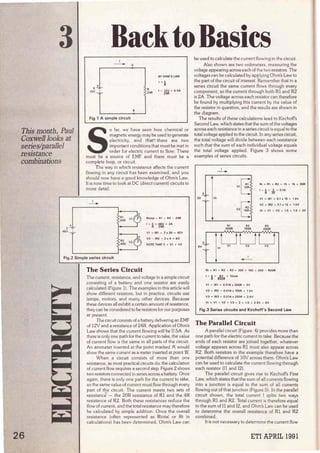
The Series Circuit
The curren!, resistance, and voltage in a simple circuí!
consisting of a battery and one resistor are easily
calculated (Figure 1). The examples in this artlcle will
show different resistors, but in practice, circuits use
lamps, motors, and many other devlces. Because
these devices ali exhibit a certain amount of resistance,
they can be considered to be resistors for our purposes
at present.
The circuit consists of a battery delivering an EMF
of 12V anda resistance of 24R. Application of Ohm's
Law shows that the curren! flowing will be 0.5A. As
there is only one path for the curren! to take, the value
of curren! flow is the same in all parts of the circuit.
An ammeter inserted at the point marked '/' would
show the same curren! as a meter inserted at point 'B'.
When a circuit consists of more than one
resistance, as most practica! circuits do. the calculation
of curren! flow requires a second step. Figure 2 shows
two resislors connected In series across a battery. Once
again, there is only one path for the current to take,
so the same value of current mus~ flow through every
part of the circuit. The current meets two sets of
resistance. - the 20R resistance of Rl and the 4R
resistance of R2. Both these resistances reduce the
flow of curren!, and the total resistance may therefore
be calculated by simple addition. Once the overall
resistance (often represented as Rtotal or Rt in
calculations) has been determined, Ohm's Law can
..__
_;..._______________
_- - - -
be used to calculate the curren! flowing in the circuit.
Also shown are two voltmeters, measuring the
voltage appearing across each of the two resistors. The
voltages can be calculated by applying Ohm's Law to
the par! of the circuí! of interest. Remember that in a
series circuí! the same curren! flows through every
componen!, so the current through both Rl and R2
is ZA. The voltage across each resistor can therefore
be found by multiplying this curren! by the value of
the resistor in question, and the results are shown in
the diagram.
The results of these calculations lead to Kirchoffs
Second Law, which states that the sum of the voltages
across each resistance in a series circult is equal to !he
total voltage applied to the circuit. In any serfés circuit,
the total voltage will divide between each resistance
such that the sum of each individual voltage equals
the total voltage applied. Figure 3 shows sorne
examples of series circuits.
±_
~
J V _j_ Vt
1
-
R1
200R
¡--;
V1L:>
. ¡:.
V2C>
R2
150R
Rt = R1 + R2 = 15 + 15 = 30R
1 = E = 3 = O1A
R 30
V1 = IR1 = 0.1 x 15 = 1.5V
V2 = IR2 = 0,1 x 15 = 1,5V
V1 = V1 + V2 = 1.5 + 1 5 = 3V
R3
250R
Rt = R1 + R2 + R3 = 200 + 150 + 250 = 600R
1 = ~ = ~ = 10mA
V1 = IR1 = 0.01A X 200R = 2V
V2 = IR2 = 0.01A x 150R = 1 SV
V3 = IR3 = o 01A X 250R = 2.sv
V1 = V1 + V2 + V3 = 2 + 1.5 + 2 SV = 6V
Fig.3 Series circuits and Kirchoff's Second Law
The Parallel Circuit
A parallel circuit (Figure. 4) provides more than
one path for the electric current to rake. Because the
ends of each resístor are joined together, whatever
voltage appears across Rl must also appear across
R2. Both resistors ín the example therefore have a
potentialdifference of 10V across them. Ohm's Law
can be used to calculate the current fJowing through
each resistor (J l and 12).
The parallel círcuit gives rise to Kirchotfs First
Law, which states thatthe sum of all currents flowing
into a junction is equal to the sum of ali currents
flowing out of that junction (Figure.5). In the paralle!
clrcuit shown. the total curren! 1 splits two ways
through Rl and R2. Total currenl is therefore equal
to the sum of ll and 1
2. and Ohm's Law can be used
to determine the overall resistance of Rl and R2
combined.
It is not necessary to determine the curren! flow
ETI APRIL 1991
2. lt
-
R1
100R
11 = ~ = iY¡'j¡ = 0 .1A l100mAI
12 • h = & = O.OSA 1
60mA)
lt ~ 11 + 12 = 100mA + 50mA = 150mA
R2
200R
Rt = ¡¡ = ~ = 66.67R !TO 2 DECIMAL PLACES!
Fig.4 Simple parallel cicuit
to calculate the total resistance, however. Figure 6
shows how Ohm's Law and Kirchoffs First Law can
be used to develop a formula for calculating parallel
resistance. This formula can be employed to calculate
the total resistance of any number of parallel resistors.
A useful point to remember is that if severa! resistors
of the same value are connected in parallel, the total
resistance is equal to the value of one resistor divided
CURRENTS FLOWING lNTO JUNCT10N:
11 + 12 + 13 = 2 + 1 + 4 " 7A
CURRENTS FLOWING AWAY FROM JUNCTION:
14 + 15 = 6 + 1 = 7A
Fig.5 Kirchoff's First Law
by the number of resistors. Two resistors of lOOR
connected in parallel, for example, give an overall
resistance of 50R. Three resistors of 30R each would
give a total resistance of lOR, and so on.
The key points to remember about series and
parallel circuits are summarized in Figure 7.
t
:~
t
!lt
Vt
"
¡
11
Rl
-
• A
-v ... .,.
1
2
A2
-
T TT
1
3
AJ
-
• A
- y ,.. ..,.
h e 11 + 12 + 13 IKIRCHOFF'S Fl~ST LAW)
11 = *t 11 e ri112 = ~ 13 = .ll!. IOHM'S LAWI
R3
BV SUBSTITUTING OHM 'S LAW EQUATIONS IN KIRCHOFF'S FIRST LAW:
*f = ri1 + ~ + ~ •'
THEREFORE:
1 = 1 + 1 + 1
Ri lfl lf2 lrn
Fig.6 Calculating parallel resistance combinations
ETI APRIL 1991
A Practica( Application
Last month it was mentioned that a micro-
ammeter is often used to measure voltages by using
a series multiplier resistance. The laws we have seen
in this part of the series are ali that are needed to
calculate such resistances, and Figure 8 shows an
example.
The meter itself registers full scale when 50µA of
current flows. The coi! has a resistance of 4000R
which because it is inside the meter movement is
called the interna! resistance of the meter (Rinternal) .
Rm represents the multiplier resistance, the value of
which must be calculated.
11
~
!·
( e 1SE.Al~ CIRCUIT
Vt = V1 + V2 + V3
11 = 11 • 12 = 13
Rt = R1 + R2 + R3
lt
--
_]_ V1
E
1b 1PARALLEL CIRCUIT
Vt = V1 = VL = V3
lt = 11 + 12 + 13
Rt = 1
12
~
lt
-
(1 /R1 1-> 1
1/R2 1+ 11/RJI
13
--
R3
i12 il3
R2E R3
Fig.7 Series/parallel circuit summary
Ohm's Law is used to determine the total
resistance that the meter and Rm mus! offer in order
that 50V at the positive and negative terminals causes
50µA of current to flow. You have learned that the total
resistance of two resistors in series is equal to their sum,
so the required válue of Rm is the difference between
the total resistance required and the interna! resistance
of the meter.Another example is shown in Figure 9,
this time using a lmA meter instead of a 50µA type.
This meter will indicate voltages up to 50V just as
effectively as the circuit of Figure 8, but there is an
important factor which gives the first circuit better
sensitivity. You have seen that when a resistance is
placed in parallel with another, the overall value of
resistance is lowered. A voltmeter using a series
multiplier resistor looks just like another resistance to
the circuit under test, so the meter's resistance can
affect the circuit be tested. The total resistance of the
first voltmeter is lMO; the resistance of the second
meter is only 50k.
Figure 10 shows how the low sensitivity of a
meter can give misleading results. Rl is a resistor in
a circuit which must be tested, and has a value of
lOOk. To measure the voltage across Rl, a meter is
clipped to each o.f its wires. The SOV meter using a
SOµA movement has a total resistance of lMO, which
is effectively placed in parallelwith Kl. This resistance
upsets the normal resistance of lOOk, and actually
results in an overall resistance of slightly under 91k.
The circuit under test should have a resistance of lOOk
between points '!:. and 'B' on the diagram, but the
presence of the meter changes this value.
27
3. 28
lfthe meter using a lmA movement is used, the
meter resistance is 50k. When Ibis is combined with
R1 the overall resistance is only 33k, or one lbird of
the value it shou.ld be. With such drastic changes to
circuit resistances, it is quite probable that the voltage
across Rl will drop much lower than its normal value,
and the meter will therefore give a mlsleadingly low
reading.
Voltmeters, being connected in parallel across
existing circuits, should therefore be designed to have
as high a resistance as possible so they do not
adversely affect the circult being tested. Voltmeter
sensitivity depends upon the FSD current rating of the
meter movement used, so the lower the current
needed for FSD the better. Sensitivity is usually
specified as so many Ohms per Volt. The 50¡.iA
movement always has a sensitivity of 20,000 Ohms
per Volt, for example. This means that a lV range on
the meter would give a total resistance of 20k, a 2V
range would have a totalmeter resistanceof 40k, and
so on. The Hgure of 20k/ V for sensitivity is typical of
SOuA FSO
~
! -1 !
+
Rm IS MULTIPLIER RESISTANCE
METER TO REAO FULL SCALE WHEN SOV APPLIEO TO TERMINALS
FOR FSO:
1 = SOuA = O.OS mA
USING OHM"S LAW, TOTAL RESISTANCE:
Rt = o.8~~A = 1.000k 11MO)
Rt = Rinternal + Rm
THEREFORE:
Rm = Rt - Rinternal = 1,0001< - 4k0 = 996k
Fig.8 Multiplier calculations for a voltmeter
rnany good multi-range meters.
The voitmeter provides a practica! dernonstration
of a simple series circult, and the arnmeter can provide
an example of a simple paraUel circuit put into practlce.
Figure 11 shows how a shunt resistance can
extend the range of an ammeter. The example shows
a lmA meter which must be converted to read
currents of up to lOmA. The meter cannot carry more
than lmA, so a resistor is shunted across so that sorne
current bypasses the meter movement. lf lmA flows
through the meter then Kirchoffs First Law tells us that
9mA must flow through Rs. In order to use Ohm's Law
to calculate the value of Rs, we must also know the
voltage that appears across !t at foil sea.le. A l mA
meter with an interna! resistance of 200R requires
0.2V for full-scale deflection, and because R, is in
1mAFSO
~
! 1 ' !
+
METER TO REAO FULL SCALE WHEN 50V APPLIEO TO TERMINALS
FOR FSO:
1 = 1mA
USING OHM 'S LAW, TOTAL RESISTANCE:
Rt =fil!.!. = SOk
1mA
Rt = Rintemal + Rm
THEREFORE:
Rm = Rt - Rinternal = 50k - 0.2k = 49.8k
Fig.9 A less sensitive voltmeter
.
L----'--------''------ - - - - - -
R1
A 100k B
(a)--<•~•----'"./VV'.._____
u~
PAIIT OF CIRCUIT
BEING TESTEO
R1
1·b1-...
~_,..g-r-~--_,.::: '
L------.J
A
R1
1 8
Fig.10 Effect of meter sensitivity
~ = 1'f + Rm!rer
¡¡.=~+~
SO. Rt ~ 90.9k
so.Rt • 33.33k
parallel the same voltage must appear there. R can
then be cakulated by dividing the voltage acros~ the
meter by the current (9mA) which must flow through
the shunt.
Because an ammeter is connected in serles with
an existing circuit, it should have as low a resistance
as possible so as not to affect the circuit under test too
much. When the meter is not connected, the two
points in the circuit are jolned together, and have a
resislance of zero ohms (oras near to zero as possible).
Any resistance in the ammeter is therefore resistance
which is not normally present, and may reduce the
current which flows in the circuit.
1inA·FSO
lt
- 11 Rlntomol =·zOOR h
- -
+o----......---1'
12
- Rs
Va
METER TO REAO 10mA AT FULL SCALE
lt = 10mA ANO 11 MUST BE 1mA
RO • SHUNT flESISTANCE
12 = lt - 11 = 10mA - 1mA = 9mA CKIRCHOFF'S SECONO LAWI
Vt = 11 Rinternal = 1m Ax 200R = OV2 (OHM'S LAW)
FROM OHM'S LAW:
Rs =19 = ~ =22.22R (TO 2 DECIMAL PLACES)
Fig.11 Shunt resistance calculations for ammeters
Series and Parallel Combinations
Most circuits do not conveniently fall into a simple
series or parallel category, and consist of many
branches of each type. Figure 12 shows a simple
combination.
The key to ca.lculations in such combination
circuits it to analyse each section of the circuí!
separately, Start with the parallel combination of R2
and R3. lf we call their combined resistance Rx, the
parallel resistance formula can be used to give an
overall value of600R. The parallel branch has now
been simplified, and the circuit becomes Rx (value
600R) in series with Rl (value 400) . The total
resistance is therefore 1,000R.
ETI APRIL 1991
4. ,, fil
- 400R
r-- ----,
R• 1
1
+
l1i
~t
il2 1
_l!v
1 1
RZ Rl
1 1k0 11t6
1
1
1
1
L ______...J
CALLCO!lllllNEt> RESISTANCE AT R21R3 A•
, ....l. + 1 _L + _l_
lli; fl2 lrn 1lilr 1Ji5
lb . 60011
R1a1al ~ fil • R1 = 600R • 400R " l kO
11 ~ ~ 9mA
VOl.TAGE V>< = lt • 1111 - 9mJI. • 600R = 6.411
,, = 11 . 12
SO, 12. • lt - 11 ~ 9mA - S.4mA • 3 8mA
Flg.12 Series/Parallel combinatlons
With the total resistance known, 1
101
ª1
can be
calculated (9mA) _Suppose that the curren! through
each of the resistors R2 and R3 needs to be
determined. We know that the 9mA of (1
must split
between 11 and !2. lf we call the voltage across the
resistors Vx, Ohm's Law can be used to calculate this
voltage from the total current 11
, and the parallel
resistance, Rx. lt is then a simple matter to calculate
the value of 11, as shown. The value of !2 must be the
difference between the total current and ll (Kirchoffs
First Law). The same results could have been
achieved by using Ohm's Law to calculate 12 and then
taking 12 from the total current to give 11. In rnany
prnctical circuits you will find that there are severa!
routes to the same answer. These examples
emphasize the importance of learning the basic
electrical laws, particularly Ohm's Law.
POWER VOLTAGE a CIJRR~
SO VOLTll-GE ~ AND CURR~T =~
lfT E • VOLTAGE, 1= CURRE1IT, ANO P = POWEll IN WATTS
P • laE l=-r E 1f
F19.13 Calculation of power
Power
So far, you have been dealing with three main
electrical quantities: voltage, curren!, and resistance.
Power is the actual amount of work that is done in
moving electrons along a conductor. Much power is
dissipated as heat, sometimes intentionally as in an
electric fire. The primary purpose of a lamp is to give
off light, but it also radiates a certain amount of heat.
However, the power is consumed, be it light, heat or
motion, it is measured in Watts (written as the symbol
'W') and is directly proportional to both the voltage
and the curren! flowing in a particular circuit. The
formula used for calculating power is very similar to
ETI APRIL 1991
that used for Ohm's Law, anda triangle arrangement
may be used to aid calculations (Figure 13). Justas
with Ohm's Law, the formula may be applied to an
entire circuit or just a section of it. Figure 14 shows
how to go about calculating the power dissipated by
a circuit.
By rearranging the formula it is possible to
calculate voltage or current when given the power.
The curren! drawn by a 48-watt, 12-volt bulb, for
example, may be calculated by dividing the power by
the voltage (the answer is 4A).
lt is importan! to be able to calculate the power
dissipated by each part of a circuit, for many
components can only handle a certain amount of
power. lf that power rating is exceeded, the
componen! overheats and may be damaged.
In Figure 14b the resistance of the bulb was
known, but not the amount of curren! of passing
through it. The power triangle requires voltage and
current to be known. By simple formula
rearrangement it is possible to write two further
formulae (Figure 15) to aid calculations. Power can
be calculated directly so long as two out of three
quantities (current, voltage, and resistance) are
known. Try the new formulae in the examples and
confirm that the answers are the same. Note that in
a circuit with constan! resistance, if the supply voltage
is doubled the power is quadrupled, because the
current is also doubled.
Next month we examine AC clrcuits and
phase.
1 = 0.5A
(a)
1t Al
- 11111
t V1
Ptotal = Ex lt = 6V x 0.25A = 1.5W
V1 = ltA1 = 0.2511- X 18A = 4V5
P= l aE
P • O.l>A 13V
LP1 1.6W
LET RL a RESISTANCE OF l.AMP
Rt • R1 +Rl • 18 + 6 • 24R
LP1
IRL • SRI
SO POWEA DISSIPATED BY R1 = ltV1 = 0.25A x 4V5 = 1.125W
ANO POWEA DISSIPATED BY LP1 = 1t x IVt - V11 = 0,25A x 1V5 =
O, 375W
NOTE THAT Ptotal = PinR1 + PinlP1
Fig.14 Power combinations in simple circuits
P = 1x E
OHM'S LAW PROVES THAT 1 = E', SO BY SUBSTITUTION;
R
P=-"xEORP=~
R R
OHM'S LAW ALSO SHOWS THAT E = 1x R. SO BY SUBSTITUTION:
P = lxll x RI DR P = l'R
Fig.15 Sorne more power formulae
29
5. DesigninganElectronic
2
l]ohn Smith now tums
the circuit design into
a working voltmeter
46
1
TestMeter r-~l !
¡,¡}¡
L
as! month, a final design was produced for
an active multi voltmeter. Now we turn our
attention to the construction, but just
befare that you'll notice that Figure 1 shows
the full theoretical circuit with the inclusion
of the range resistors, and the various FSD inputs.
Rmsh is placed across the meter and its value will
depend on the meter type - more of that later.
Construction
Referring to the view shown in Figure 2, looking into
the rear of the Plastic Box. Make board 'Pi. from plain
copper-clad PC material, with the copper on the
4
l/Ps R104e 10M
R104d lOM
10M
10M
10M
3
R103f
6MB
6MB
R4
24l<
12
RVl
2k2
R101 1MO
6
. ··-
upper stirface. Cut a 'U' notch in the centre of the
lower edge as shown in Figure 3. Check that this board
is a snug fit into the lower par! of the plastic box. Cut
board 'B' as with board '/>:. to make a 'U' notch in the
centre of the lower edge. Align the two boards and
ensure that the excess width of board '/>:. is equally
13mm either side of board 'B'.
lf this is satisfactory, mark and dril! the two 6 BA
holes through board W Again with board '/>:., dril! the
3mm holes for the switch mounting, and cut the slot
for the switch 'tarig'.
Assemble the two boards, using 6 BA bolts and
spacers and then add the switch, using 3mm bolts,
SW1
ON--OFF
o--o--0 • 1vs
1
1
B+ 1
TEST !
POINT 1
1
1
1
C1 1
1500p J
R3b SOuA 1
lOOR 1
GNO 1 OV
1
1
05
R6 C2 1
2k2 1&00p
1
1
1
~ - 1V5
-
VE COMMON NEGATIVE INPUT Fig. 1 Full circuit of testmeter.
ETI APRIL 1991
--~- -- ~- --L_ _:__ _ _ _ _ _~----------~~-~---
6. to see that everything is fitting so far.
Dismantle and make the 5mm holes in board 'PI.
for the sockets, being careful with alignment, as the
appearance of the completed instrument will be
affected by this. Still with board 'P., countersink the 6
BA and the 3mm holes on the plain side.
Mount RVl on the copper side of board 'B', so
that it is a little less than 6mm proud, and set exactly
along the centre-line of the board.
Drill a pilot hole in board 'PI. to coincide with
adjusting slot of RVl. Assemble the two boards and
check that this hole will give access to RVl. If this is
satisfactory, enlarge this hole. Complete the work on
board 'B', noting that R1
b and R3
b are mounted on the
copper side, for convenience.
Also fit and solder the !C. the chip contains only
normal silicon transistors so, although care must be
taken, it is not so easy to damage as a FET. The IC
may be mounted on a holder. if desired.
Leave ali outgoing leads over-length.
Using board 'PI. as a template, make the 5mm
holes, the slot for the switch 'tang', and the access hole
for RVl in the front panel of the Plastic Case.
DO NOT DRILL THE 6 B.A. OR THE 3mm
HOLES THROUGH THE FRONT PANEL. The
large hole, and the four small (2.5mm) holes for the
meter may now be made. Check that the dimensions
in Figure 2 agree with the information given with the
meter. Also check that the meter will fit between the
top of board 'PI. and the protruding plastic moulding
al the top of the box.
If ali is well so far, the meter may be fitted and
held in place with the 2.5 mm nuts and washers
supplied.
Fit spacers and switch to board 'P., remernbering
to use the shortened c/ s bolts for the spacers. Wire
the switch as shown in detail in Figure 5, fitting Cl and
C2 from the ± terminals of the switch to the copper
surface of board 'PI.. Select the value of Rmsh from the
chart in Figure 6 and solder the resistor(s) directly to
the meter terminal tags, this will convert any meter to
one of lmA full scale. Connect the ± meter leads from
board 'B'.
Fit board 'PI. into lower part of the case, holding
it in with the socket locking nuts. Fit board 'B' on to
spacers.
ETI APRIL 1991
13mm
Smm
~
o
Jmm
1 1
1 1
.."'
t
SLOT FOR
SW 'TANG'
BOARD 'B'
FOUR HOLES
2.5mm
METER
HORIZONTAL
Cl
r-¡1·
1 1
L_J
MINIATURE
SWITCH
BOARD 'A' COPPER
PC BOARD
COPPER THIS SIDE
o -$-sBA
Fig. 2 Detail inside box.
Check that the switch is OFF and temporarily
connect the battery, noting that the 'O' volts wire
should go between the two cells.
Switch on, and see that the meter can be zeroed
by RVl, then apply 3 or 4.5 volts to input two.
(Remember that a new alkaline cell will give more than
1.5 volts.) The reading obtained should be accurate
to 1%, but if a check meter is available - so much
the better!
Ifthings are not going too well at this stage, switch
OFF, disconnect the battery, and check:
That the i.c. is the right way round. (!)
That the correct value components are in the
corree! places.
Ifthe instrument works, but the ranges are badly
in error, check that Rmsh is the corree! value for the
meter in use, and that the high value range resistors
are right - high value colour codes can be confusing!
Assuming that a!l is now OK, check that the
battery box will fit in the comer of the lid, without the
6.Smm
~mm
jul·-
Dl14mm
-$Jmm
Cl
68Afl
DISTANc~
·x·
APPROX 18mm
REFER TO NOTES
68A
8.5mm
75mm·~-
~m
l5mm
+
•c~NTHIS SIDE
7
mmT 7mm
--~~~~~-'-~~-
Fíg. 3 Board 'A' detall viewed from rear of plas'tic box.
47
7. 48
OV
-
M l ~
QQ o
lfl LflNOTCH TO
FIT ~ox
+1V5 +- 1VS
-1V5 - 1V5
Fig. 4 Component Overlay for Testmeter.
11116 ov RV1
R3a
R1a 100R
C3 R2 100k R4
INPUT$
1VO
5VO
sov
100V
JJOp 47k 24k
llP
6 3
o3 b3 c2 •11
e2
IC1
c3 b4 e4 c4 bS a6/sub c6
8 9 10 11 12 13 14
MI "'
RV1
R6 A6 NOTE;
2k2 2k2 IC1 • CAJ046
·"1 V5 - 1V5 + 1VS - 1V5
Fig. 5 IC wiring detail.
lON
Fig. 6 Switch wiring detail.
Fig. 7
- - - - - - 1V5 TO B BOX
- - - - - 1V5
COPPEA FACE
.r----.. OF BOARD 'A'
Values of metershunt resistors Rmsh for various meter movements.
Panel Meter Full Scale Interna! Shunt for Made from Two
Maplin Code Current Resistance 1mA Resistors in
Parallel.
FM 98G 50uA 4300R 226.3R 910 &300R
RW 92A 100 uA 3750R 416.7R 1600 &560R
RW94C 1mA 200R not req. -- --
metal cases of the cells touching any components, or
exposed wfring, and then stick the battery box1n place.
Make the baitery connections uslngo solder tag under
lhespnrigin the batterybox - be carefullhalthis t:ag
doesn'ttolJch anythlng else.Fix theJid w!th thescrews
provided - if you haven't lost them - and away you
go !
The instrument only take about l1/2 mA
quiescent, to 2V2mA full scale - so you shouldn't
need to change the batteries very often . A battery
check socket has been provided, if the volts fall much
below 1.Sv., change both cells.
Values of meter shunt resistors R msh for various meter
movements.
PARTS LIST _ _ ___ _
" "
RESISTORS - Metal Film - 1%
R1 50k lor R1a, R1b - 100k each)
R2 47k
R3 50R lor R3a, R3b - 100R each
R4 24k
R5 2.2k
R6 2.2k
RANGE RESISTORS
R101
R102a, 102b
R103a,e, e
R103b, d,f
R104, ato e
AV1
Rmsh
CAPACITORS
C1,2
C3
SEMICONDUCTORS
IC
. MISCELLANEOUS
1M
10M
6.8M
8.2M
10M
2k2 horiz preset
Value depends on meter used (seeTable)
1,500p
330p
CA3046
Box !Wh~el. Me(er 150 uA).. Switch (Double Polel. Skts 2mm RED,
BLACK Battery Holder
Copp~r Board
6BA Tapped Spacers
6BA c/sBolts
6BA Rnd. Head
M3 c/s Bolts
Connecting wire
71x60mm
IY4 inchl
1Y4 inch)
rn inchl
16mml
Solder tag - about 6BA - for extra battery connection.
Two A.A.A. cells - Alkaline preterred.
. Set of Test·Prods wíth 2mm, Plugs.
------..··~---~
• 1
![lt
-
R1
100R
11 = ~ = iY¡'j¡ = 0 .1A l100mAI
12 • h = & = O.OSA 1
60mA)
lt ~ 11 + 12 = 100mA + 50mA = 150mA
R2
200R
Rt = ¡¡ = ~ = 66.67R !TO 2 DECIMAL PLACES!
Fig.4 Simple parallel cicuit
to calculate the total resistance, however. Figure 6
shows how Ohm's Law and Kirchoffs First Law can
be used to develop a formula for calculating parallel
resistance. This formula can be employed to calculate
the total resistance of any number of parallel resistors.
A useful point to remember is that if severa! resistors
of the same value are connected in parallel, the total
resistance is equal to the value of one resistor divided
CURRENTS FLOWING lNTO JUNCT10N:
11 + 12 + 13 = 2 + 1 + 4 " 7A
CURRENTS FLOWING AWAY FROM JUNCTION:
14 + 15 = 6 + 1 = 7A
Fig.5 Kirchoff's First Law
by the number of resistors. Two resistors of lOOR
connected in parallel, for example, give an overall
resistance of 50R. Three resistors of 30R each would
give a total resistance of lOR, and so on.
The key points to remember about series and
parallel circuits are summarized in Figure 7.
t
:~
t
!lt
Vt
"
¡
11
Rl
-
• A
-v ... .,.
1
2
A2
-
T TT
1
3
AJ
-
• A
- y ,.. ..,.
h e 11 + 12 + 13 IKIRCHOFF'S Fl~ST LAW)
11 = *t 11 e ri112 = ~ 13 = .ll!. IOHM'S LAWI
R3
BV SUBSTITUTING OHM 'S LAW EQUATIONS IN KIRCHOFF'S FIRST LAW:
*f = ri1 + ~ + ~ •'
THEREFORE:
1 = 1 + 1 + 1
Ri lfl lf2 lrn
Fig.6 Calculating parallel resistance combinations
ETI APRIL 1991
A Practica( Application
Last month it was mentioned that a micro-
ammeter is often used to measure voltages by using
a series multiplier resistance. The laws we have seen
in this part of the series are ali that are needed to
calculate such resistances, and Figure 8 shows an
example.
The meter itself registers full scale when 50µA of
current flows. The coi! has a resistance of 4000R
which because it is inside the meter movement is
called the interna! resistance of the meter (Rinternal) .
Rm represents the multiplier resistance, the value of
which must be calculated.
11
~
!·
( e 1SE.Al~ CIRCUIT
Vt = V1 + V2 + V3
11 = 11 • 12 = 13
Rt = R1 + R2 + R3
lt
--
_]_ V1
E
1b 1PARALLEL CIRCUIT
Vt = V1 = VL = V3
lt = 11 + 12 + 13
Rt = 1
12
~
lt
-
(1 /R1 1-> 1
1/R2 1+ 11/RJI
13
--
R3
i12 il3
R2E R3
Fig.7 Series/parallel circuit summary
Ohm's Law is used to determine the total
resistance that the meter and Rm mus! offer in order
that 50V at the positive and negative terminals causes
50µA of current to flow. You have learned that the total
resistance of two resistors in series is equal to their sum,
so the required válue of Rm is the difference between
the total resistance required and the interna! resistance
of the meter.Another example is shown in Figure 9,
this time using a lmA meter instead of a 50µA type.
This meter will indicate voltages up to 50V just as
effectively as the circuit of Figure 8, but there is an
important factor which gives the first circuit better
sensitivity. You have seen that when a resistance is
placed in parallel with another, the overall value of
resistance is lowered. A voltmeter using a series
multiplier resistor looks just like another resistance to
the circuit under test, so the meter's resistance can
affect the circuit be tested. The total resistance of the
first voltmeter is lMO; the resistance of the second
meter is only 50k.
Figure 10 shows how the low sensitivity of a
meter can give misleading results. Rl is a resistor in
a circuit which must be tested, and has a value of
lOOk. To measure the voltage across Rl, a meter is
clipped to each o.f its wires. The SOV meter using a
SOµA movement has a total resistance of lMO, which
is effectively placed in parallelwith Kl. This resistance
upsets the normal resistance of lOOk, and actually
results in an overall resistance of slightly under 91k.
The circuit under test should have a resistance of lOOk
between points '!:. and 'B' on the diagram, but the
presence of the meter changes this value.
27](data:image/gif;base64,R0lGODlhAQABAIAAAAAAAP///yH5BAEAAAAALAAAAAABAAEAAAIBRAA7)