The OMG Application Instrumentation Specification provides a simple way to instrument applications so that their internal state can be accessed by remote applications and tools in order to supervise the correct operation of the system. All this with minimal impact on the application so that it can be used even within real-time threads. The Application Instrumentation API is available in C and Java.
This specification was adopted (in Beta form) by the OMG in September 2013
Draft submission to the OMG RPC over DDS RPF.
This draft standard defines a Remote Procedure Call (RPC) framework using the basic building blocks of DDS, such as topics, types, and entities (e.g., DataReader, DataWriter) to provide request/reply semantics. It defines distributed services, characterized by a service interface, which serves as a shareable contract between service provider and a service consumer. It supports synchronous and asynchronous method invocation.
NOTE: This document has been obsoleted by the Adopted DDS Specification
OMG DDS Security Draft Specification. This is the 5th Revised Submission to the DDS Security Specification.
Also accessible from the OMG at:
http://www.omg.org/members/cgi-bin/doc?mars/13-05-17.pdf
This is the DDS Security adopted specification.
It was adopted as an OMG standard in June 2014.
The official URL is http://www.omg.org/spec/DDS-SECURITY/
NOTE: This document has been obsoleted by the Adopted DDS Specification
OMG DDS Security Draft Specification. This is the 4th Revised Submission to the DDS Security Specification.
Also accessible from the OMG at:
http://www.omg.org/members/cgi-bin/doc?mars/13-02-15.pdf
NOTE: This document has been obsoleted by the Adopted DDS Specification
This is the September 2013 Draft Submission to the OMG DDS Security Specification
This is the DDS-XRCE 1.0 Beta specification adopted by the OMG March 2018.
The purpose of DDS-XRCE is to enable resource-constrained devices to participate in DDS communication, while at the same time allowing those devices to be disconnected for long periods of time but still be discoverable by other DDS applications.
DDS-XRCE defines a wire protocol, the DDS-XRCE protocol, to be used between an XRCE Client and XRCE Agent. The XRCE Agent is a DDS Participant in the DDS Global Data Space. The DDS-XRCE protocol allows the client to use the XRCE Agent as a proxy in order to produce and consume data in the DDS Global Data Space.
Revised submission for Unified Component Model (UCM) for Distributed, Real-Ti...Remedy IT
Remedy IT revised submission for the Unified Component Model (UCM) for Distributed, Real-Time and Embedded Systems.
Change of address Remedy IT:
Melkrijder 11
3861 SG Nijkerk
tel. +31 (0)88 053 0000
This document specifies the OMG Interface Definition Language (IDL). IDL is a descriptive language used to define data types and interfaces in a way that is independent of the programming language or operating system/processor platform.
The IDL specifies only the syntax used to define the data types and interfaces. It is normally used in connection with other specifications that further define how these types/interfaces are utilized in specific contexts and platforms.
This specification is a response to the OMG RFP "eXtremely Resource Constrained Environments DDS (DDS- XRCE)"
It defines a DDS-XRCE Service based on a client-server protocol between a resource constrained, low-powered device (client) and an Agent (the server) that enables the device to communicate with a DDS network and publish and subscribe to topics in a DDS domain. The specifications purpose and scope is to ensure that applications based on different vendor’ implementations of the DDS-XRCE Service are compatible and interoperable.
This is the Joint submission by RTI, TwinOaks, and eProsima. Updated September 2017, OMG document number mars/2017-09-18.
This publication is intended for administrators tasked with deploying an Imperva SecureSphere in an Amazon Web Services (AWS) environment. It assumes the reader has a working knowledge of AWS and details the configuration steps required to achieve a successful deployment.
The primary goal of TR-398 is to provide a set of test cases and framework to verify the performance
between Access Point (AP) (e.g., a CPE with Wi-Fi) and one or more Station (STA) (e.g., Personal Computer
[PC], integrated testing equipment, etc.). The test cases are defined for a Device Under Test (DUT – AP only),
tested against a or a set of STA.
Conférence Laboratoire des Mondes Virtuels_Be Tomorrow_Data mining with Phoen...Johan-André Jeanville
Capital Games organise une conférence le mercredi 22 mai, de 9h à 17h au Centre de Conférences de Microsoft, à Issy-les-Moulineaux. Elle permettra aux professionnels du jeu vidéo de monter en compétences sur les nouvelles méthodes de production de jeux connectés, parmi lesquelles l'analyse de données.
Présentation de la solution de Data Mining dédiée au jeu vidéo: Phoenix par Be Tomorrow.
Especial World Travel Market Hosteltur 2010Hosteltur
WTM es una de las ferias turísticas más importantes del mundo, tiene lugar en Londres del 9 al 12 de Noviembre , y por esta razón, anualmente editamos un número dirigido específicamente al agente de viaje británico, con una información amplia y detallada de España como destino para las turistas del Reino Unido. En el tratamos desde los resultados de temporada hasta las nuevas tendencias turísticas. Desde el sol y playa, hasta el turismo de Congresos y la gastronomía. Un informe detallado que llegará directamente a las empresas que más turismo venden para España.
Reasons for the Popularity of Medical Record TheftOPSWAT
After a slew of data breaches in 2014, the FBI warned the healthcare industry that cyber-criminals would be directing more attention their way in 2015. The healthcare industry has become an increasingly valuable target for cyber thieves, and in some cases, a much easier target to attack, due to their often less than adequate investment in cyber security. What is it about the healthcare industry that has captured the cyber criminals' interest in the last few years?
This white paper covers various topics including industry data breach statistics, the value of credit card data versus medical record data, healthcare spending on cyber security and the impact of BYOD on industry vulnerability to data breaches. This white paper also highlights various solutions for protecting medical record data including multi-scanning, email security and the protection of endpoint devices.
Get an overview of Microsoft PowerApps, still in preview, and learn how to build your first PowerApp by connecting to SharePoint Online. For a full recording of the presentation, visit it on YouTube at https://www.youtube.com/watch?v=T6fxBgLoxqc
Digitální exportní akademie - Den 3 - Google AnalyticsSun Marketing
Naše část přednáškového programu třetího dne Digitální exportní akademie, pořádané ve spolupráci Google a CzechTrade. Představení Google Analytics a možnosti jejich praktického využití pro exportně orientované klienty.
The Mall is Dead: Who Killed It, Why It's Not Coming Back and What's Next for...Suong Nguyen
The Mall is Dead, the second SlideShare in a series exploring the future of retail from North American Properties - Atlanta (NAP), examines the decline of malls and how the hottest retail and restaurant concepts are increasingly choosing walkable, urban mixed-use locations instead of malls.
The first SlideShare in The Future of Retail series, “The Secret Sauce: Why Retail and Mixed-Use Projects Need Local Chefs,” was launched at the International Council of Shopping Centers (ICSC) RECon Convention in Las Vegas last month.
This the the formal version 1.0 of the DDS Security specification released September 2016. OMG document number formal/2016-08-01.
DDS-Security defines the Security Model and Service Plugin Interface (SPI) architecture for compliant DDS implementations.
The DDS Security Model is enforced by the invocation of these SPIs by the DDS implementation. This specification also defines a set of builtin implementations of these SPIs.
* The specified builtin SPI implementations enable out-of-the box security and interoperability between compliant DDS applications.
* The use of SPIs allows DDS users to customize the behavior and technologies that the DDS implementations use for Information Assurance, specifically customization of Authentication, Access Control, Encryption, Message Authentication, Digital Signing, Logging and Data Tagging.
This is the Beta 1 version of the OPC UA / DDS Gateway specification released by the Object Management Group in March 2018.
This specification defines a standard, vendor-independent, configurable gateway that enables interoperability and information exchange between systems that use DDS and systems that use OPC UA.
Data Distribution Service (DDS) is a family of standards from the Object Management Group (OMG) that provide connectivity, interoperability, and portability for Industrial Internet, cyber-physical, and mission-critical applications.
The DDS connectivity standards cover Publish-Subscribe (DDS), Service Invocation (DDS-RPC), Interoperability (DDS-RTPS), Information Modeling (DDS-XTYPES), Security (DDS-SECURITY), as well as programing APIs for C, C++, Java and other languages.
The OPC Unified Architecture (OPC UA) is an information exchange standard for Industrial Automation and related systems created by the OPC Foundation. The OPC UA standard provides an Addressing and Information Model for Data Access, Alarms, and Service invocation layered over multiple transport-level protocols such as Binary TCP and Web-Services.
DDS and OPC UA exhibit significant deployment similarities:
• Both enable independently developed applications to interoperate even when those applications come from different vendors, use different programming languages, or run on different platforms and operating systems.
• Both have significant traction within Industrial Automation systems.
• Both define standard protocols built on top of the TCP/ UDP/IP Internet stacks.
The two technologies may coexist within the same application domains; however, while there are solutions that bridge between DDS and OPC UA, these are based on custom mappings and cannot be relied to work across vendors and products.
This specification provides the following additional facilities to DDS [DDS] implementations and users:
* Type System. The specification defines a model of the data types that can be used for DDS Topics. The type system is formally defined using UML. The Type System is de- fined in section 7.2 and its subsections. The structural model of this system is defined in the Type System Model in section 7.2.2. The framework under which types can be modi- fied over time is summarized in section 7.2.3, “Type Extensibility and Mutability.” The concrete rules under which the concepts from 7.2.2 and 7.2.3 come together to define compatibility in the face of such modifications are defined in section 7.2.4, “Type Com- patibility.”
* Type Representations. The specification defines the ways in which types described by the Type System may be externalized such that they can be stored in a file or communi- cated over a network. The specification adds additional Type Representations beyond the
DDS-XTypes version 1.2 1
one (IDL [IDL41]) already implied by the DDS specification. Several Type Representa- tions are specified in the subsections of section 7.3. These include IDL (7.3.1), XML (7.3.2), XML Schema (XSD) (7.3.3), and TypeObject (7.3.4).
* Data Representation. The specification defines multiple ways in which objects of the types defined by the Type System may be externalized such that they can be stored in a file or communicated over a network. (This is also commonly referred as “data serializa- tion” or “data marshaling.”) The specification extends and generalizes the mechanisms already defined by the DDS Interoperability specification [RTPS]. The specification in- cludes Data Representations that support data type evolution, that is, allow a data type to change in certain well-defined ways without breaking communication. Two Data Repre- sentations are specified in the subsections of section 7.4. These are Extended CDR (7.4.1, 7.4.2, and 7.4.3) and XML (7.4.4).
* Language Binding. The specification defines multiple ways in which applications can access the state of objects defined by the Type System. The submission extends and gen- eralizes the mechanism currently implied by the DDS specification (“Plain Language Binding”) and adds a Dynamic Language Binding that allows application to access data without compile-time knowledge of its type. The specification also defines an API to de- fine and manipulate data types programmatically. Two Language Bindings are specified in the subsections of section 7.5. These are the Plain Language Binding and the Dynamic Language Binding.
AXCIOMA, the internals, the component framework for distributed, real-time, a...Remedy IT
This presentation was previously posted as CIAOX11 but has been updated to with the latest information about AXCIOMA, the component framework for distributed, real-time, and embedded systems
AXCIOMA, the component framework for distributed, real-time and embedded systemsRemedy IT
This AXCIOMA presentation gives a high level overview of the features and capabilities of AXCIOMA, the component framework for distributed, real-time and embedded systems. AXCIOMAs roadmap includes support for the upcoming Unified Component Model (UCM) standard from the Object Management Group (OMG)
Unified Component Model for Distributed, Real- Time and Embedded Systems Requ...Remedy IT
The objective of this RFP is to solicit proposals for a new component model called the “Unified Component Model” targeting Distributed, Real-Time and Embedded (DRTE) Systems. A component model defines a set of standards for component implementation, naming, interoperability, customization, composition, evolution, and deployment.
The UCM will be a simple, lightweight, middleware-agnostic, and flexible component model. The UCM will allow many different interaction models, including publish-subscribe and request-reply.
Epistemic Interaction - tuning interfaces to provide information for AI supportAlan Dix
Paper presented at SYNERGY workshop at AVI 2024, Genoa, Italy. 3rd June 2024
https://alandix.com/academic/papers/synergy2024-epistemic/
As machine learning integrates deeper into human-computer interactions, the concept of epistemic interaction emerges, aiming to refine these interactions to enhance system adaptability. This approach encourages minor, intentional adjustments in user behaviour to enrich the data available for system learning. This paper introduces epistemic interaction within the context of human-system communication, illustrating how deliberate interaction design can improve system understanding and adaptation. Through concrete examples, we demonstrate the potential of epistemic interaction to significantly advance human-computer interaction by leveraging intuitive human communication strategies to inform system design and functionality, offering a novel pathway for enriching user-system engagements.
Maruthi Prithivirajan, Head of ASEAN & IN Solution Architecture, Neo4j
Get an inside look at the latest Neo4j innovations that enable relationship-driven intelligence at scale. Learn more about the newest cloud integrations and product enhancements that make Neo4j an essential choice for developers building apps with interconnected data and generative AI.
GDG Cloud Southlake #33: Boule & Rebala: Effective AppSec in SDLC using Deplo...James Anderson
Effective Application Security in Software Delivery lifecycle using Deployment Firewall and DBOM
The modern software delivery process (or the CI/CD process) includes many tools, distributed teams, open-source code, and cloud platforms. Constant focus on speed to release software to market, along with the traditional slow and manual security checks has caused gaps in continuous security as an important piece in the software supply chain. Today organizations feel more susceptible to external and internal cyber threats due to the vast attack surface in their applications supply chain and the lack of end-to-end governance and risk management.
The software team must secure its software delivery process to avoid vulnerability and security breaches. This needs to be achieved with existing tool chains and without extensive rework of the delivery processes. This talk will present strategies and techniques for providing visibility into the true risk of the existing vulnerabilities, preventing the introduction of security issues in the software, resolving vulnerabilities in production environments quickly, and capturing the deployment bill of materials (DBOM).
Speakers:
Bob Boule
Robert Boule is a technology enthusiast with PASSION for technology and making things work along with a knack for helping others understand how things work. He comes with around 20 years of solution engineering experience in application security, software continuous delivery, and SaaS platforms. He is known for his dynamic presentations in CI/CD and application security integrated in software delivery lifecycle.
Gopinath Rebala
Gopinath Rebala is the CTO of OpsMx, where he has overall responsibility for the machine learning and data processing architectures for Secure Software Delivery. Gopi also has a strong connection with our customers, leading design and architecture for strategic implementations. Gopi is a frequent speaker and well-known leader in continuous delivery and integrating security into software delivery.
A tale of scale & speed: How the US Navy is enabling software delivery from l...sonjaschweigert1
Rapid and secure feature delivery is a goal across every application team and every branch of the DoD. The Navy’s DevSecOps platform, Party Barge, has achieved:
- Reduction in onboarding time from 5 weeks to 1 day
- Improved developer experience and productivity through actionable findings and reduction of false positives
- Maintenance of superior security standards and inherent policy enforcement with Authorization to Operate (ATO)
Development teams can ship efficiently and ensure applications are cyber ready for Navy Authorizing Officials (AOs). In this webinar, Sigma Defense and Anchore will give attendees a look behind the scenes and demo secure pipeline automation and security artifacts that speed up application ATO and time to production.
We will cover:
- How to remove silos in DevSecOps
- How to build efficient development pipeline roles and component templates
- How to deliver security artifacts that matter for ATO’s (SBOMs, vulnerability reports, and policy evidence)
- How to streamline operations with automated policy checks on container images
Alt. GDG Cloud Southlake #33: Boule & Rebala: Effective AppSec in SDLC using ...James Anderson
Effective Application Security in Software Delivery lifecycle using Deployment Firewall and DBOM
The modern software delivery process (or the CI/CD process) includes many tools, distributed teams, open-source code, and cloud platforms. Constant focus on speed to release software to market, along with the traditional slow and manual security checks has caused gaps in continuous security as an important piece in the software supply chain. Today organizations feel more susceptible to external and internal cyber threats due to the vast attack surface in their applications supply chain and the lack of end-to-end governance and risk management.
The software team must secure its software delivery process to avoid vulnerability and security breaches. This needs to be achieved with existing tool chains and without extensive rework of the delivery processes. This talk will present strategies and techniques for providing visibility into the true risk of the existing vulnerabilities, preventing the introduction of security issues in the software, resolving vulnerabilities in production environments quickly, and capturing the deployment bill of materials (DBOM).
Speakers:
Bob Boule
Robert Boule is a technology enthusiast with PASSION for technology and making things work along with a knack for helping others understand how things work. He comes with around 20 years of solution engineering experience in application security, software continuous delivery, and SaaS platforms. He is known for his dynamic presentations in CI/CD and application security integrated in software delivery lifecycle.
Gopinath Rebala
Gopinath Rebala is the CTO of OpsMx, where he has overall responsibility for the machine learning and data processing architectures for Secure Software Delivery. Gopi also has a strong connection with our customers, leading design and architecture for strategic implementations. Gopi is a frequent speaker and well-known leader in continuous delivery and integrating security into software delivery.
Full-RAG: A modern architecture for hyper-personalizationZilliz
Mike Del Balso, CEO & Co-Founder at Tecton, presents "Full RAG," a novel approach to AI recommendation systems, aiming to push beyond the limitations of traditional models through a deep integration of contextual insights and real-time data, leveraging the Retrieval-Augmented Generation architecture. This talk will outline Full RAG's potential to significantly enhance personalization, address engineering challenges such as data management and model training, and introduce data enrichment with reranking as a key solution. Attendees will gain crucial insights into the importance of hyperpersonalization in AI, the capabilities of Full RAG for advanced personalization, and strategies for managing complex data integrations for deploying cutting-edge AI solutions.
Unlocking Productivity: Leveraging the Potential of Copilot in Microsoft 365, a presentation by Christoforos Vlachos, Senior Solutions Manager – Modern Workplace, Uni Systems
Climate Impact of Software Testing at Nordic Testing DaysKari Kakkonen
My slides at Nordic Testing Days 6.6.2024
Climate impact / sustainability of software testing discussed on the talk. ICT and testing must carry their part of global responsibility to help with the climat warming. We can minimize the carbon footprint but we can also have a carbon handprint, a positive impact on the climate. Quality characteristics can be added with sustainability, and then measured continuously. Test environments can be used less, and in smaller scale and on demand. Test techniques can be used in optimizing or minimizing number of tests. Test automation can be used to speed up testing.
How to Get CNIC Information System with Paksim Ga.pptxdanishmna97
Pakdata Cf is a groundbreaking system designed to streamline and facilitate access to CNIC information. This innovative platform leverages advanced technology to provide users with efficient and secure access to their CNIC details.
Why You Should Replace Windows 11 with Nitrux Linux 3.5.0 for enhanced perfor...SOFTTECHHUB
The choice of an operating system plays a pivotal role in shaping our computing experience. For decades, Microsoft's Windows has dominated the market, offering a familiar and widely adopted platform for personal and professional use. However, as technological advancements continue to push the boundaries of innovation, alternative operating systems have emerged, challenging the status quo and offering users a fresh perspective on computing.
One such alternative that has garnered significant attention and acclaim is Nitrux Linux 3.5.0, a sleek, powerful, and user-friendly Linux distribution that promises to redefine the way we interact with our devices. With its focus on performance, security, and customization, Nitrux Linux presents a compelling case for those seeking to break free from the constraints of proprietary software and embrace the freedom and flexibility of open-source computing.
Dr. Sean Tan, Head of Data Science, Changi Airport Group
Discover how Changi Airport Group (CAG) leverages graph technologies and generative AI to revolutionize their search capabilities. This session delves into the unique search needs of CAG’s diverse passengers and customers, showcasing how graph data structures enhance the accuracy and relevance of AI-generated search results, mitigating the risk of “hallucinations” and improving the overall customer journey.
DevOps and Testing slides at DASA ConnectKari Kakkonen
My and Rik Marselis slides at 30.5.2024 DASA Connect conference. We discuss about what is testing, then what is agile testing and finally what is Testing in DevOps. Finally we had lovely workshop with the participants trying to find out different ways to think about quality and testing in different parts of the DevOps infinity loop.
Goodbye Windows 11: Make Way for Nitrux Linux 3.5.0!SOFTTECHHUB
As the digital landscape continually evolves, operating systems play a critical role in shaping user experiences and productivity. The launch of Nitrux Linux 3.5.0 marks a significant milestone, offering a robust alternative to traditional systems such as Windows 11. This article delves into the essence of Nitrux Linux 3.5.0, exploring its unique features, advantages, and how it stands as a compelling choice for both casual users and tech enthusiasts.
20 Comprehensive Checklist of Designing and Developing a WebsitePixlogix Infotech
Dive into the world of Website Designing and Developing with Pixlogix! Looking to create a stunning online presence? Look no further! Our comprehensive checklist covers everything you need to know to craft a website that stands out. From user-friendly design to seamless functionality, we've got you covered. Don't miss out on this invaluable resource! Check out our checklist now at Pixlogix and start your journey towards a captivating online presence today.
UiPath Test Automation using UiPath Test Suite series, part 5DianaGray10
Welcome to UiPath Test Automation using UiPath Test Suite series part 5. In this session, we will cover CI/CD with devops.
Topics covered:
CI/CD with in UiPath
End-to-end overview of CI/CD pipeline with Azure devops
Speaker:
Lyndsey Byblow, Test Suite Sales Engineer @ UiPath, Inc.
UiPath Test Automation using UiPath Test Suite series, part 5
Remedy IT Initial Submission for the Unified Component Model (UCM) for Distributed, RealTime, and Embedded Systems
1. Date: May 2014
Initial Submission
Unified Component Model (UCM)
for
Distributed, Real-Time and Embedded Systems
Remedy IT
Postbus 101
2650 AC Berkel en Rodenrijs
The Netherlands
http://www.remedy.nl
Tel: +31-10-5220139
Primary contact: Johnny Willemsen (jwillemsen@remedy.nl)
OMG Document Number: mars/2014-05-01
3. DISCLAIMER OF WARRANTY
WHILE THIS PUBLICATION IS BELIEVED TO BE ACCURATE, IT IS PROVIDED "AS IS" AND MAY CONTAIN
ERRORS OR MISPRINTS. THE OBJECT MANAGEMENT GROUP AND THE COMPANIES LISTED ABOVE MAKE
NO WARRANTY OF ANY KIND, EXPRESS OR IMPLIED, WITH REGARD TO THIS PUBLICATION, INCLUDING
BUT NOT LIMITED TO ANY WARRANTY OF TITLE OR OWNERSHIP, IMPLIED WARRANTY OF
MERCHANTABILITY OR WARRANTY OF FITNESS FOR A PARTICULAR PURPOSE OR USE.
IN NO EVENT SHALL THE OBJECT MANAGEMENT GROUP OR ANY OF THE COMPANIES LISTED ABOVE BE
LIABLE FOR ERRORS CONTAINED HEREIN OR FOR DIRECT, INDIRECT, INCIDENTAL, SPECIAL,
CONSEQUENTIAL, RELIANCE OR COVER DAMAGES, INCLUDING LOSS OF PROFITS, REVENUE, DATA OR
USE, INCURRED BY ANY USER OR ANY THIRD PARTY IN CONNECTION WITH THE FURNISHING,
PERFORMANCE, OR USE OF THIS MATERIAL, EVEN IF ADVISED OF THE POSSIBILITY OF SUCH DAMAGES.
The entire risk as to the quality and performance of software developed using this specification is borne by you. This
disclaimer of warranty constitutes an essential part of the license granted to you to use this specification.
RESTRICTED RIGHTS LEGEND
Use, duplication or disclosure by the U.S. Government is subject to the restrictions set forth in subparagraph (c) (1) (ii) of The
Rights in Technical Data and Computer Software Clause at DFARS 252.227-7013 or in subparagraph (c)(1) and (2) of the
Commercial Computer Software - Restricted Rights clauses at 48 C.F.R. 52.227-19 or as specified in 48 C.F.R. 227-7202-2 of
the DoD F.A.R. Supplement and its successors, or as specified in 48 C.F.R. 12.212 of the Federal Acquisition Regulations and
its successors, as applicable. The specification copyright owners are as indicated above and may be contacted through the
Object Management Group, 140 Kendrick Street, Needham, MA 02494, U.S.A.
TRADEMARKS
MDA®, Model Driven Architecture®, UML®, UML Cube logo®, OMG Logo®, CORBA® and XMI® are registered
trademarks of the Object Management Group, Inc., and Object Management Group™, OMG™ , Unified Modeling
Language™, Model Driven Architecture Logo™, Model Driven Architecture Diagram™, CORBA logos™, XMI Logo™,
CWM™, CWM Logo™, IIOP™ , IMM™ , MOF™ , OMG Interface Definition Language (IDL)™ , and OMG Systems
Modeling Language (OMG SysML)™ are trademarks of the Object Management Group. All other products or company
names mentioned are used for identification purposes only, and may be trademarks of their respective owners.
COMPLIANCE
The copyright holders listed above acknowledge that the Object Management Group (acting itself or through its designees) is
and shall at all times be the sole entity that may authorize developers, suppliers and sellers of computer software to use
certification marks, trademarks or other special designations to indicate compliance with these materials.
Software developed under the terms of this license may claim compliance or conformance with this specification if and only if
the software compliance is of a nature fully matching the applicable compliance points as stated in the specification. Software
developed only partially matching the applicable compliance points may claim only that the software was based on this
specification, but may not claim compliance or conformance with this specification. In the event that testing suites are
implemented or approved by Object Management Group, Inc., software developed using this specification may claim
compliance or conformance with the specification only if the software satisfactorily completes the testing suites.
4.
5. OMG’s Issue Reporting Procedure
All OMG specifications are subject to continuous review and improvement. As part of this
process we encourage readers to report any ambiguities, inconsistencies, or inaccuracies they
may find by completing the Issue Reporting Form listed on the main web page http://
www.omg.org, under Documents, Report a Bug/Issue (http://www.omg.org/technology/agree-
ment.htm).
6. mars/2014-05-01 i
Preface..........................................................................................iii
1 Scope 1
2 Conformance 1
3 Normative References 1
4 Terms and Definitions 1
5 Symbols 2
6 Additional Information 2
6.1 Changes to Adopted OMG Specifications 2
6.2 How to Read this Specification 2
6.3 Acknowledgements 2
7 Platform Independent Model (PIM) 5
7.1 Overview 5
7.2 High Level Overview 5
7.3 Container 6
7.3.1 Component Hosting 6
7.3.2 Container Service Registry 6
7.3.3 Execution Model 6
7.4 Component 6
7.4.1 Component Context 6
7.4.2 Component Lifecycle 7
7.4.3 Component Configuration Values 8
7.4.4 Component Facets 8
7.4.5 Component Receptacles 8
7.5 Connectors 8
7.6 Homes 8
7.7 Container services 9
7.7.1 Timer Container Service 9
7.7.2 Messaging Container Service 9
7.8 Assemblies 9
7.9 Interaction patterns 10
7.10 Request/reply 10
7.10.1 CORBA Based Request/Reply 10
7.10.2 DDS Based Request/Reply 11
7.11 Publish/Subscribe 11
7.11.1 DDS Based Publish/Subscribe 11
7.11.2 CORBA Event Based Publish/Subscribe 11
7.12 D&C Based Deployment Model 11
7. ii mars/2014-05-01
7.13 Other Deployment Models 11
7.14 Various Comments and Ideas 11
8 IDL Platform Specific Model 11
8.1 Introduction 11
8.2 Differences With LwCCM 11
8.3 Core 11
8.4 Container 12
8.5 Registry 12
8.6 Component 12
8.7 Port 13
8.8 Locator 13
8.9 Configurator 13
8.10 Context 14
8.11 Home 14
8.12 Container services 14
8.13 Timer Container Service 15
8.14 Messaging Container Services 15
8.14.1 Queue Service 15
8.14.2 Dispatcher Service 16
8.15 Example Component 16
8. mars/2014-05-01 iii
Preface
About the Object Management Group
OMG
Founded in 1989, the Object Management Group, Inc. (OMG) is an open membership, not-for-profit computer industry
standards consortium that produces and maintains computer industry specifications for interoperable, portable and
reusable enterprise applications in distributed, heterogeneous environments. Membership includes Information
Technology vendors, end users, government agencies and academia.
OMG member companies write, adopt, and maintain its specifications a mature, open process. OMG's specifications
implement the Model Driven Architecture® (MDA®), maximizing ROI through a full-lifecycle approach to enterprise
integration that covers multiple operating systems, programming languages, middleware and networking infrastructures,
and software development environments. OMG's specifications include: UML® (Unified Modeling Language™);
CORBA® (Common Object Request Broker Architecture); CWM™ (Common Warehouse Metamodel); and industry-
specific standards for dozens of vertical markets.
More information on the OMG is available at http://www.omg.org/.
OMG Specifications
As noted, OMG specifications address middleware, modeling and vertical domain frameworks. All OMG Specifications
are available from this URL:
http://www.omg.org/spec
Specifications are organized by the categories:
Business Modeling Specifications
Middleware Specifications
• CORBA/IIOP
• Data Distribution Services
• Specialized CORBA
IDL/Language Mapping Specifications
Modeling and Metadata Specifications
• UML, MOF, CWM, XMI
• UML Profile
Modernization Specifications
9. iv mars/2014-05-01
Platform Independent Model (PIM), Platform Specific Model (PSM), Interface Specifications
• CORBAServices
• CORBAFacilities
OMG Domain Specifications
CORBA Embedded Intelligence Specifications
CORBA Security Specifications
All of OMG’s formal specifications may be downloaded without charge from our website. (Products implementing OMG
specifications are available from individual suppliers.) Copies of specifications, available in PostScript and PDF format,
may be obtained from the Specifications Catalog cited above or by contacting the Object Management Group, Inc. (as of
January 16, 2006) at:
OMG Headquarters
109 Highland Ave
Needham
MA 02494 USA
USA
Tel: +1-781-444-0404
Fax: +1-781-444-0320
Email: pubs@omg.org
Certain OMG specifications are also available as ISO standards. Please consult http://www.iso.org
Issues
The reader is encouraged to report any technical or editing issues/problems with this specification to http://www.omg.org/
report_issue.htm.
10. mars/2014-05-01 1
1 Scope
This specification defines the Unified Component Model (UCM) for Distributed, Real-Time and Embedded Systems.
2 Conformance
This specification defines X conformance points. Implementations must support at least one of these conformance points:
• TBD
3 Normative References
The normative documents contain provisions which, through reference in this text, constitute provisions of this
specification. For dated references, subsequent amendments to, or revisions of, any of these publications do not apply.
• Asynchronous Method Invocation for CORBA Component Model [AMI4CCM] formal/2013-04-01
• Common Object Request Broker [CORBA] formal/2012-11-12
• Deployment and Configuration of Component-based Distributed Applications [DEPL] formal/2006-04-02
• Quality of Service for CCM [QOS4CCM] formal/2008-10-02
• Data Distribution Service [DDS] formal/2007-01-01
• DDS for Lightweight CCM [DDS4CCM] formal/2012-02-01
• IDL to C++11 [CPP11] formal/2014-01-01
• IDL4 [IDL4] mars/2014-03-01
• Robotic Technology Component [RTC] formal/2012-09-01
• TAO AMH [AMH] https://www.dre.vanderbilt.edu/~schmidt/PDF/AMH2.pdf
• RPC over DDS [RPCDDS] http://www.omg.org/techprocess/meetings/schedule/RPC_over_DDS_RFP.html
4 Terms and Definitions
For the purposes of this specification, the terms and definitions given in the normative reference and the apply.
Component
A specific, named collection of features that can be described by a component definition
Executor
The user created implementation
Connector
11. 2 mars/2014-05-01
An endpoint entity deployed together with a component to implement the port at runtime according to GIS concepts
Container
A container provides the runtime execution environment for a component
Context
Interface that provides access to the references for the component ports
Generic Interaction Support (GIS)
The generic connector concept as defined in the IDL4 specification
Home
A component factory
Locator
Proxy between the UCM framework and the user provided executor
Port
Delivers interaction support
5 Symbols
List of symbols/abbreviations.
6 Additional Information
6.1 Changes to Adopted OMG Specifications
.
6.2 How to Read this Specification
The rest of this document contains the technical content of this specification.
Although the chapters are organized in a logical manner and can be read sequentially, this reference specification is
intended to be read in a non-sequential manner. Consequently, extensive cross-references are provided to facilitate
browsing and search.
6.3 Acknowledgements
The companies submitted and/or supported parts of this specification:
• Northrop Grumman Corporation (NGC)
12. mars/2014-05-01 5
7 Platform Independent Model (PIM)
7.1 Overview
The Unified Component Model (UCM) for Distributed, Real-Time and Embedded Systems is defined as a Platform
Independent Model (PIM). This PIM can be transformed into the IDL Platform Specific Model (PSM) defined in Section
8 of this document, or into alternative PSMs.
A UCM solution will require an implementation based upon multiple specifications to supplement the UCM core
component model defined in this document. Supplements must include at a minimum specifications for connectors to
implement ports, a deployment model, and possible generic or domain specific extensions.
Note – This initial submission combines everything into one document to simplify reading and discussions.
UCM defines a unified component model which focuses on distributed, real-time and embedded systems. The generic
meta model defines a platform and communication middleware agnostic component model. Using generic interaction
support (GIS) UCM defines standards based interoperability between components at runtime without tying UCM to a
specific communication middleware.
The separation between the Platform Independent Model and the Platform Specific Model makes it possible to specialize
a UCM implementation for a specific environment.
The UCM meta model enables the modeling of the type system, interfaces, ports, and components. This meta model is a
subset of the IDL4 [IDL4] meta model.
Note – At this moment the IDL meta model is not part of the UCM specification. It is something to be added as part of the
revised submission.
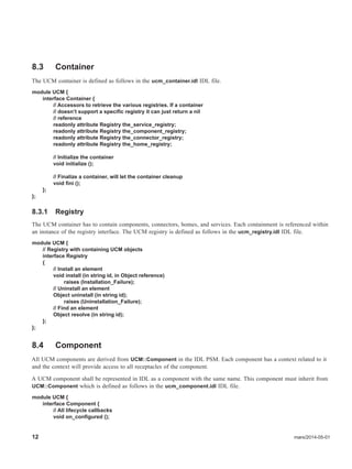
7.1.1 High Level Overview
UCM defines a unified component model in order to model, implement, and deploy components in a standardized way.
Components use ports to provide and use services to/from other entities including (but not limited to) UCM components,
other (legacy) software services, and hardware devices. Ports provide the specific connections using different interaction
patterns which at the end allow interaction with other entities. Supported interaction patterns are at least request-reply and
publish-subscribe.
Components are hosted at runtime by a UCM container. The container provides services to a “component executor” which
implements the user business logic. The container also provides a standardized API for managing components hosted by
the UCM container. Using this standardized API additional deployment models can be defined. These deployment models
can, for example, use the OMG Deployment and Configuration [DEPL] standard. In more constrained environments a
minimalistic deployment model can use this standardized API.
A port of the component is connected inside the model using a specific interaction pattern. At runtime the interaction
pattern is delivered by a connector fragment which is deployed together with the component in the container. The
connector fragment implementation handles interoperability of the port using a specific communication mechanism.
The user defined business logic is implemented in the “component executor”. The implementation uses a specific UCM
PSM. Components implemented using different PSMs interoperate when they use the same interaction pattern using the
same communication mechanism.
13. 6 mars/2014-05-01
Components can be grouped together to form an assembly. Either a component or an assembly can be deployed as one
entity by the deployment model.
7.1.2 Container
The UCM container hosts the components and connectors at runtime. The container exposes two different APIs. First it
exposes a “deployment API”. This deployment API can be used to manage the set of hosted components within the
container. This can for example be a deployment tool that interacts with the container or a monitor tool that provides
insight into the running system.
Secondly the container provides a service API to the components it hosts to access the container and additional services.
Note – Instead of deployment API we could also call it containment or management API
7.1.2.1 Component Hosting
The deployment API provides the deployment model the service to add and remove components from the container. By
standardizing this API different deployment models can be defined as additions to the UCM core. In order to be more
flexible with respect to implementation differences and future changes components are not directly registered into the
container, but through a standardized proxy that contains the reference to the component, the “locator”. This locator
allows the container access to the component, but also provides access to other entities that are related to a component.
Note – A standardized proxy approach for homes, connectors, and services would increase flexibility for the implementation
of UCM. This is something that is not the concern of the component developer.
7.1.2.2 Container Service Registry
The container service registry provides a flexible way to install services within the container. All components within one
container share the same container services. Services can be installed by the deployment model, components, and
connectors. It is the responsibility of the entity that installs a service into the container to also remove this service from
the container.
Note – Also here a locator should be registered
7.1.2.3 Execution Model
The default UCM execution model is a single threaded and non reentrant model with inversion of control. This model is
the simplest execution model, but will not work for all UCM systems. With UCM we don’t want to restrict the number of
different runtime execution models. The Messaging Container Services as described in Section 7.1.6.2 encapsulate
execution models.
7.1.3 Component
7.1.3.1 Component Context
The UCM “component context” provides the component access to the references that are tied to the component ports, as well
as the service registry.
As part of the component the ports the component uses are specified. Within the runtime environment the references for these
ports can be retrieved from the component context. The component specific context API is inherited from the generic UCM
context. The component specific context is generated based on the component definition. The content of the component
context can change during runtime of the component.
14. mars/2014-05-01 7
Discussion – In our current proposal we have a generic static context API where the name of the port is one of the arguments
of each operation which will lead to a smaller API, but within the context implementation more string matching has to happen.
Also, a change in the port definition of the component without a change to the implementation of the component will lead to a
runtime error instead of a compile error. This enables some template programming because the operation names and signatures
are constant.
7.1.3.2 Component Lifecycle
All components will go through a predefined lifecycle during their existence. Using the lifecycle callbacks the component
developer can react at specific predefined points in the existence of a component. These lifecycle callbacks are called by
the runtime environment at predefined moments. The following lifecycle callbacks are called.
• on_configured: the component has been created and all its initial configuration values have been set and the compo-
nent changes from created state to the passive state. It should now prepare for handling incoming requests. At the
moment this operation returns it has to serve these incoming requests
• on_activate: the component is allowed to make outgoing requests and changes from the passive state to the active state
• on_passivate: the component must stop making outgoing requests and but still should expect incoming requests. It
changes back to the passive state
• on_remove: the component changes from the passive state to the created state. It could now get removed, or get a dif-
ferent configuration and change back to the passive state
Note – Should there be an option for when a component is not interested in a particular lifecycle callback? The current
IDL2C++11 local language mappings require that all callbacks are implemented. Can we do something about this, maybe
some new annotation? Tag the interface or operation as listener?
Discussion – What if different domains would like different lifecycle models? Those models could be simpler, but also more
complex than the default model we propose. Would this require the lifecycle methods to be on a separate interface or would
there be a different component base? How would this affect the deployment model?
15. 8 mars/2014-05-01
7.1.3.3 Component Configuration Values
Components can define attributes using the UCM type system. The UCM runtime could support the ability to set these
defined attributes to a default for a given component. Any deployment model supporting UCM should deliver the
capability to set these defined attributes to a specific value after the creation of the component.
In order for the deployment model to set the attributes, any component defining attributes has to define a “configurator”.
This configurator implements the ability to set the value of a set of attributes of the component.
7.1.3.4 Component Facets
For each facet of a component a get_<foo> factory operation is added to the component executor (foo has to be replaced with
the concrete facet name).
7.1.3.5 Component Receptacles
For each receptacle of a component a get_<foo> operation is added to the component context (foo has to be replaced with the
concrete receptacle name).
7.1.4 Connectors
A connector ‘connects’ a component to another entity. This could be another component, but also non-component
software services, legacy systems, or hardware devices. A connector fragment implements the functionality to translate a
specific port to a specific communication middleware (CORBA, DDS, shared memory, etc), other non-component
services, or hardware devices.
This doesn’t necessarily imply that there is a one to one connection between the entities a connector connects. At
deployment time the logical connector is split into “connector fragments” which are deployed collocated with the entities
they ‘connect’. Connector fragments include support for attributes using the UCM type system. Connector fragments are
intended to be small and lightweight and are deployed into the container.
7.1.5 Homes
UCM supports the concept of a home. A home is a component factory which provides the ability to create components at
runtime. Homes can be deployed using the UCM deployment API. On a home attributes can be defined, just as with
components. These attributes can be set by a deployment model.
The user has to provide an implementation of the home in the “home executor”. In addition to attribute accessors, a home
executor has a create() operation. The responsibility of this create operation is to return a new created component
executor. The UCM generated code for a home will create the needed component locator for the created component
executor. After that the UCM infrastructure will install the component into the same container as the home. It is the
responsibility of the user of the home to then set all attributes on the created component and walk the component through
its lifecycle states.
Note – Another solution would be that the home executor (or generated code) would also automatically walk the component
through its lifecycle states, but that would prevent any more complex usage of homes where the user for example wants to
deploy multiple components/connectors and then have this set of components walk through their lifecycle per a consistent
state transition sequence. To keep the UCM model for a home simple, setting of attribute configuration values onto the new
component is the responsibility of the entity using the home.
Note – Adding user defined create operations with custom arguments only complicates UCM and doesn’t bring any additional
value to our idea. These custom operations can’t be used by any generic deployment model, and they define two ways of con-
16. mars/2014-05-01 9
struction (through a home and without a home) with different behaviour and semantics. If the constructed component has to
get some initial settings, the configuration values of the component are the way to do this. This approach works with and with-
out homes. It could be an option to pass the configuration values of the component to the create() operation of the home. The
home is then able to make some create decisions based on the passed configuration values. It would simplify the model when
regular component instantiation and home support are using the same concepts.
7.1.6 Container services
Container services offer a way to extend the functionality of a container without an explosion of the container API and
built-in functionality for the container itself. Container services are deployed and installed into a container, to be used by
any component or connector within that container.
7.1.6.1 Timer Container Service
It is a common use case that components need to react to single or recurring timers. By defining a standard timer container
service component developers can schedule, cancel, and react to timers in a standardized way. The timer container service will
provide the service to schedule, cancel, and react to a timer.
7.1.6.2 Messaging Container Service
UCM doesn’t have a mandatory dependency on any communication middleware. This implies that UCM cannot use for
example RTCORBA for its execution models. Also, a different kind of communication middleware can deliver different
threading semantics which UCM has to shield the components against. For example, several DDS implementations are multi-
threaded by design. Multiple DDS threads could callback into user code at the same moment which would violate the default
single threaded UCM model.
The messaging container services deliver the infrastructure for the various UCM execution models. They comprise the queue
and the dispatcher service. The queue service provides the support to retrieve a message queue and schedule, cancel, and
retrieve messaging objects into and from a message queue. The dispatcher service uses the queue service for retrieving
messaging objects which it invokes as operations on the components.
By defining multiple types of queue and dispatcher implementations different execution models can be achieved, like single
threaded (one queue with a single-threaded dispatcher), multi-threaded (one queue with a multi-threaded dispatcher), single
threaded per component (one queue per component and a single threaded dispatcher for each component), etc, as well as
allowing for different prioritization models (FIFO, LIFO, etc).
In order for the execution models to work, any connector or other service which wants to invoke operations on a user
component has to use the messaging container service. A violation of this rule will break the execution model semantics. The
messaging container service is not something user components will interact with explicitly. It is purely for connectors and
other container services.
7.1.7 Assemblies
An assembly is a grouping of components with internal connections defined between these components. The assembly concept
makes it easier to reuse a group of components, as well as to define complex systems using nested hierarchies of assemblies.
The user of an assembly only has to connect the external visible ports of the assembly, not all the internal ports.
A definition of an assembly results in a factory and locator for that assembly. The deployment model is able to deploy the
assembly with one factory invocation. It is the responsibility of the assembly factory to create all internal components and
connectors, connect all internal ports, and redirect configuration values to the appropriate internal entities. The deployment
model can then connect the external ports of the assembly.
Note – Allowing the creation of an assembly factory greatly simplifies deployment of larger systems
17. 10 mars/2014-05-01
7.2 Interaction patterns
7.2.1 Request/reply
UCM supports the request/reply interaction pattern. This interaction pattern is provided as a function style API, defined
as a set of user-defined operations. The component developer can invoke an operation at the programming language level
with the ability to send and receive user data.
UCM will allow the user to group operations into an interface. This single user-defined interface is grouped together with
additional interfaces defined by the UCM request/reply port itself, as needed, to support alternative interaction semantics
such as asynchronous client side invocation or asynchronous server side implementation. The collective set of interfaces
for a single UCM request/reply port are available to the component executor.
Note – A UCM port is similar to the LwCCM extended port.
For asynchronous client side invocations UCM will use the concepts of the existing AMI4CCM standard [AMI4CCM].
The UCM request/reply port containing the user defined interface is extended with the AMI4CCM implied interfaces.
For asynchronous server side functionality UCM will use the concepts of the Asynchronous Message Handling (AMH) as
available as part of TAO [AMH]. AMH defines a set of interface conversion rules that lead to a set of interfaces on the
server side. The UCM request/reply port containing the user defined interface is extended with the AMH implied
interfaces.
By standardizing the request/reply interaction pattern different UCM implementations can support different kinds of
communication middleware solutions. In order to guarantee interoperability a mapping of the request/reply interaction
pattern to a specific communication middleware has to be standards based at the wire protocol level.
Note – These mappings shall not be part of the core UCM specification but will be included in separate specifications. In order
to simplify the discussion some mapping details are part of this initial submission.
7.2.1.1 CORBA Based Request/Reply
UCM can be implemented with CORBA based request/reply interaction support. A CORBA request/reply specification
will standardize the way UCM ports, interfaces, and type system are translated to CORBA interfaces and types.
The main difference between CORBA and UCM is the definition of the interface. With UCM an interface is local by
default, whereas with CORBA an interface is remote by default. A CORBA based request/reply interaction style can be
easily defined so that the interfaces of the ports connected to the CORBA based request/reply connectors are also
available in a remote version.
Just as with DDS, CORBA defines a set of policies to control its behavior. The CORBA based request/reply part of UCM
will also standardize the way CORBA policies can be configured on the CORBA connector fragments.
A CORBA request/reply connection in the model is deployed as two collocated CORBA connector fragments. The server
side of a CORBA connector will have configuration values indicating how the CORBA connector fragment has to register
itself to the CORBA middleware. The client side of a CORBA connector will have configuration values that will enable
it to connect to the correct CORBA servant. It is up to the CORBA connector fragments to establish the connection, as
specified by connector configuration values. This could for example enforce that the connection is created at startup or
that it is delayed to the moment the connection gets used the first time.
18. mars/2014-05-01 11
7.2.1.2 DDS Based Request/Reply
UCM can be implemented with DDS based request/reply interaction support. With a function based API the DDS request/
reply interaction support has to standardize the mapping of a port and each of its operations to DDS topics. The identity of the
port at runtime has to be standardized so that connections made as part of the deployment are handled correctly at runtime. The
proposal is to use part of the work of the RPC over DDS efforts [RPCDDS]. Because a revised RPCDDS submission is in
progress this part is left further unspecified until the RPC over DDS standard is in place.
7.2.2 Publish/Subscribe
UCM supports the publish/subscribe interaction pattern. The UCM core specification will at least standardize an event
and state based interaction pattern.
7.2.2.1 DDS Based Publish/Subscribe
Note – The event and state interaction patterns can be defined by reusing the DDS4CCM specification [DDS4CCM].
7.2.2.2 CORBA Event Based Publish/Subscribe
Note – There could be an addon specification that defines the publish/subscribe event interaction pattern using the CORBA
event channel.
7.3 D&C Based Deployment Model
The OMG has an existing Deployment and Configuration [DEPL] standard for deployment. UCM based systems can be
deployed with D&C but this is slightly different compared to, for example, a deployment of a LwCCM system. In the
deployment plan for a UCM based system only connections between the collocated components and connector fragments are
defined. The CORBA connections as part of a LwCCM plan are replaced by CORBA connectors that are collocated with the
components. The CORBA connector fragments are configured using configuration values with the needed meta data the
fragment needs to provide or use a CORBA connection. It is the responsibility of the CORBA connector fragment to setup the
CORBA connection. This will not be done by the D&C toolchain. This is similar to the DDS4CCM connector fragments
which are configured using configuration values for the topic, domain, and other DDS configuration settings. It is up to DDS
itself, within a DDS4CCM connector fragment implementation to connect publishers and subscribers together.
Each connector fragment has the responsibility to setup the connection that is needed. With DDS this establishment is left to
the underlying middleware, with CORBA it has to be handled explicitly in the connector.
7.3.1 Other Deployment Models
Since UCM standardizes the deployment container API, other deployment models are possible. A different deployment model
could for example define much smaller and easier to use deployment plans. Additional deployment models could focus on
single node deployment capabilities which lead to much more flexibility than the D&C based deployment models.
7.4 Various Comments and Ideas
The COPI part of QoS4CCM is dependent on the CORBA built in support of CCM. We shouldn’t try to support that.
What about the QoS Enablers part of QoS4CCM? We can see some use cases for that.
20. mars/2014-05-01 11
8 IDL Platform Specific Model
This chapter describes the IDL PSM for UCM. The IDL within this chapter can be translated to a specific programming
language using the already existing standardized IDL Language Mappings.
As reference for the IDL specification this submission refers to IDL4 [IDL4]. From IDL4 the UCM IDL PSM uses the
following building blocks:
• Core Data Types
• Interfaces - Basic
• Components - Basic
• Components CCM - Specific
• Extended Ports and Connectors
• Template Modules
• Extended Data-Types
• Annotations
8.1 Introduction
In the context of UCM all IDL interfaces are local interfaces.
8.1.1 Differences With LwCCM
The UCM IDL PSM is similar in some areas to LwCCM but there are several key differences:
• Interfaces are implied local
• No usage of the IDL keyword ‘supports’ and its implied CORBA dependency
• Component and home attributes are local
• No mandatory dependency on CORBA
• No ability to retrieve the CORBA side of a component through the component context
• Interfaces derive directly or indirectly from UCM::Object instead of CORBA::Object
• No usage of valuetypes
• Reduced functionality for homes
8.2 Core
The UCM core IDL types are all defined in the ucm.idl IDL file.
21. 12 mars/2014-05-01
8.3 Container
The UCM container is defined as follows in the ucm_container.idl IDL file.
module UCM {
interface Container {
// Accessors to retrieve the various registries. If a container
// doesn’t support a specific registry it can just return a nil
// reference
readonly attribute Registry the_service_registry;
readonly attribute Registry the_component_registry;
readonly attribute Registry the_connector_registry;
readonly attribute Registry the_home_registry;
// Initialize the container
void initialize ();
// Finalize a container, will let the container cleanup
void fini ();
};
};
8.3.1 Registry
The UCM container has to contain components, connectors, homes, and services. Each containment is referenced within
an instance of the registry interface. The UCM registry is defined as follows in the ucm_registry.idl IDL file.
module UCM {
// Registry with containing UCM objects
interface Registry
{
// Install an element
void install (in string id, in Object reference)
raises (Installation_Failure);
// Uninstall an element
Object uninstall (in string id);
raises (Uninstallation_Failure);
// Find an element
Object resolve (in string id);
};
};
8.4 Component
All UCM components are derived from UCM::Component in the IDL PSM. Each component has a context related to it
and the context will provide access to all receptacles of the component.
A UCM component shall be represented in IDL as a component with the same name. This component must inherit from
UCM::Component which is defined as follows in the ucm_component.idl IDL file.
module UCM {
interface Component {
// All lifecycle callbacks
void on_configured ();
22. mars/2014-05-01 13
void on_activate ();
void on_passivate ();
void on_remove ();
// Operation to set the component context onto the component
void set_context (in Context context);
};
};
8.4.1 Port
All UCM component ports are defined per IDL GIS templated module, connector and extended port concepts using the
IDL "port" keyword. No additional IDL syntax extensions or changes are required. An extended "port" is defined by
selecting the name of the port defining the desired interaction pattern from within an IDL templated module instantiation
of the desired interaction pattern.
8.4.2 Locator
A locator will be registered with a container for each component. It provides access to the component, context, and
configurator. The locator is defined as follows in the ucm_locator.idl IDL file.
module UCM {
// An instance of the Locator is registered with the container so that the infrastructure has a
// standardized way to find the component, context, and configurator
interface Locator {
readonly attribute Component the_component;
readonly attribute Context the_context;
readonly attribute Configurator the_configurator;
};
8.4.3 Configurator
For each component a configurator is generated which provides the functionality to use a set of configuration values and
set them onto the component executor. At the moment a component doesn’t have any configuration values it can use a nil
reference for the configurator. The configurator is defined as follows in the ucm_configurator.idl IDL file.
module UCM {
// Make sure the concrete type of the value is a typedef
typedef Any ConfigValueType;
struct ConfigValue {
string name;
ConfigValueType value;
};
typedef sequence<ConfigValue> ConfigValues;
typedef sequence<string> NameList;
exception ConfigurationError {
// List of attribute names which we were unable to set
NameList name_list;
};
interface Configurator {
// Set the configuration on the component. Tries to set all values onto the component and in case some
// fail, gathers the names of the ones that did fail and raises them. In case there are then multiple attributes
// incorrect they are all listed preventing a trial/error to just fix one each time
void set_configuration (in Object object, in ConfigValues descr)
23. 14 mars/2014-05-01
raises (ConfigurationError);
};
};
8.4.4 Context
The generic part of the UCM Context is defined as follows in the ucm_context.idl in the IDL file.
module UCM {
typedef sequence<Object> ObjectSeq;
interface Context {
readonly attribute Registry the_service_registry;
void connect (in FeatureName name , in Object connection, in string conn_name)
raises (InvalidName, InvalidConnection, AlreadyConnected);
Object disconnect (in FeatureName name, in string conn_name)
raises (InvalidName, InvalidConnection, NoConnection);
ObjectSeq get_receptacle (in FeatureName receptacle_name);
};
For each component a specific component context is generated in the same module as the component. This context
derives from UCM::Context and for each receptacle of the component a separate operation is added.
module Foo {
interface FooContext : Context {
Object get_... ()
};
};
8.5 Home
A UCM Home is defined using the IDL home syntax. For example a home for a component Foo is defined as follows.
module MyModule {
home FooHome manages Foo {
};
// Implied IDL
interface FooHomeExecutor {
Foo create ()
};
};
The home can contain attributes which can be set by a deployment tool. A home has the ability to define and use
attributes.
8.6 Container services
With the minimalistic container the way to extend its functionality is to provide container services. The UCM standard
defines some optional container services which could be delivered by a UCM implementation.
24. mars/2014-05-01 15
8.6.1 Timer Container Service
The timer container service provides the ability to schedule, cancel, and react to time based triggers. The timer service is
defined as follows in the ucm_timer_service.idl IDL file.
module UCM {
struct TimeT {
long seconds;
unsigned long nanosec;
};
enum timeout_enum_t {
ABSOLUTE_TIME,
RELATIVE_TIME
};
// Timeout can be relative or absolute, as denoted by the flag.
struct timeout_t {
// Time value for timeout
TimeT time_val;
// Timeout type
timeout_enum_t flag;
};
interface Timer_Callback {
void on_timeout (in timeout_t time);
};
interface Timer {
void cancel ();
boolean is_canceled ();
};
interface Timer_Service {
Timer start_scheduler_periodic (
in timeout_t delay_time,
in timeout_t rate,
in Timer_Callback cb,
in Context ctx);
Timer start_scheduler_sporadic (
in timeout_t time,
in Timer_Callback cb,
in Context ctx);
};
};
8.6.2 Messaging Container Services
The messaging component container services provide a flexible queuing and dispatching system.
Note – Before defining the concrete IDL for this service we first want to assess the input from the other UCM interested par-
ties for their interest in such a service.
8.6.2.1 Queue Service
TBD
25. 16 mars/2014-05-01
8.6.2.2 Dispatcher Service
TBD
8.7 Example Component
Below is a notional user level IDL example definition of a UCM component. A number of assumptions have been made
per this example, as delineated below. Most of these assumptions relate to UCM compliant generic request-reply (per
AMI4CCM and DDS4CCM precedent) and pub-sub (per DDS4CCM precedent) interaction pattern connector
specifications, which must be defined specifically for UCM in order to ensure that they are middleware agnostic.
1) Suggested normative names for standard UCM #include files and connector types (DDS and CORBA assumed
initially).
2) Connector namespace and templated module names for compliant UCM connectors.
3) Notional syntax for instantiating a request-reply templated module to define a UCM request-reply connector type. This
is subject to further review against AMI4CCM concepts, since something similar in concept with an IDL interface defined
as a template parameter was initially rejected during the DDS4CCM spec development cycle.
4) Continued need for a user-defined sequence typedef for pub-sub messages, per the DDS4CCM specification.
5) Assume UCM only uses the IDL "port" keyword to define user-level component ports. Basic implicitly local
"provides" and "uses" ports are to be used only within an IDL extended "porttype" definition, which are then used to
define an IDL "mirrorport" on a UCM connector type, per the IDL specification.
6) Assume the basic DDS4CCM ConnectorStatusListener port is rolled into the fully encapsulated UCM pub-sub State
and Event connectors, so that it will no longer have to be specified at the user component level as a basic "provides" port
per the prior assumption. As such, it would only show up in a deployment model connection list, rather than as a user-
defined component port artifact.
7) Assume existing DDS4CCM pub-sub connector types are made more generic for UCM, to get rid of DDS specifics like
dds_entity ports and DDS prefixes on types and port names.
8) Assume rename of DDS4CCM pub-sub connector extended porttypes for UCM to remove "DDS_" prefixes, changed
to "Write", "Update", "Listen", "StateListen", "Get", and "Read". Per these names, we also assume no State vs. Event
connector rename of their shared Listen, Read and Get porttypes to remove ambiguity in IDL definitions, which would
offer a compile time optimization if renamed to be unique for each.
9) Assumes UCM extended request-reply connectors offer four separate client and server side, synchronous and
asynchronous extended porttypes to satisfy the required UCM interaction semantics, called "Provides", "ProvidesAsync",
"Uses" and "UsesAsync".
// Notional user level IDL PSM definition example for a UCM component
#include <ucm.idl> // UCM Core types
#include <ucm_request_reply.idl> // UCM request/reply interaction pattern definition
#include <ucm_pub_sub_event.idl> // UCM pub/sub event interaction pattern definition
#include <ucm_pub_sub_state.idl> // UCM pub/sub state interaction pattern definition
module Example {
typedef string StatusString;
// Define a "Control Service" interface
interface ControlService {
26. mars/2014-05-01 17
boolean setValue(in double dVal);
void start();
void stop();
};
// Define a "Status Service" interface
interface StatusService {
void getStatus(out StatusString status);
};
// Define a "Data Main" message type
struct DataMainMsg {
long mainValue; //@Key
short otherValue;
};
// Define a "Data Aux" message type
struct DataAuxMsg {
long auxValue;
boolean isGood;
};
// Define/instantiate a "Control Service" request/reply module
module UCM::RequestReply<ControlService> myControlService;
// Define/instantiate a "Status Service" request/reply module
module UCM::RequestReply<StatusService> myStatusService;
// Define/instantiate a "Data Main" pub/sub state module
typedef sequence <DataMainMsg> DataMainMsgSeq;
module UCM::PubSubState <DataMainMsg, DataMainMsgSeq> myDataMain;
// Define/instantiate a "Data Aux" pub/sub event module
typedef sequence <DataAuxMsg> DataAuxMsgSeq;
module UCM::PubSubEvent <DataAuxMsg, DataAuxMsgSeq> myDataAux;
// Define our example UCM component with 4 UCM (extended GIS) ports
component myUcm_comp {
port myControlService::Provides controlSvc; // sync service port example
port myStatusService::UsesAsync status; // async client port example
port myDataMain::StateListen dataMainSub; // state subscriber port example
port myDataAux::Write dataAuxPub; // event publisher port example
};
};